

Half-Bridge LLC Resonant Converter Design Using FSFR-Series ...
Half-Bridge LLC Resonant Converter Design Using FSFR-Series ...
Half-Bridge LLC Resonant Converter Design Using FSFR-Series ...

Create successful ePaper yourself
Turn your PDF publications into a flip-book with our unique Google optimized e-Paper software.
AN-4151 APPLICATION NOTE<br />
RMS <br />
ID I<br />
(27)<br />
o<br />
4<br />
Meanwhile, the ripple current flowing through output<br />
capacitor is given as:<br />
2<br />
RMS Io2 2 8<br />
Co ( ) o o<br />
I I I<br />
(28)<br />
2 2<br />
8<br />
The voltage ripple of the output capacitor is:<br />
<br />
Vo Io R<br />
(29)<br />
C<br />
2<br />
where RC is the effective series resistance (ESR) of the<br />
output capacitor and the power dissipation is the output<br />
capacitor is:<br />
P . ( I ) R<br />
(30)<br />
RMS 2<br />
Loss Co Co C<br />
(<strong>Design</strong> Example) The voltage stress and current<br />
stress of the rectifier diode are:<br />
VD 2( Vo VF) 2(240.9) 49.8<br />
RMS <br />
ID Io 6.28A<br />
4<br />
The 100V/20A Schottky diode is selected for the<br />
rectifier considering the voltage overshoot caused by<br />
the stray inductance.<br />
The RMS current of the output capacitor is:<br />
2<br />
RMS Io2 2 8<br />
ICo ( ) Io Io 3.857A<br />
2 2<br />
8<br />
When two electrolytic capacitors with ESR of 80mΩ<br />
are used in parallel, the output voltage ripple is given<br />
as:<br />
0.08<br />
Vo IoRC 8 ( ) 0.50V<br />
2 2 2<br />
The loss in electrolytic capacitors is:<br />
RMS 2 2<br />
PLoss. Co ( ICo) RC3.857 0.04 0.60W<br />
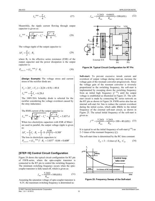
[STEP-10] Control Circuit Configuration<br />
Figure 24 shows the typical circuit configuration for RT pin<br />
of <strong>FSFR</strong>-series, where the opto-coupler transistor is<br />
connected to the RT pin to control the switching frequency.<br />
The minimum switching frequency occurs when the optocoupler<br />
transistor is fully tuned off, which is given as:<br />
5.2k<br />
fmin 100( kHz)<br />
(31)<br />
Rmin<br />
Assuming the saturation voltage of opto-coupler transistor is<br />
0.2V, the maximum switching frequency is determined as:<br />
5.2k4.68k fmax ( ) 100( kHz)<br />
(32)<br />
R R<br />
min max<br />
Control<br />
IC<br />
© 2007 Fairchild Semiconductor Corporation www.fairchildsemi.com<br />
Rev. 1.0.1 • 5/15/12 12<br />
R max<br />
R min<br />
External S/S<br />
R SS<br />
C SS<br />
RT<br />
LVcc<br />
VDL<br />
SG PG<br />
Figure 24. Typical Circuit Configuration for RT Pin<br />
Soft-start: To prevent excessive inrush current and<br />
overshoot of output voltage during start-up, increase the<br />
voltage gain of the resonant converter progressively. Since<br />
the voltage gain of the resonant converter is reversely<br />
proportional to the switching frequency, the soft-start is<br />
implemented by sweeping down the switching frequency<br />
from an initial high frequency (f ISS ) until the output<br />
voltage is established as illustrated in Figure 25. The softstart<br />
circuit is made by connecting RC series network on<br />
the RT pin as shown in Figure 24. <strong>FSFR</strong>-series also has an<br />
internal soft-start for 3ms to reduce the current overshoot<br />
during the initial cycles, which adds 40kHz to the initial<br />
frequency of the external soft-start circuit, as shown in<br />
Figure 25. The actual initial frequency of the soft-start is<br />
given as:<br />
ISS 5.2k5.2k f ( ) 100 40 ( kHz)<br />
(33)<br />
R R<br />
min<br />
It is typical to set the initial frequency of soft-start (f ISS ) as<br />
2~3 times of the resonant frequency (fo).<br />
The soft-start time is determined by the RC time constant:<br />
T 3~4timesof<br />
R C (34)<br />
f ISS<br />
f s<br />
3ms<br />
40kHz<br />
SS<br />
SS SS SS<br />
3~4 times of RC time constant<br />
Control loop<br />
take over<br />
Figure 25. Frequency Sweep of the Soft-start<br />
time


