Photovoltaics in Buildings A Design Guide - DTI Home Page
Photovoltaics in Buildings A Design Guide - DTI Home Page
Photovoltaics in Buildings A Design Guide - DTI Home Page

Create successful ePaper yourself
Turn your PDF publications into a flip-book with our unique Google optimized e-Paper software.
6<br />
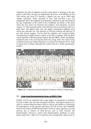
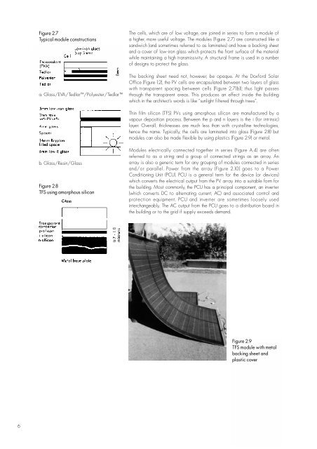
Figure 2.7<br />
Typical module constructions<br />
a. Glass/EVA/Tedlar/Polyester/Tedlar<br />
b. Glass/Res<strong>in</strong>/Glass<br />
Figure 2.8<br />
TFS us<strong>in</strong>g amorphous silicon<br />
The cells, which are of low voltage, are jo<strong>in</strong>ed <strong>in</strong> series to form a module of<br />
a higher, more useful voltage. The modules (Figure 2.7) are constructed like a<br />
sandwich (and sometimes referred to as lam<strong>in</strong>ates) and have a back<strong>in</strong>g sheet<br />
and a cover of low-iron glass which protects the front surface of the material<br />
while ma<strong>in</strong>ta<strong>in</strong><strong>in</strong>g a high transmissivity. A structural frame is used <strong>in</strong> a number<br />
of designs to protect the glass.<br />
The back<strong>in</strong>g sheet need not, however, be opaque. At the Doxford Solar<br />
Office (Figure 1.2), the PV cells are encapsulated between two layers of glass<br />
with transparent spac<strong>in</strong>g between cells (Figure 2.7(b)); thus light passes<br />
through the transparent areas. This produces an effect <strong>in</strong>side the build<strong>in</strong>g<br />
which <strong>in</strong> the architect’s words is like “sunlight filtered through trees”.<br />
Th<strong>in</strong> film silicon (TFS) PVs us<strong>in</strong>g amorphous silicon are manufactured by a<br />
vapour deposition process. Between the p and n layers is the i (for <strong>in</strong>tr<strong>in</strong>sic)<br />
layer. Overall, thicknesses are much less than with crystall<strong>in</strong>e technologies,<br />
hence the name. Typically, the cells are lam<strong>in</strong>ated <strong>in</strong>to glass (Figure 2.8) but<br />
modules can also be made flexible by us<strong>in</strong>g plastics (Figure 2.9) or metal.<br />
Modules electrically connected together <strong>in</strong> series (Figure A.4) are often<br />
referred to as a str<strong>in</strong>g and a group of connected str<strong>in</strong>gs as an array. An<br />
array is also a generic term for any group<strong>in</strong>g of modules connected <strong>in</strong> series<br />
and/or parallel. Power from the array (Figure 2.10) goes to a Power<br />
Condition<strong>in</strong>g Unit (PCU). PCU is a general term for the device (or devices)<br />
which converts the electrical output from the PV array <strong>in</strong>to a suitable form for<br />
the build<strong>in</strong>g. Most commonly, the PCU has a pr<strong>in</strong>cipal component, an <strong>in</strong>verter<br />
(which converts DC to alternat<strong>in</strong>g current, AC) and associated control and<br />
protection equipment. PCU and <strong>in</strong>verter are sometimes loosely used<br />
<strong>in</strong>terchangeably. The AC output from the PCU goes to a distribution board <strong>in</strong><br />
the build<strong>in</strong>g or to the grid if supply exceeds demand.<br />
Figure 2.9<br />
TFS module with metal<br />
back<strong>in</strong>g sheet and<br />
plastic cover