Finite Element Analysis of X-Ray Targets
Finite Element Analysis of X-Ray Targets
Finite Element Analysis of X-Ray Targets

Create successful ePaper yourself
Turn your PDF publications into a flip-book with our unique Google optimized e-Paper software.
A. Plankensteiner, P. Rödhammer RM 2 9<br />
Summary<br />
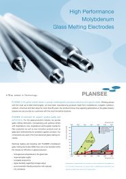
<strong>Finite</strong> <strong>Element</strong> <strong>Analysis</strong> <strong>of</strong> X-<strong>Ray</strong> <strong>Targets</strong><br />
Arno Plankensteiner, Peter Rödhammer<br />
Technology Center, Plansee AG, Reutte, Austria<br />
Over the last decades the demand for higher X-ray doses in novel diagnostic<br />
procedures based on medical computer tomography has led to larger and more<br />
complex designs <strong>of</strong> X-ray targets. In the present work the limits to up-scaling <strong>of</strong><br />
present-day designs using the present standard materials are analyzed using <strong>Finite</strong><br />
<strong>Element</strong> <strong>Analysis</strong> (FEA). The commercial FEM package ABAQUS/Standard V6.5 was<br />
employed. Simulations were based on an axi-symmetric model and an elastic-plastic<br />
material law for the metallic components. X-ray targets with diameter 190mm (T190)<br />
and 250mm (T250) operated at 150Hz and 250Hz were analyzed. Exposures <strong>of</strong><br />
100kW/10sec and 100kW/30sec were chosen to represent potential future<br />
requirements.<br />
According to the results <strong>of</strong> the present FEA the scale-up <strong>of</strong> present designs <strong>of</strong> X-ray<br />
targets using TZM as base material may be expected to reach its limits at diameters <strong>of</strong><br />
~ 250mm and at ratings equivalent to 100kW/10sec exposures. It is concluded that<br />
novel materials with mechanical properties improved markedly beyond those <strong>of</strong> TZM,<br />
combined with novel designs, are prerequisite for the rateability <strong>of</strong> X-ray targets<br />
beyond this threshold.<br />
Keywords<br />
Computer tomography, X-ray anode, finite element analysis, high temperature<br />
plasticity, molybdenum alloy, tungsten rhenium alloy, graphite
10 RM 2 A. Plankensteiner, P. Rödhammer<br />
1. Introduction<br />
Over the last three decades the demand for higher X-ray doses in novel diagnostic<br />
procedures based on medical computer tomography has led to ever larger and more<br />
complex designs <strong>of</strong> rotating X-ray targets. At present, anodes consisting <strong>of</strong> a<br />
molybdenum alloy disc with a thin tungsten/rhenium layer serving as focal track and a<br />
graphite ring brazed to its back are the state <strong>of</strong> the art in tubes for computer<br />
tomography (CT) applications. The diameters <strong>of</strong> such anodes have increased to about<br />
200mm, and their weight to more than 5kg. At the same time, the loads experienced in<br />
application have increased dramatically. This applies to the combination <strong>of</strong> rotational<br />
frequency, power density <strong>of</strong> the electron beam generating the X-ray, input <strong>of</strong> electric<br />
energy, and the associated increase in operating temperatures. At this point in time,<br />
the materials used for X-ray targets and technologies employed for their manufacturing<br />
are becoming the limiting factors in satisfying the progressing needs <strong>of</strong> medical<br />
diagnostics. In an increasing number <strong>of</strong> applications the increasing loads lead to<br />
accelerated ageing <strong>of</strong> the W/Re focal track, to irreversible deformation or even to<br />
failure <strong>of</strong> the metal disc and/or to debonding <strong>of</strong> the joining between metal and graphite.<br />
In order to prevent these failures and to increase the envelope for operating<br />
parameters there is an urgent need for improved designs, materials, and joining<br />
technologies.<br />
The present work is motivated by recurring reports from the field that anodes used in<br />
advanced diagnostic techniques had failed. Post-mortem analysis showed that the<br />
anodes had deformed and acquired an unbalance, and that in consequence the<br />
brazing had failed between the metal cap and the graphite back.<br />
In this paper results <strong>of</strong> a finite element analysis for X-ray anodes are presented aiming<br />
at evaluating present and up-scaled anode designs with regard to foreseeable future<br />
anode ratings. One aim <strong>of</strong> this analysis is to gauge the need for improvement <strong>of</strong> the<br />
tensile properties <strong>of</strong> up-graded or novel molybdenum alloys required for present and<br />
future diagnostic techniques in CT tomography. An axisymmetric model is adopted<br />
throughout the calculations. The stresses in the compound metal-graphite anodes<br />
resulting from the production history are simulated. Deformations as well as<br />
temperature and stress/strain distributions resulting from present and anticipated future<br />
loading conditions in tube applications are calculated.
A. Plankensteiner, P. Rödhammer RM 2 11<br />
2. Operational requirements for CT applications<br />
Basic requirements for X-ray anodes are highly stable radiation output and high<br />
voltage stability over the lifetime <strong>of</strong> the tube (~10 5 exposures). Form stability <strong>of</strong> the<br />
focal track and balance retention are prerequisite for image quality and bearing life,<br />
respectively. Demanding procedures such as a CT spiral scan call for cyclic inputs <strong>of</strong><br />
electric energy <strong>of</strong> up to 60kW/30sec with cooling times up to 10 minutes. Rotational<br />
frequencies for anodes with a diameter <strong>of</strong> 200mm are presently constrained to <<br />
150Hz due to limitations in the material properties. Temperatures at the brazing<br />
interface are designed to stay below 1400°C, with a safety margin up to 1600°C in<br />
case <strong>of</strong> disruptions. Novel diagnostic techniques will involve considerably higher<br />
ratings. In particular, the size <strong>of</strong> the focal spot will be reduced to < 1 x 10mm 2 , at power<br />
levels < 100kW and energy inputs < 1MJ.<br />
One answer to inadequate life <strong>of</strong> the focal track at present ratings, and much more so<br />
at novel techniques, lies in anodes with larger diameters rotating at higher rotational<br />
speeds. Here, an up scaling to diameters <strong>of</strong> 250mm and an increase <strong>of</strong> the rotational<br />
frequency up to 200Hz appear feasible based on an evolution <strong>of</strong> present-day tube<br />
technology. However, the resulting centrifugal forces will put still higher demands on<br />
the mechanical properties <strong>of</strong> the materials used in the design <strong>of</strong> the X-ray targets. This<br />
holds true in particular for the molybdenum alloy disc that is largely responsible for the<br />
form stability <strong>of</strong> the compound anode.<br />
3. Design and production aspects <strong>of</strong> X-ray anodes for CT<br />
applications<br />
The structural backbone <strong>of</strong> the anode is generally formed by a disk made <strong>of</strong> a<br />
dispersion strengthened molybdenum alloy such as TZM (Mo 0.5Ti 0.08Zr 0.025C),<br />
MHC (Mo 1Hf 0.1C) or closely related alloys [1]. A thin layer <strong>of</strong> a W/Re alloy (for CT<br />
applications usually W10Re) serves to generate X-rays upon impact <strong>of</strong> energetic<br />
electrons emitted from the cathode. A graphite ring is brazed to the back side <strong>of</strong> the<br />
molybdenum disc, serving both for heat storage and for heat dissipation by radiation.
12 RM 2 A. Plankensteiner, P. Rödhammer<br />
Ø190<br />
Fig. 1: CAD-half models representing different designs <strong>of</strong> X-ray targets: Ø190 with<br />
Ø190mm (left) and Ø250 with Ø250mm (right).<br />
Target Ø190 represents a typical design <strong>of</strong> metal-graphite compound X-ray anodes<br />
used in one <strong>of</strong> the highest-rating diagnostic techniques (spiral scan computer<br />
tomography) and target Ø250 represents a draft design for anticipated future<br />
applications arrived at by straightforward up-scaling <strong>of</strong> target Ø190 to larger diameter<br />
and thickness.<br />
Ø250<br />
The metal part is usually produced by means <strong>of</strong> powder metallurgical processes in the<br />
following sequence <strong>of</strong> steps:<br />
• Co-compacting the TZM and W/Re powders to a compound disk<br />
• Sintering<br />
• Hot forging to conical shape (overall degree <strong>of</strong> deformation is 25% to 40%)<br />
• Machining <strong>of</strong> metal cap<br />
• High temperature brazing <strong>of</strong> metal cap to graphite ring with brazing<br />
temperatures <strong>of</strong> ~1750°C for Ti braze or ~2000°C for V/Ta/Zr braze<br />
• Attachment <strong>of</strong> a TZM shaft (see Fig. 1) by brazing (usually Ti-braze)<br />
High temperature brazing is required in present high-end applications because<br />
operating temperatures in the brazing interface metal-graphite may exceed 1400°C.
A. Plankensteiner, P. Rödhammer RM 2 13<br />
4. Properties <strong>of</strong> materials used for X-ray anodes<br />
For TZM thermo-physical and mechanical material data have been obtained on<br />
specimens taken from anodes in the final state <strong>of</strong> production cycle, i.e. after high<br />
temperature brazing. Comparison with data for standard TZM [2] shows that the tensile<br />
properties <strong>of</strong> TZM are degraded in the course <strong>of</strong> the exposure to 2000°C during high<br />
temperature brazing. The tensile data <strong>of</strong> W/Re were evaluated on a sample specially<br />
prepared for this test under conditions comparable to those reigning during<br />
manufacture <strong>of</strong> X-ray anodes. Generally, temperature-dependent material data are<br />
used throughout the FEM analysis. In particular, temperature dependent stress-strain<br />
relationships covering the full plastic range are used for TZM and W/Re. Note that<br />
W/Re as it is present in X-ray anodes exhibits no plastic deformation below<br />
temperatures <strong>of</strong> 1000°C. Therefore, a purely elastic behaviour is assumed for W/Re at<br />
T < 1000°C.<br />
Emissivity<br />
[-]<br />
Thermal<br />
Conductivity<br />
[W/(m · K)]<br />
Specific Heat<br />
[J/(kg · K)]<br />
RT RT 1400°C RT 1400°C<br />
Graphite 0.88 135 58 706 2020<br />
TZM 0.22 123 89 226 356<br />
W10Re 0.30 77 69 132 154<br />
Table 1: Thermo-physical surface and material properties <strong>of</strong> anode grade TZM,<br />
W10Re and graphite.<br />
Density<br />
[g/cm 3 ]<br />
Young’s Modulus<br />
[GPa]<br />
Coefficient <strong>of</strong><br />
Thermal Expansion<br />
[·10 -6 /K]<br />
RT RT 1400°C RT 1400°C<br />
Graphite 1.82 12 12 4.4 6.1<br />
TZM 10.15 265 187 5.4 6.1<br />
W10Re 19.00 377 229 4.8 5.2<br />
Table 2: Mechanical material properties <strong>of</strong> anode grade TZM, W10Re and graphite.<br />
The graphite grade is IG610 from Toyo Tanso [3], a fine grained, high strength and<br />
high purity grade widely used for X-ray targets. The braze material chosen is a V/Ta/Zr<br />
braze modelled in an approximate way only by using the elasto-plastic material<br />
properties <strong>of</strong> V and Ta.
14 RM 2 A. Plankensteiner, P. Rödhammer<br />
Rp0.2<br />
Temperature [°C]<br />
RT 500 800 1000 1200 1400 1600<br />
TZM 454 139 150 169 141 133 78<br />
W10Re - - - 260 205 167 130<br />
Table 3: Tensile yield stress Rp0.2 as a function <strong>of</strong> temperature for anode grade TZM<br />
and W10Re.<br />
5. <strong>Finite</strong> element based design study<br />
The finite element analyses as well as the pre- and post-processing are performed with<br />
the commercial FEM package ABAQUS/Standard V6.5 and ABAQUS/CAE V6.5 [4],<br />
respectively. The initial state <strong>of</strong> the anode is defined as stress-free at the end <strong>of</strong> a<br />
stress-relieving thermal treatment at 1350°C. The stresses building up during the<br />
subsequent cool-down to ambient temperature act as initial stresses to the FEA <strong>of</strong> the<br />
operation <strong>of</strong> the anode in the X-ray tube.<br />
Centrifugal loads resulting from rotational frequencies <strong>of</strong> 150Hz and 250Hz were<br />
applied. The power input by the electron beam was split between the focal track <strong>of</strong><br />
11mm width (57% <strong>of</strong> nominal power) and the thermal load by back-scattered electrons<br />
(13% <strong>of</strong> nominal power) distributed over a fraction <strong>of</strong> the front side <strong>of</strong> the anode.<br />
Present ratings for spiral scan CT applications range from 60kW/30s to 100kW/5s. The<br />
rating conditions employed for the modeling <strong>of</strong> future diagnostic exposures are<br />
100kW/10s for both the anode Ø190 and Ø250, and 100kW/30s for anode Ø250. The<br />
latter load exceeds present exposure times (at 100kW) by a factor <strong>of</strong> 5 and is deemed<br />
to represent the extreme <strong>of</strong> foreseeable future ratings. Only a single cycle <strong>of</strong> exposure<br />
followed by cooling down is simulated. The cooling time was chosen as 10 minutes.<br />
The thermal response <strong>of</strong> the targets was modelled including the different modes <strong>of</strong><br />
power dissipation (radiation, convection via the shaft). The temperature <strong>of</strong> the<br />
anode/shaft assembly was set to 450°C at the start <strong>of</strong> exposure (typical conditions <strong>of</strong><br />
“warm start”). The temperature at the bottom surface <strong>of</strong> the shaft (heat-sinked to the<br />
rotor) was held constant at 450°C. Radiation cooling to ambient temperature is<br />
activated at all surfaces. The thermo-mechanical response resulting from the power<br />
input and the centrifugal forces have been modelled based on thermo-elasto-plastic<br />
material laws for TZM and W/Re, and on thermo-elastic material behaviour for<br />
graphite.
A. Plankensteiner, P. Rödhammer RM 2 15<br />
a)<br />
CL<br />
b)<br />
CL<br />
Fig. 2: Axisymmetric cross sections including principal dimensions <strong>of</strong> X-ray targets:<br />
a) Ø190, b) Ø250, and c) TZM shaft.<br />
6. Results<br />
In the following graphical presentation <strong>of</strong> the FEA results cross sections <strong>of</strong> graphite<br />
ring and shaft are partly omitted. Note that the following grey value coding applies to all<br />
contour plots.<br />
c)<br />
CL
16 RM 2 A. Plankensteiner, P. Rödhammer<br />
temperature [°C] von Mises stress [MPa] equiv. plastic strain [-]<br />
6.1. Initial cooling down and rotational loading<br />
For anodes Ø190 and Ø250 calculated von Mises stress distributions are shown below<br />
for the end <strong>of</strong> the initial cooling down procedure (Fig. 3) and subsequentially<br />
superposed rotational loading (Fig. 4) as described in section 5.<br />
CD<br />
Ø190 Ø250<br />
Fig. 3: Distribution <strong>of</strong> the initial von Mises stress for targets Ø190 and Ø250 at RT after<br />
cooling down (CD) from 1350°C.<br />
150Hz<br />
250Hz<br />
Ø190 Ø250<br />
Fig. 4: Distribution <strong>of</strong> the von Mises stress for targets Ø190 and Ø250 at RT for<br />
rotational frequencies <strong>of</strong> 150Hz and 250Hz (superposed onto the initial stress state by<br />
cooling down).<br />
6.2. Thermal response to exposure<br />
For anodes Ø190 and Ø250 the calculated temperature distributions at the end <strong>of</strong><br />
exposure (Fig. 5) as well as temporal evolutions <strong>of</strong> the temperature at the focal track<br />
(Fig. 6) are shown in the following.
A. Plankensteiner, P. Rödhammer RM 2 17<br />
100kW/10s<br />
100kW/30s<br />
Ø190 Ø250<br />
Fig. 5: <strong>Targets</strong> Ø190 and Ø250: Temperature distributions at the end <strong>of</strong> the exposure.<br />
Ø250mm,<br />
100kW/10s<br />
Fig. 6: Evolution <strong>of</strong> the temperatures at the focal track for targets T190 and T250 for<br />
100kW/10s and 100kW/30s, respectively.<br />
Ø190mm,<br />
100kW/10s<br />
Ø250mm,<br />
100kW/30s
18 RM 2 A. Plankensteiner, P. Rödhammer<br />
6.3. Stresses, strains and displacements due to exposure<br />
The temperature distribution at the end <strong>of</strong> exposure and end <strong>of</strong> cooling down<br />
subsequent to the exposure, respectively, was the basis for the evaluation <strong>of</strong> stresses,<br />
strains and displacements as presented below.<br />
150Hz<br />
250Hz<br />
100kW/10s 100kW/30s<br />
Fig. 7: Distribution <strong>of</strong> the von Mises stress for target Ø190 for 150Hz / 250Hz and<br />
100kW/10s at the end <strong>of</strong> the exposure.<br />
150Hz<br />
250Hz<br />
100kW/10s 100kW/30s<br />
Fig. 8: Distribution <strong>of</strong> the von Mises stress for target Ø250 for 150Hz / 250Hz and<br />
100kW/10s / 100kW/30s at the end <strong>of</strong> the exposure.<br />
150Hz<br />
250Hz<br />
100kW/10s 100kW/30s<br />
Fig. 9: Distribution <strong>of</strong> the von Mises stress for target Ø190 for 150Hz / 250Hz and<br />
100kW/10s at the end <strong>of</strong> cooling down after the exposure.
A. Plankensteiner, P. Rödhammer RM 2 19<br />
150Hz<br />
250Hz<br />
100kW/10s 100kW/30s<br />
Fig. 10: Distribution <strong>of</strong> the von Mises stress for target Ø250 for 150Hz / 250Hz and<br />
100kW/10s / 100kW/30s at the end <strong>of</strong> cooling down after the exposure.<br />
150Hz<br />
250Hz<br />
100kW/10s 100kW/30s<br />
Fig. 11: Distribution <strong>of</strong> the equivalent plastic strain for target Ø190 for 150Hz / 250Hz<br />
and 100kW/10s at the end <strong>of</strong> the exposure.<br />
150Hz<br />
250Hz<br />
100kW/10s 100kW/30s<br />
Fig. 12: Distribution <strong>of</strong> the equivalent plastic strain for target Ø250 for 150Hz / 250Hz<br />
and 100kW/10s / 100kW/30s at the end <strong>of</strong> the exposure.<br />
150Hz<br />
250Hz<br />
100kW/10s 100kW/30s<br />
Fig. 13: Distribution <strong>of</strong> the equivalent plastic strain for target Ø190 for 150Hz / 250Hz<br />
and 100kW/10s at the end <strong>of</strong> cooling down after the exposure.
20 RM 2 A. Plankensteiner, P. Rödhammer<br />
150Hz<br />
250Hz<br />
100kW/10s 100kW/30s<br />
Fig. 14: Distribution <strong>of</strong> the equivalent plastic strain for target Ø250 for 150Hz / 250Hz<br />
and 100kW/10s /100kW/30s at the end <strong>of</strong> cooling down after the exposure.<br />
Fig. 15: Evolution <strong>of</strong> the displacement at the outer diameter <strong>of</strong> targets Ø190 and Ø250<br />
for load <strong>of</strong> 100kW/10s/150Hz and 100kW/30s/250Hz. Loading sequences are: t=0s-1s:<br />
isothermal cooling down to RT from 1350°C, t=1s-2s: spinning, t=2s-3s: isothermal<br />
heating to 450°C, t=3s-33(13)s: electron beam exposure (transient), t=33(13)s-<br />
633(613)s: cooling down for 10 minutes (transient).<br />
7. Discussion<br />
Ø250mm, 250Hz,<br />
100kW / 30s<br />
Ø190mm, 150Hz,<br />
100kW / 10s<br />
Ø250mm, 250Hz,<br />
100kW / 30s<br />
Ø190mm, 150Hz,<br />
100kW / 10s<br />
The initial (von Mises) stress resulting from cool-down <strong>of</strong> the target from final heat<br />
treatment at 1350°C to room temperature (see Fig.3) lies in an uncritical range <strong>of</strong><br />
100MPa for both target types.<br />
By spinning the targets up to a rotational frequency <strong>of</strong> 250Hz high stress levels at the<br />
inner diameter <strong>of</strong> the targets are generated, in the range <strong>of</strong> 250MPa for the target with
A. Plankensteiner, P. Rödhammer RM 2 21<br />
250mm diameter (see Fig.4). These stresses cause plastic strains at the inner<br />
diameter <strong>of</strong> T250 that lie in the same range as those obtained under electron beam<br />
exposure (see Fig.12). Note that the criticality <strong>of</strong> increased rotational frequencies is<br />
borne out already at present designs and loading conditions, with a dramatic increase<br />
in failure rates during tube operation being observed upon an increase <strong>of</strong> the rotational<br />
frequency e.g. from 120Hz to 150Hz.<br />
The evolution <strong>of</strong> the focal temperatures (= 2D-averaged surface temperature at the<br />
midpoint <strong>of</strong> the track width) under an electron beam exposure <strong>of</strong> 100kW is shown in<br />
Fig.6. The maximum <strong>of</strong> ~1750°C attained after 10 sec (for T190) and after 30 sec (for<br />
T250) is compatible with the temperature spike in the focal spot to be superposed.<br />
During the 600 sec pause time (not shown) the anodes cool down to starting<br />
temperatures <strong>of</strong> 500 – 600°C. In cyclic operation final temperatures may be expected<br />
to reach an upper limit around 1900°C. As obvious from Fig.6 anode T250 holds a<br />
large temperature threshold when operated at 100kW/10sec cycles.<br />
The cross-sectional distributions <strong>of</strong> temperatures (Fig.5) show pronounced<br />
temperature gradients between the hot outer section and the cooler inner section. For<br />
T250 the gradient appears steeper after the 10sec exposure than after the 30sec<br />
exposure. As discussed below, these gradients induce severe radial stresses in the<br />
target via differential thermal expansion.<br />
At the end <strong>of</strong> exposure superposition <strong>of</strong> centrifugal forces and temperature-induced<br />
stresses generate stress levels that in some areas <strong>of</strong> the cross-section are well beyond<br />
the yield strength at the respective temperatures (see Figs. 8 and 9). In particular the<br />
area around the inner radius is put under severe tensile stress under the pulling action<br />
<strong>of</strong> the hot outer ring. As to be expected the situation is most critical for target T250<br />
operating at 250Hz. Note that local stress levels might be even higher in transient<br />
states with more unfavourable temperature distributions (e.g. steeper gradients).<br />
During cool-down the outer region <strong>of</strong> the anodes goes into a state <strong>of</strong> tensile stress (see<br />
Figs. 9 and 10). Below the focal track stresses in the TZM rise up to the range <strong>of</strong><br />
250MPa, discomfortingly high in view <strong>of</strong> the thermo-shock loading <strong>of</strong> the focal track<br />
and possible crack formation in the latter.<br />
At the end <strong>of</strong> exposure plastic straining has occurred for both designs and under all<br />
loading conditions (see Figs. 11 and 12). The accumulated plastic strains are on the<br />
order <strong>of</strong> 1%, and for a given design are increasing with frequency and exposure time.<br />
Additional plastic straining occurs during cool-down <strong>of</strong> the anodes in the outer regions,<br />
whereas the inner section remains unaffected (see Figs. 13 and 14).
22 RM 2 A. Plankensteiner, P. Rödhammer<br />
8. Conclusions<br />
Keeping in mind that the elastic-plastic material behaviour employed in the present<br />
model calculations does not account for creep, and that no material fatigue has been<br />
considered, the following conclusions have to be regarded as preliminary.<br />
For 100kW/10sec exposures an X-ray target based on design T190 and operated at<br />
250Hz (as required by focal spot temperatures) would be critical with regard to stress<br />
levels and deformations. Target T250 driven at 150Hz could be operated at acceptable<br />
temperature levels both at focal spot and brazing interface, as well as at stress levels<br />
compatible with TZM. However plastic deformation will occur, so the joining to the<br />
graphite back will have to be designed to tolerate deformations <strong>of</strong> the TZM part in the<br />
order <strong>of</strong> some tenths <strong>of</strong> a percent. Focal track degradation under these loading<br />
conditions remains to be evaluated.<br />
For the limiting case <strong>of</strong> 100kW exposures <strong>of</strong> 30 sec duration only the target with<br />
250mm diameter and its higher heat storage comes into consideration. However,<br />
already the operation at 150Hz would lead to stresses and plastic strains which are<br />
deemed to be in excess <strong>of</strong> safe operational conditions, in view <strong>of</strong> plastic deformation<br />
and fracture probability.<br />
In summary the scale-up <strong>of</strong> present designs <strong>of</strong> X-ray targets using present standard<br />
materials such as TZM may be expected to reach its limits at diameters <strong>of</strong> ≤ 250mm<br />
and at ratings comparable to 100kW/10sec exposures. Novel materials with properties<br />
such as hot strength, ductility and high-cycle fatigue improved significantly beyond<br />
those <strong>of</strong> TZM, and novel designs are prerequisite for rateability <strong>of</strong> X-ray targets beyond<br />
this threshold.<br />
References<br />
[1] J. Warren, G. Reznikov, in Proc. 15 th Int. Plansee Seminar (eds. G. Kneringer et<br />
al.), Reutte, Austria, 2001, Vol. 4, 79-96.<br />
[2] Ermittlung der mechanischen Eigenschaften an verschiedenen Drehanoden-<br />
TZM-Varianten (in German), Technical Report TZ2755, Plansee AG, 2005.<br />
[3] Isotropic Graphite Grades Product Brochure, TOYO TANSO CO., LTD., Tokyo,<br />
Japan, 2005.<br />
[4] ABAQUS V6.5, ABAQUS, Inc., Providence, RI, 2005.