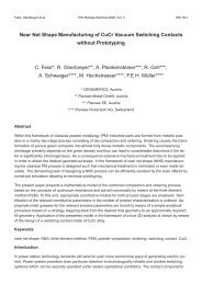
Near Net Shape Manufacturing of CuCr Vacuum Switching Contacts ...
Near Net Shape Manufacturing of CuCr Vacuum Switching Contacts ...
Near Net Shape Manufacturing of CuCr Vacuum Switching Contacts ...

Create successful ePaper yourself
Turn your PDF publications into a flip-book with our unique Google optimized e-Paper software.
Feist, Oberbreyer et al. 17th Plansee Seminar 2009, Vol. 3 WS 15/1<br />
<strong>Near</strong> <strong>Net</strong> <strong>Shape</strong> <strong>Manufacturing</strong> <strong>of</strong> <strong>CuCr</strong> <strong>Vacuum</strong> <strong>Switching</strong> <strong>Contacts</strong><br />
Abstract<br />
without Prototyping<br />
C. Feist*, R. Oberbreyer**, A. Plankensteiner***, R. Grill***,<br />
A. Schwaiger****, M. Hochstrasser****, F.E.H. Müller****<br />
* CENUMERICS, Austria<br />
** Plansee Metall GmbH, Austria<br />
*** Plansee SE, Austria<br />
**** Plansee Powertech AG, Switzerland<br />
Within the framework <strong>of</strong> classical powder metallurgy (PM) industrial parts are formed from metallic powders<br />
in a mainly two-stage process consisting <strong>of</strong> die-compaction and sintering. Sintering causes the transformation<br />
<strong>of</strong> porous green compacts into almost fully dense metallic components. The accompanying<br />
shrinkage primarily depends on the green density and thus can lead to considerable distortions if the latter<br />
is significantly inhomogeneous. As a consequence extensive mechanical treatment has to be applied<br />
in order to obtain the desired geometrical shape. In the framework <strong>of</strong> near net shape (NNS) manufacturing<br />
the classical PM process is designed such that mechanical treatment is minimized or even made obsolete.<br />
The demanding task <strong>of</strong> designing a NNS process can be efficiently assisted by the tools <strong>of</strong>fered by<br />
numerical simulation allowing to minimize prototyping.<br />
The present paper presents a mathematical model <strong>of</strong> the combined compaction and sintering process<br />
based on the concepts <strong>of</strong> continuum mechanics and solved numerically by means <strong>of</strong> the finite element<br />
method (FEM). To this end, appropriate constitutive models for both process stages are employed. Identification<br />
<strong>of</strong> the relevant constitutive parameters in the context <strong>of</strong> powder characterization is outlined. Appropriate<br />
initial guesses for the relevant process parameters are found by means <strong>of</strong> a simple analytical<br />
procedure based on a strategy stepping-back from the desired final geometry to an approximate required<br />
fill geometry. Application <strong>of</strong> the presented model in the framework <strong>of</strong> a true 3D-analysis is shown by means<br />
<strong>of</strong> the design <strong>of</strong> a switching contact made <strong>of</strong> <strong>CuCr</strong> alloy.<br />
Keywords<br />
near net shape, NNS, finite element method, FEM, powder compaction, sintering, switching contact, <strong>CuCr</strong><br />
Introduction<br />
In power station technology demands still exist for even more economical ways <strong>of</strong> generating electric current.<br />
Power system providers draw particular attention to technologically reliable and durable switching<br />
systems which can be securely operated under severe operational conditions. The contact components
WS 15/2 17th Plansee Seminar 2009, Vol. 3 Feist, Oberbreyer et al.<br />
form the main part <strong>of</strong> breaking chambers and high performance materials have to be specifically developed<br />
for the use <strong>of</strong> these components in vacuum and arcing contact systems.<br />
Over the past two decades <strong>CuCr</strong> based contact materials have become established for use with contactors<br />
and circuit breakers, respectively, in vacuum interrupters for the medium voltage range <strong>of</strong> 1 kV to<br />
72.5 kV. Generally speaking <strong>CuCr</strong> contact materials provide a combination <strong>of</strong> high current breaking capacity,<br />
dielectric strength <strong>of</strong> the open contact gap and long service life-time <strong>of</strong> up to 10,000 operations at<br />
the rated current.<br />
Depending on the application field <strong>of</strong> the <strong>CuCr</strong> contact component the Cr content typically varies between<br />
about 20 wt.% and 60 wt.% with the lower range applying to operational conditions where high arc quenching<br />
and low current chopping play a significant role and the higher range applying where high erosion resistance<br />
as well as a proper welding behavior come into focus. Beside the choice for an adequate <strong>CuCr</strong><br />
grade the geometrical features <strong>of</strong> the contact component also play a significant role on the performance<br />
during switching operations.<br />
<strong>CuCr</strong> contact components are manufactured via a powder metallurgical processing route which includes<br />
mixing <strong>of</strong> the Cu and Cr powders, die compaction <strong>of</strong> the powder blend to a green body and sintering typically<br />
below the melting point <strong>of</strong> copper. After sintering <strong>CuCr</strong> contact materials may exhibit a small amount<br />
<strong>of</strong> retained porosity. By further reduction <strong>of</strong> porosity after sintering, i.e. by repressing, the electrical, thermal,<br />
and mechanical properties <strong>of</strong> the contact material can be improved. A principal description <strong>of</strong> the<br />
influence <strong>of</strong> the Cr content on the microstructure <strong>of</strong> the <strong>CuCr</strong> material and its implications on the operational<br />
behavior <strong>of</strong> the contact component can be found in [1].<br />
Within the classical powder metallurgical manufacturing approach <strong>of</strong> die compaction and sintering shape<br />
chipping and other types <strong>of</strong> mechanical treatment cannot be avoided in order to get the desired final shape<br />
<strong>of</strong> the contact component. This is mainly due to an inhomogeneous spatial density distribution in the diepressed<br />
green body which governs the spatial gradient in sinter density. This way sinter shrinkage along<br />
with sinter distortions have to be handled properly when defining the design <strong>of</strong> pressing tools and pressing<br />
kinematics. Because <strong>of</strong> an a priori unknown functional dependence between final shape/dimensions<br />
<strong>of</strong> the sintered body, ingoing powder material characteristics and the die compaction/sinter process parameters,<br />
respectively, an iterative strategy has to be applied in practice covering materials development,<br />
design <strong>of</strong> processing, and performance <strong>of</strong> field tests. As long as mechanical treatment <strong>of</strong> the contact<br />
component is chosen for obtaining the final shape <strong>of</strong> the component empirical knowledge on the interaction<br />
between material characteristics, process parameters, and the quality relevant parameters <strong>of</strong> the<br />
sintered product is widely being pro<strong>of</strong>ed to be sufficient for a successful product development. However,<br />
economically more challenging tasks such as minimization or even complete prevention <strong>of</strong> material to be<br />
machined <strong>of</strong>f aim at reducing material and manufacturing costs as well as optimizing the time-to-market<br />
characteristics. Commonly such strategies are referred to as near net shape manufacturing (NNS) which<br />
typically make use <strong>of</strong> advanced tools for numerical simulation <strong>of</strong> the NNS process chain and advanced<br />
material characterization methods. Whereas the latter are intended for extracting material parameters for<br />
the material laws describing the constitutive behavior <strong>of</strong> powder materials and sintered materials under<br />
die-pressing and sintering operations, respectively, the numerical simulation tools are intended for performing<br />
efficiently numerical experiments <strong>of</strong> the NNS process chain aiming at reducing overall costs in<br />
establishing an experimentally and numerically verified prototype for the NNS process chain.
Feist, Oberbreyer et al. 17th Plansee Seminar 2009, Vol. 3 WS 15/3<br />
Finite element modeling <strong>of</strong> PM process-chain<br />
The numerical simulation <strong>of</strong> the PM process-chain is based on the finite element method (FEM) and the<br />
concepts <strong>of</strong> continuum mechanics. To this end all powder-material forming the designed part is modeled<br />
as a continuous domain through the entire process-chain starting from the beginning <strong>of</strong> powdercompaction<br />
till the end <strong>of</strong> sintering. Furthermore the simulation relies on a phenomenological description<br />
<strong>of</strong> the material response (constitutive modeling) with respect both to compaction and sintering.<br />
The simulation primarily aims at predicting the deformation-state u(x) <strong>of</strong> this domain at any stage as well<br />
as its density-distribution ρ(x). In addition, the stress-state σ(x) found in the powder-domain can be assessed<br />
in order to detect critical states during the compaction and ejection phase.<br />
FE-analyses <strong>of</strong> the process-chain start with compaction <strong>of</strong> the powder-domain. This implies that the fillstate<br />
described by the geometry <strong>of</strong> the fill-body and the fill-density distribution have to be explicitly given<br />
for the analysis. Procedures to implicitly obtain the fill state based on simulation can be found e.g. in the<br />
framework <strong>of</strong> discrete element method (DEM) [2], which is not covered within the present work.<br />
Numerical modeling <strong>of</strong> the PM process-chain requires two principal analysis-steps: (i) analysis <strong>of</strong> powder<br />
compaction and ejection <strong>of</strong> the green-compact and (ii) analysis <strong>of</strong> sintering <strong>of</strong> the green-compact. The<br />
provided basic distinction is necessary since the driving mechanisms are different in both stages. In order<br />
to provide a continuous work-flow, results obtained from the first analysis step (in terms <strong>of</strong> the deformed<br />
geometry and the corresponding green density distribution ρg(x)) are imported as an initial state for the<br />
second analysis step.<br />
Analysis <strong>of</strong> powder compaction and ejection also requires a mathematical representation <strong>of</strong> the employed<br />
tools. The latter are usually considered as rigid surface representations <strong>of</strong> the tools’ surfaces in contact to<br />
the powder.<br />
Constitutive modeling <strong>of</strong> powder-compaction<br />
The nonlinear mechanical behavior <strong>of</strong> granular materials under predominantly triaxial compressive stress<br />
states can be described in a phenomenological manner employing a cap-model formulated in the framework<br />
<strong>of</strong> theory <strong>of</strong> plasticity [3]. Its cap-shaped yield surface is formulated in the hydrostatic-deviatoric<br />
stress-space p - q with p = − 1<br />
3<br />
tr(σ) as the hydrostatic stress (i.e. the first invariant <strong>of</strong> stress tensor σ)<br />
and q = � 3/2 s : s as the VON MISES equivalent stress (i.e. the second invariant <strong>of</strong> stress tensor σ with<br />
s denoting the deviatoric stress tensor). As usual in mechanics <strong>of</strong> soils and other granular materials, the<br />
hydrostatic pressure stress is considered as positive for compressive stress states.<br />
The elliptical cap-surface fc (Fig. 1a) is formally given as<br />
fc = � (p − pa) 2 + (R q) 2 − R qa<br />
where pa and qa denote the hydrostatic pressure and the VON MISES equivalent stress, respectively, associated<br />
to the center and the apex <strong>of</strong> the elliptical cap and R defines the eccentricity <strong>of</strong> the cap. The intercept<br />
<strong>of</strong> the cap-surface with the hydrostatic pressure axis is then given as<br />
(1)<br />
pb = pa + R qa. (2)<br />
The cap surface limits compressive stress-states with high values <strong>of</strong> triaxiality p/q as found especially for
WS 15/4 17th Plansee Seminar 2009, Vol. 3 Feist, Oberbreyer et al.<br />
q<br />
Drucker-Prager<br />
shear-failure surface<br />
d<br />
1<br />
tan β<br />
elastic domain (E, )<br />
p a<br />
elliptical cap-surface<br />
p b<br />
R (d + p a tan ß)<br />
p<br />
q a = d + p a tanß<br />
(a) (b)<br />
Figure 1: Combined DRUCKER-PRAGER-cap plasticity model: (a) yield surface in the hydrostatic-deviatoric stress-space, (b) evolution<br />
<strong>of</strong> the yield surface with respect to density.<br />
compaction processes as die compaction. However, the cap surface is not suited for describing the response<br />
under stress-states with lower values <strong>of</strong> triaxiality. Such stress states take place in the green compact<br />
especially during the ejection phase but might occur also during compaction with more complex toolgeometries.<br />
Such stress states might lead to the formation <strong>of</strong> discontinuities and cracks in the powderbody<br />
being compacted and hence should be avoided. Thus, for the simulation <strong>of</strong> the compaction process<br />
it is desirable to be able to assess such stress-states in order to identify critical regions or process stages.<br />
To account for respective stress states the cap-surface is combined with a shear-failure surface fs. In the<br />
most simple case the well-known cone-shaped DRUCKER-PRAGER yield-surface (Fig. 1a) given as<br />
q<br />
¡0<br />
p ¡ ¡<br />
fs = q − p tanβ − d (3)<br />
can be used with d and β as the cohesive strength and the angle <strong>of</strong> internal friction <strong>of</strong> the material, respectively.<br />
With fc and fs considered to intersect at pa, ellipse-axis qa in (1) can be expressed as<br />
qa = d + pa tanβ. (4)<br />
It has to be noted that the employed shear-failure surface represents a valid representation <strong>of</strong> the mechanical<br />
response only for stress states with positive triaxiality values. However, it does not properly account<br />
for three-dimensional tensile stress states which is out <strong>of</strong> scope <strong>of</strong> the employed model in the context<br />
<strong>of</strong> powder compaction.<br />
With respect to the hardening law it is assumed that the cap-surface fc exhibits hardening representing<br />
the behavior <strong>of</strong> the metallic powder under hydrostatic compression. To this end, the cap-apex value pb (2)<br />
is related to the logarithmic volumetric strain<br />
εv = ε el<br />
v + ε pl<br />
v<br />
consisting <strong>of</strong> a (reversible) elastic part ε el<br />
v and a (irreversible) plastic part ε pl<br />
v . The total volumetric strain εv<br />
in turn can be expressed in terms <strong>of</strong> the current material density ρ as<br />
� �<br />
ρ<br />
εv = ln<br />
ρ0<br />
(5)<br />
(6)<br />
¡th
Feist, Oberbreyer et al. 17th Plansee Seminar 2009, Vol. 3 WS 15/5<br />
with ρ0 as the reference density <strong>of</strong> the material (i.e. the density <strong>of</strong> the powder in loose packing). Since the<br />
contribution <strong>of</strong> the elastic part in (5) is <strong>of</strong> a few orders less than the one from the plastic part, in general it<br />
can be neglected, such that<br />
Hardening <strong>of</strong> the cap-surface can then be formally defined as<br />
� �<br />
ρ<br />
εv = ln ≈ ε<br />
ρ0<br />
pl<br />
v . (7)<br />
pb = fh (εv) (8)<br />
where fh represents a C 1 -continuous, monotonously increasing hardening function appropriate for describing<br />
the compaction behavior <strong>of</strong> the powder under consideration. In general, power or exponential<br />
type functions can be successfully employed.<br />
It can be seen from experiments that the cap-surface will not keep its shape under compressive loading,<br />
such that the cap-eccentricity parameter R in (1) also has to be made dependent on the volumetric strain.<br />
Furthermore, compaction <strong>of</strong> granular material is accompanied by a significant increase in the strength <strong>of</strong><br />
the material defined by the shear-failure parameters d and β in (3). Hence, parameters R, d and β are<br />
formally related to the volumetric strain and the density <strong>of</strong> the material as<br />
R = fR (εv)<br />
d = fd (εv)<br />
β = fβ (εv). (9)<br />
Appropriate evolution functions must be chosen and their coefficients adapted in order to fit experimental<br />
results for the particular powder under consideration. The evolution <strong>of</strong> the combined DRUCKER-PRAGERcap<br />
surface based on evolution-equations (8) and (9) are shown for an exemplary powder in Fig. 1b.<br />
Together, the convex cap-surface fc = 0 and the shear-failure surface fs = 0 confine the elastic domain<br />
(Fig. 1a). For stress-states within this domain isotropic elastic behavior expressed by the constants<br />
<strong>of</strong> elasticity E and ν is assumed to be valid. In order to be able to numerically capture the elastic springback<br />
taking place during the ejection phase <strong>of</strong> a green compact it is also necessary to describe the densitydependence<br />
<strong>of</strong> the modulus <strong>of</strong> elasticity E again formally expressed in terms <strong>of</strong> the volumetric strain as<br />
Constitutive modeling <strong>of</strong> sintering<br />
E = fE (εv). (10)<br />
Sintering is a heat-treatment process conducted at high-temperatures that causes the powder-particles<br />
within the porous green compact to be bonded together. Since the volume <strong>of</strong> the pores between the powder-particles<br />
is reduced during this process, the material shrinks and consequently its density is increased.<br />
A constitutive model describing the mechanical behavior <strong>of</strong> a solid being sintered for usage in the context<br />
<strong>of</strong> simulations <strong>of</strong> the PM process-chain must be able to reproduce both evolution <strong>of</strong> density and shrinkage<br />
as shown for two different <strong>CuCr</strong>-alloys by results from sintering experiments in Fig. 2. Hence, it is<br />
sufficient to again resort to a purely phenomenological model, which however is derived from a micromechanical<br />
description <strong>of</strong> inter-particle interactions [4, 5].
WS 15/6 17th Plansee Seminar 2009, Vol. 3 Feist, Oberbreyer et al.<br />
sinter density £s [g/cm³]<br />
8.5<br />
8.0<br />
7.5<br />
7.0<br />
6.5<br />
6.0<br />
5.5<br />
¢th <strong>CuCr</strong> alloy 1<br />
¢th <strong>CuCr</strong> alloy 2<br />
<strong>CuCr</strong> alloy 1<br />
<strong>CuCr</strong> alloy 2<br />
lin. regr. <strong>CuCr</strong> alloy 1<br />
lin. regr. <strong>CuCr</strong> alloy 2<br />
5.0 5.5 6.0 6.5 7.0 7.5 8.0 8.5<br />
¢g green density [g/cm³]<br />
axial shrinkage ¤z [%]<br />
5.0<br />
4.0<br />
3.0<br />
2.0<br />
1.0<br />
0.0<br />
5.0 5.5 6.0 6.5 7.0 7.5 8.0 8.5<br />
¢g green density [g/cm³]<br />
5.0 5.5 6.0 6.5 7.0 7.5 8.0 8.5<br />
¢g green density [g/cm³]<br />
(a) (b) (c)<br />
Figure 2: Results obtained from sintering experiments for two types <strong>of</strong> <strong>CuCr</strong> alloy – green-density (ρg) dependence <strong>of</strong> (a) sinter<br />
density ρs, (b) axial sinter shrinkage εz and (c) radial sinter shrinkage εr.<br />
An appropriate constitutive model can be found in the framework <strong>of</strong> the theory <strong>of</strong> visco-elasticity formulated<br />
for the sintering behavior as<br />
˙ε = S (σ − Iσs), (11)<br />
where the strain-rate tensor ˙ε is related to the stress tensor σ and the sintering stress σs using the inverse<br />
viscosity tensor S.<br />
In the general form <strong>of</strong> (11) the inverse viscosity tensor can represent isotropic as well as general anisotropic<br />
behavior. For isotropic behavior the inverse viscosity tensor can be formulated in terms <strong>of</strong> the bulk<br />
and shear viscosities K = f(ρ) and G = f(ρ), for which micro-mechanical relationships have been<br />
derived [4]. For the <strong>CuCr</strong> powders under consideration in the present work, a more or less significant<br />
anisotropy (transversal isotropy to be more precise) can be observed (Fig. 2b and c): isotropic behavior<br />
can be found within the plane normal to the compaction-axis, whereas sintering strains in the compactionaxis<br />
are significantly different. In the general case <strong>of</strong> anisotropic behavior the components <strong>of</strong> the viscosity<br />
– as found from the micro-mechanically derived bulk<br />
and shear viscosities K and G – using the viscosity ratio [6]<br />
tensor Sij can be related to the isotropic term S iso<br />
ij<br />
ϕij = Sij<br />
radial shrinkage ¤r [%]<br />
5.0<br />
4.0<br />
3.0<br />
2.0<br />
1.0<br />
0.0<br />
Siso. (12)<br />
The viscosity ratios in general will evolve during the sintering process [6]. As observed from sintering experiments<br />
the ratio <strong>of</strong> anisotropy obviously depends on the green density (i.e. the initial density <strong>of</strong> the sintering<br />
process). Hence, the viscosity ratios depend both on the initial density (i.e. green density) ρ0 = ρg<br />
and the current density ρ and formally are given as<br />
ij<br />
ϕij = fϕ (ρ0, ρ). (13)<br />
From sintering experiments one can determine the density ρs attainable through sintering for which<br />
ρg < ρs = f(ρg) < ρth<br />
(14)
Feist, Oberbreyer et al. 17th Plansee Seminar 2009, Vol. 3 WS 15/7<br />
holds with ρth as the theoretical density <strong>of</strong> the (pore-free) solid material and the sinter density depending<br />
on the green density ρg. Hence, it is convenient to relate all density measures used in the evolution<br />
equations <strong>of</strong> the viscosities and viscosity ratios to the current relative density with respect to the attainable<br />
sinter density d = ρ/ρs.<br />
The evolution equations both <strong>of</strong> the isotropic components <strong>of</strong> the inverse viscosity tensor S iso<br />
ij (expressed<br />
in terms <strong>of</strong> the bulk and shear viscosities K and G) and the viscosity ratios are now formulated in terms <strong>of</strong><br />
the relative density serving as an internal variable for the model. Under the assumption <strong>of</strong> mass-conser-<br />
vation its evolution is given as<br />
˙<br />
d = −d tr (˙ε). (15)<br />
with d = 1 indicating a fully sintered state (equivalent to reaching the attainable sinter density ρs).<br />
Powder-characterization, tests and calibration<br />
A prerequisite for successful FE analyses <strong>of</strong> PM processes based on the described mathematical model<br />
is the identification <strong>of</strong> the involved constitutive parameters and their dependence on the density <strong>of</strong> the<br />
powder. This identification – termed as powder-characterization – is usually done on an experimental<br />
basis and will be outlined in the following by means <strong>of</strong> the constitutive parameters required for the compaction<br />
analysis.<br />
For the mechanical description <strong>of</strong> die-compaction it is most important to have reliable experimental data<br />
describing the relationship between the uniaxial compaction stress σz and the green density ρg or the<br />
volumetric plastic strain εv, respectively. These data can be obtained from rather simple die-compaction<br />
experiments on small cylindrical samples (Fig. 3a, (1)). The stress state during die-compaction exhibits<br />
high triaxialities, and hence will lie on the cap-surface, however considerably <strong>of</strong>f the p-axis. From the obtained<br />
relationship together with the imposed geometrical requirement that the cap- and the shear-failure<br />
surface (to be determined later) will intersect at pa (Fig. 1a) one can determine the associated relationship<br />
between the cap-apex pb and the volumetric plastic strain εv (i.e. the hardening relationship <strong>of</strong> the<br />
cap-surface) as (8). A more accurate alternative for compaction processes with triaxialities p/q → ∞ can<br />
be found by conducting triaxial compaction tests (Fig. 3a, (2)) with p/q = ∞, which directly provide the<br />
hardening relationship (8).<br />
For reliable results <strong>of</strong> the ejection-phase and stress-states at critical regions in the powder-domain during<br />
compaction it is crucial to be able to predict the onset <strong>of</strong> failure by means <strong>of</strong> the shear-failure surface<br />
fs (3). For a certain density state it is described by the cohesive strength d and the angle <strong>of</strong> internal friction<br />
β (Fig. 3a). In order to identify these parameters at least two types <strong>of</strong> experiments at different levels<br />
<strong>of</strong> triaxiality have to be conducted [3]: to this end, most <strong>of</strong>ten the brazilian disc test (Fig. 3a, (3)) and the<br />
uniaxial compression test (Fig. 3a, (4)) are employed. These tests are conducted again on small cylindrical<br />
samples previously compacted to approximately the same density. The stress states found in the<br />
specimens can be calculated analytically from the applied load. Hence, from the maximum applicable<br />
load at incipient failure <strong>of</strong> the samples one can easily determine the stress-invariants pf and qf associated<br />
to the failure-state. Consequently, the stress-point pf, qf is located on the shear-failure surface fs<br />
(Fig. 3a) (Remarks: It is assumed that no significant strain-hardening precedes failure <strong>of</strong> the sample and<br />
that only detection <strong>of</strong> incipient failure but not resolution <strong>of</strong> its propagation is to be covered which in turn<br />
justifies the assumption <strong>of</strong> perfect plasticity for the shear-failure surface.). From the failure stress-states<br />
obtained from the employed tests one can derive the shear-failure surface as a linear regression defined<br />
by the cohesive strength d and the angle <strong>of</strong> internal friction β. If an additional type <strong>of</strong> experiment at a dif-
WS 15/8 17th Plansee Seminar 2009, Vol. 3 Feist, Oberbreyer et al.<br />
(5)<br />
q<br />
(3)<br />
d<br />
(4)<br />
tan β<br />
1<br />
p a<br />
ferent level <strong>of</strong> triaxiality is used (e.g. a four-point bending test, Fig. 3a, (5)) determination <strong>of</strong> the strength<br />
parameters becomes over-determine which can help reducing potential errors by means <strong>of</strong> least-squareroot<br />
minimization. Alternatively, a higher order shear-failure surface could be determined from these test.<br />
¥<br />
p b<br />
(1)<br />
p<br />
(2)<br />
d<br />
d 2<br />
d 3<br />
d1 ¥0<br />
¥2<br />
¥3¥th<br />
(a) (b)<br />
Figure 3: Mechanical powder-characterization: (a) experimental determination <strong>of</strong> cap- and shear-failure surface parameters,<br />
(b) density dependence <strong>of</strong> cohesive strength d.<br />
The obtained shear-failure surface (in terms <strong>of</strong> d and β) is only valid for the given density-level ρ1 (Fig. 3).<br />
In order to determine the density-dependence <strong>of</strong> the strength parameters similar tests must be conducted<br />
at various other density levels ρ2, ρ3 . . . (Fig. 3b) relevant for PM production purposes. The obtained discrete<br />
values d1, d2 . . . and β1, β2 . . . for simulation purposes will be fitted using an appropriate regressionfunction<br />
(9b, c) (see Fig. 3b in case <strong>of</strong> cohesion d), which will be used to interpolate or extrapolate the<br />
strength parameters at any density ρ.<br />
Analytical assessment <strong>of</strong> PM-processed parts<br />
When designing the process-plan for a component to be produced on the PM manufacturing route the<br />
designer is mainly confronted with the question on how to arrive at the final nominal geometry. In particular<br />
he has to determine all relevant process-parameters like the geometry <strong>of</strong> the die, the fill-height <strong>of</strong><br />
the powder-body, the required powder mass, the tools, their travel during compaction, the remaining axial<br />
force during ejection etc. This in most <strong>of</strong> the cases is done on a combined basis <strong>of</strong> experience and trialand-error<br />
approaches.<br />
In this respect, finite element analyses based on the described mathematical model can only help in accelerating<br />
the iterative trial-and-error procedure by virtually conducting the required experiments. However,<br />
also for the numerical simulations the process-parameters as given above have to be explicitly estimated<br />
or prescribed, respectively. This follows from the fact that the described mathematical model exactly<br />
represents the manufacturing process and follows the direction <strong>of</strong> its work-flow.<br />
In this context it is desirable to obtain appropriate initial estimates for the process-parameters serving as<br />
a valid initial guess for numerically simulated or experimentally conducted process-experiments. These<br />
initial estimates in principle should be obtained by starting from the nominal geometry <strong>of</strong> the component<br />
and stepping the entire process-chain right back to the fill-state. Through the irreversible character <strong>of</strong> the<br />
mathematical relationships employed for describing the constitutive state both in the compaction and sintering<br />
step, this however is only possible for very simple geometries based on analytical solutions under<br />
some assumptions:
Feist, Oberbreyer et al. 17th Plansee Seminar 2009, Vol. 3 WS 15/9<br />
To this end, it is assumed that the density is homogeneous across the entire domain at any process-time.<br />
Since any friction taking place between the tools and the powder will preclude this assumption to hold, a<br />
frictionless state µ = 0 is assumed. Furthermore, it is assumed that the considered part will not change<br />
its topology during the entire process – however, it can change its size and its proportions (e.g. a cylindrical<br />
part will remain cylindrical, however, with changing diameter d and height h and changing ratio d/h).<br />
Under this assumption one can easily derive a step-back procedure as outlined below for geometric primitives<br />
as cubes, cones or cylinders. More complex geometries can be assembled from these primitives<br />
allowing the determination <strong>of</strong> initial guesses for process-parameters also for industrial components.<br />
For the sake <strong>of</strong> simplicity, the further outline is done by means <strong>of</strong> a single cylindrical part. The procedure<br />
starts by defining the nominal geometry <strong>of</strong> the part at the end <strong>of</strong> sintering given by its diameter ds and<br />
height hs, hence determining its volume Vs. In addition an approximate fill density ρf and a desired green<br />
density ρg have to be assumed – on the basis <strong>of</strong> the chosen green density the required axial compactionload<br />
Fz can be determined later and compared to the specifications <strong>of</strong> the press available for production.<br />
Hence, the chosen green density will become an adaptable parameter for the design. On basis <strong>of</strong> the selected<br />
green density the attainable sinter density ρs can be computed together with the radial and axial<br />
sinter strains εr and εz (cf. Fig. 2). Using the computed sinter density ρs and the given volume Vs one can<br />
determine the total mass m <strong>of</strong> the part. By reversely applying the sinter strains to the final geometry the<br />
geometrical parameters at the start <strong>of</strong> the sintering phase (i.e. the green state) dg and hg can be found.<br />
For the given green density ρg and the associated volumetric plastic strain εv (5) all constitutive parameters<br />
<strong>of</strong> the cap-plasticity model can be computed employing their evolution equations (8), (9) and (10).<br />
Hence, the constitutive state at the end <strong>of</strong> the compaction phase is fully given and the associated stress<br />
state in terms <strong>of</strong> the axial and radial stress σz and σr can be computed. Using the diameter <strong>of</strong> the green<br />
compact dg the maximum axial load Fz required for compaction can be found and compared to the load<br />
available with the press used within the later production.<br />
Using this stress state the radial and axial elastic deformations during the ejection-phase can be esti-<br />
mated in terms <strong>of</strong> the radial and axial elastic strains ε el<br />
r and ε el<br />
z using the density-dependent Young’s modulus<br />
(10). By reversely applying these strains on the green-compact geometry one arrives at the height hp<br />
and diameter dp <strong>of</strong> the powder-domain in the compacted state associated to the maximum compactionload.<br />
Diameter dp now must equal the diameter <strong>of</strong> the used die and consequently the diameter <strong>of</strong> the fillbody<br />
df .<br />
Postulating conservation <strong>of</strong> powder-mass m the fill volume Vf can be computed using fill-body diameter<br />
df and consequently its fill-height hf .<br />
Summarizing the outlined procedure it allows to determine appropriate initial estimates for the relevant<br />
process-parameters in the following principle<br />
given : ds, hs<br />
estimate : ρf, ρg<br />
determine : ρs, m, dg, hg, df, hf, Fz<br />
One <strong>of</strong> the most critical phases <strong>of</strong> the process-chain is certainly the ejection stage, where the compact radially<br />
constrained by the die is gradually turned to an unconstrained state. It is a common procedure to either<br />
keep a fixed residual axial load on the punches during ejection (load-control) or to keep the distance<br />
between the lower and upper punches fixed (displacement-control). Selecting an appropriate level <strong>of</strong> the<br />
associated process-parameters is a crucial feature for successful ejection: the application <strong>of</strong> a residual<br />
(16)
WS 15/10 17th Plansee Seminar 2009, Vol. 3 Feist, Oberbreyer et al.<br />
load will move the stress-state from the regime <strong>of</strong> high triaxialities to low ones, hence risking possible<br />
failure with stress states moving towards the shear-failure surface (3). In this context the given analytical<br />
procedure can also help to give estimates for the maximum applicable residual load based on the stress<br />
state due to the residual load and the density-dependent strength parameters d and β (3).<br />
Application <strong>of</strong> numerical model to <strong>CuCr</strong> switching contacts<br />
Application <strong>of</strong> the mathematical model for the NNS PM process-chain as described in the previous sections<br />
will be shown in the following by means <strong>of</strong> a switching contact made <strong>of</strong> a <strong>CuCr</strong> alloy.<br />
The preliminary final nominal geometry <strong>of</strong> the part under consideration is shown in Fig. 4a, where for illustration<br />
purposes one quarter is cut away. The part is formed by a circular disc with a diameter and<br />
height <strong>of</strong> app. 46 mm and 5 mm, respectively. The outer section is slightly tapered with an angle <strong>of</strong> app.<br />
3.5 ◦ and all edges are rounded. In view <strong>of</strong> the application requirements the part contains four non-radial,<br />
straight slots <strong>of</strong> 5 mm width each with a cylindrical base, imposing a fourfold cyclic-symmetry. For the<br />
contact to be placed between adjacent adapter parts sunk holes with a depth <strong>of</strong> 1.5 and 1.0 mm are arranged<br />
on both sides.<br />
Die-compaction is done on a press with multilevel lower and upper punches. Hence, ring-shaped, outer<br />
punches are used for forming the cross-sectional contour <strong>of</strong> the part, whereas circularly shaped, inner<br />
punches can be used to form the sunk holes. Separate control <strong>of</strong> the inner and outer punches allows to<br />
uniformly compact the distinct sections <strong>of</strong> the contact, thus reducing green-density gradients. The upper<br />
outer punch is inclined in order to form the cone-shaped outer cross-section. Compaction is done using<br />
an unseparated die and formation <strong>of</strong> the slots is established using four slot-punches.<br />
The process-plan is pre-designed using the analytical procedure as given in the previous section. Based<br />
on its results a numerical model <strong>of</strong> the powder-body in fill state is established. Exploiting the cyclic-symmetric<br />
character only one fourth has to be modeled and appropriate coupling constraints have to be imposed<br />
to the symmetry planes. The latter can be chosen quite arbitrarily as long as reproduction <strong>of</strong> the<br />
full part is ensured: in order to prevent numerical difficulties during the later analysis it is convenient to<br />
select planes that do not intersect the slot-punches. In order to obtain an almost uniform green-density<br />
upper sunk hole<br />
lower sunk hole<br />
slot<br />
upper outer punch<br />
upper inner punch<br />
(a) (b)<br />
die<br />
lower outer punch<br />
slot-punch<br />
lower inner punch<br />
fill-body<br />
Figure 4: <strong>Switching</strong> contact made <strong>of</strong> <strong>CuCr</strong> alloy: (a) preliminary final nominal geometry with main features, (b) finite element<br />
model <strong>of</strong> fill-body and tools.
Feist, Oberbreyer et al. 17th Plansee Seminar 2009, Vol. 3 WS 15/11<br />
distribution it is decided to design both sunk-holes with identical diameter. In addition, for the analysis the<br />
geometry is simplified by neglecting all fillets except for the base-fillet <strong>of</strong> the slot-punches. The FE-model<br />
consisting <strong>of</strong> the fill body meshed with linear hexahedron elements and the tools modeled as rigid surfaces<br />
is depicted in Fig. 4b. The model reproduces the fill-body assuming it in a state after a first powdertransfer<br />
established by the inner punches forming the initial cavity <strong>of</strong> the upper sunk-hole (the powdertransfer<br />
itself could be numerically resolved only with a high numerical effort using adaptive procedures<br />
which is out <strong>of</strong> scope <strong>of</strong> the present work). A uniform fill-density ρf(x) = const is prescribed for the entire<br />
fill-body. Contact interactions are imposed between the surfaces <strong>of</strong> the powder-body and the tools. The<br />
upper edges <strong>of</strong> the dies are filleted or chamfered, respectively, in order to allow smooth ejection <strong>of</strong> the<br />
green-compact. All simulations are carried out using the commercial finite element code Abaqus [7].<br />
As a first step the inclined upper outer punch is brought into full contact with the powder leading to slightly<br />
higher densities at the outer perimeter <strong>of</strong> the part. Afterwards both outer punches are driven against each<br />
other ensuring most minimal effects related to friction against the die. Simultaneously, the inner punches<br />
move against one another, however, with a reduced height <strong>of</strong> travel, thus preventing powder-transfer between<br />
the inner and outer section and ensuring an almost uniform density-distribution. After full compaction<br />
the upper punches are slightly released before the part is ejected and the punches are finally removed.<br />
The model now represents the state <strong>of</strong> the unloaded green-compact and the initial state <strong>of</strong> the sinteringprocess<br />
as shown in Fig. 5a. The latter can then be simulated employing the deformed mesh associated<br />
to the end <strong>of</strong> the compaction-simulation. Besides, the green-density distribution ρg(x) serves as additional<br />
input to the sintering-simulation. For the sintering-simulation only appropriate statically determine<br />
and constraint-free support-conditions have to be provided, however, no additional parts or tools have to<br />
be considered.<br />
Results in terms <strong>of</strong> the obtained relative density measures (with respect to the theoretical density <strong>of</strong> the<br />
alloy) are shown in Fig. 5 both for the green-state (a) as well for the fully sintered state (b). Deviations<br />
from the simplified final nominal geometry ∆n are given in Fig. 5c in terms <strong>of</strong> oversize (+) and undersize<br />
(-). It can be seen that the maximum geometrical deviations are about 0.8 mm taking place at the<br />
finger-like acute-angled piece along the slot. This can be explained by the slight over-compaction taking<br />
place in this region as a consequence <strong>of</strong> a dead-water-effect during compaction (i.e. the powder is not<br />
allowed to flow in circumferential direction). However, for most <strong>of</strong> the part maximum deviations <strong>of</strong> app.<br />
0.1 mm can be observed. The obtained geometrical deviations now serve as a basis for respective adjustments<br />
<strong>of</strong> the relevant process-parameters in order to obtain the desired final geometry complying<br />
to the required tolerances and exhibiting almost uniform density-distributions. To this end, an iterative<br />
scheme is applied based on the numerical model until the geometrical requirements are met.<br />
d g [-] d s [-] ¦n [mm]<br />
1.0<br />
0.8<br />
(a)<br />
1.0<br />
0.9<br />
+0.8<br />
-0.2<br />
(b) (c)<br />
Figure 5: Selected results <strong>of</strong> PM analysis for a switching contact: (a) relative density after compaction, (b) relative density after<br />
sintering, (b) geometrical deviation from simplified nominal geometry.
WS 15/12 17th Plansee Seminar 2009, Vol. 3 Feist, Oberbreyer et al.<br />
Summary<br />
A mathematical model dedicated to numerically resolve the traditional PM process-chain – consisting <strong>of</strong><br />
die-compaction and sintering – by means <strong>of</strong> the finite element method (FEM) was presented. The model<br />
relies on the concepts <strong>of</strong> continuum mechanics and describes the constitutive response using a combined<br />
DRUCKER-PRAGER-cap plasticity model and an anisotropic visco-elastic model for the compaction- and<br />
sintering-stage, respectively. Development and application <strong>of</strong> the model is motivated by the demands for<br />
near net shape (NNS) manufacturing <strong>of</strong> parts reducing or making subsequent mechanical treatment almost<br />
obsolete. The numerical model allows for fast and relatively cheap evaluation <strong>of</strong> different processplans<br />
and optimization to achieve the demands <strong>of</strong> NNS-products.<br />
The mathematical model was outlined with an emphasis on the employed constitutive models. Determination<br />
<strong>of</strong> the relevant constitutive properties in the framework <strong>of</strong> powder-characterization was covered<br />
subsequently. In order to determine appropriate initial guesses for the relevant process-parameters based<br />
on the identified material behavior an analytical procedure was presented. Its results can be used both for<br />
subsequent experimental as well as virtually conducted compaction-tests.<br />
Application <strong>of</strong> the numerical model and the analytical procedure was finally given by means <strong>of</strong> a switching<br />
contact part made <strong>of</strong> <strong>CuCr</strong>-alloy as used in the power-generation industry. For the sake <strong>of</strong> simplicity,<br />
application <strong>of</strong> the model was restricted to a first step within an iterative numerical procedure with the objective<br />
both to obtain almost uniform density-distributions and to minimize geometrical deviations from the<br />
desired final geometry.<br />
References<br />
1. Copper Chromium (<strong>CuCr</strong>) Contact Materials for <strong>Vacuum</strong> Interrupters, Technical Information,<br />
Plansee 7000764 - TI-E 018 E 09.08, Plansee SE, Reutte, Austria, (2008).<br />
2. O.T. Gillia, L. Dihoru, and A.C.F. Cocks, Proceedings Process Modelling in Powder Metallurgy &<br />
Particulate Materials, MPIF, A. Lawley et al. Eds., Princeton/NJ, pp. 161-165, (2002).<br />
3. O. Coube, and H. Riedel, Powder Metallurgy 43 [2], 123-131, (2000).<br />
4. H. Riedel, Proceedings Ceramic Powder Science III, G.L. Messing et al. Eds., American Ceramic<br />
Society, Westerville/OH, pp. 619-630, (1990).<br />
5. H. Riedel, and D.-Z. Sun, Numerical Methods in Industrial Forming Processes, Numiform 92, J.-L.<br />
Chenot et al. Eds., Balkema, Rotterdam, pp. 883-886, (1992).<br />
6. K. Korn, T. Kraft, and H. Riedel, Proceedings 4th International Conference on Science, Technology<br />
and Applications <strong>of</strong> Sintering, D. Bouvard Ed., Grenoble, pp. 260-263, (2005).<br />
7. Dassault Systèmes, Abaqus Analysis User’s Manual, Version 6.8, (2008).