Near Net Shape Manufacturing of CuCr Vacuum Switching Contacts ...
Near Net Shape Manufacturing of CuCr Vacuum Switching Contacts ...
Near Net Shape Manufacturing of CuCr Vacuum Switching Contacts ...

Create successful ePaper yourself
Turn your PDF publications into a flip-book with our unique Google optimized e-Paper software.
WS 15/8 17th Plansee Seminar 2009, Vol. 3 Feist, Oberbreyer et al.<br />
(5)<br />
q<br />
(3)<br />
d<br />
(4)<br />
tan β<br />
1<br />
p a<br />
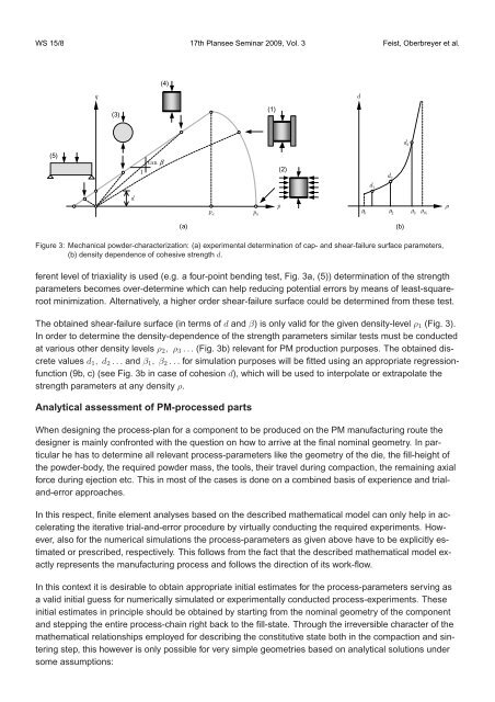
ferent level <strong>of</strong> triaxiality is used (e.g. a four-point bending test, Fig. 3a, (5)) determination <strong>of</strong> the strength<br />
parameters becomes over-determine which can help reducing potential errors by means <strong>of</strong> least-squareroot<br />
minimization. Alternatively, a higher order shear-failure surface could be determined from these test.<br />
¥<br />
p b<br />
(1)<br />
p<br />
(2)<br />
d<br />
d 2<br />
d 3<br />
d1 ¥0<br />
¥2<br />
¥3¥th<br />
(a) (b)<br />
Figure 3: Mechanical powder-characterization: (a) experimental determination <strong>of</strong> cap- and shear-failure surface parameters,<br />
(b) density dependence <strong>of</strong> cohesive strength d.<br />
The obtained shear-failure surface (in terms <strong>of</strong> d and β) is only valid for the given density-level ρ1 (Fig. 3).<br />
In order to determine the density-dependence <strong>of</strong> the strength parameters similar tests must be conducted<br />
at various other density levels ρ2, ρ3 . . . (Fig. 3b) relevant for PM production purposes. The obtained discrete<br />
values d1, d2 . . . and β1, β2 . . . for simulation purposes will be fitted using an appropriate regressionfunction<br />
(9b, c) (see Fig. 3b in case <strong>of</strong> cohesion d), which will be used to interpolate or extrapolate the<br />
strength parameters at any density ρ.<br />
Analytical assessment <strong>of</strong> PM-processed parts<br />
When designing the process-plan for a component to be produced on the PM manufacturing route the<br />
designer is mainly confronted with the question on how to arrive at the final nominal geometry. In particular<br />
he has to determine all relevant process-parameters like the geometry <strong>of</strong> the die, the fill-height <strong>of</strong><br />
the powder-body, the required powder mass, the tools, their travel during compaction, the remaining axial<br />
force during ejection etc. This in most <strong>of</strong> the cases is done on a combined basis <strong>of</strong> experience and trialand-error<br />
approaches.<br />
In this respect, finite element analyses based on the described mathematical model can only help in accelerating<br />
the iterative trial-and-error procedure by virtually conducting the required experiments. However,<br />
also for the numerical simulations the process-parameters as given above have to be explicitly estimated<br />
or prescribed, respectively. This follows from the fact that the described mathematical model exactly<br />
represents the manufacturing process and follows the direction <strong>of</strong> its work-flow.<br />
In this context it is desirable to obtain appropriate initial estimates for the process-parameters serving as<br />
a valid initial guess for numerically simulated or experimentally conducted process-experiments. These<br />
initial estimates in principle should be obtained by starting from the nominal geometry <strong>of</strong> the component<br />
and stepping the entire process-chain right back to the fill-state. Through the irreversible character <strong>of</strong> the<br />
mathematical relationships employed for describing the constitutive state both in the compaction and sintering<br />
step, this however is only possible for very simple geometries based on analytical solutions under<br />
some assumptions: