Near Net Shape Manufacturing of CuCr Vacuum Switching Contacts ...
Near Net Shape Manufacturing of CuCr Vacuum Switching Contacts ...
Near Net Shape Manufacturing of CuCr Vacuum Switching Contacts ...

You also want an ePaper? Increase the reach of your titles
YUMPU automatically turns print PDFs into web optimized ePapers that Google loves.
Feist, Oberbreyer et al. 17th Plansee Seminar 2009, Vol. 3 WS 15/11<br />
distribution it is decided to design both sunk-holes with identical diameter. In addition, for the analysis the<br />
geometry is simplified by neglecting all fillets except for the base-fillet <strong>of</strong> the slot-punches. The FE-model<br />
consisting <strong>of</strong> the fill body meshed with linear hexahedron elements and the tools modeled as rigid surfaces<br />
is depicted in Fig. 4b. The model reproduces the fill-body assuming it in a state after a first powdertransfer<br />
established by the inner punches forming the initial cavity <strong>of</strong> the upper sunk-hole (the powdertransfer<br />
itself could be numerically resolved only with a high numerical effort using adaptive procedures<br />
which is out <strong>of</strong> scope <strong>of</strong> the present work). A uniform fill-density ρf(x) = const is prescribed for the entire<br />
fill-body. Contact interactions are imposed between the surfaces <strong>of</strong> the powder-body and the tools. The<br />
upper edges <strong>of</strong> the dies are filleted or chamfered, respectively, in order to allow smooth ejection <strong>of</strong> the<br />
green-compact. All simulations are carried out using the commercial finite element code Abaqus [7].<br />
As a first step the inclined upper outer punch is brought into full contact with the powder leading to slightly<br />
higher densities at the outer perimeter <strong>of</strong> the part. Afterwards both outer punches are driven against each<br />
other ensuring most minimal effects related to friction against the die. Simultaneously, the inner punches<br />
move against one another, however, with a reduced height <strong>of</strong> travel, thus preventing powder-transfer between<br />
the inner and outer section and ensuring an almost uniform density-distribution. After full compaction<br />
the upper punches are slightly released before the part is ejected and the punches are finally removed.<br />
The model now represents the state <strong>of</strong> the unloaded green-compact and the initial state <strong>of</strong> the sinteringprocess<br />
as shown in Fig. 5a. The latter can then be simulated employing the deformed mesh associated<br />
to the end <strong>of</strong> the compaction-simulation. Besides, the green-density distribution ρg(x) serves as additional<br />
input to the sintering-simulation. For the sintering-simulation only appropriate statically determine<br />
and constraint-free support-conditions have to be provided, however, no additional parts or tools have to<br />
be considered.<br />
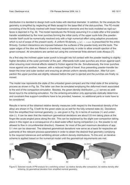
Results in terms <strong>of</strong> the obtained relative density measures (with respect to the theoretical density <strong>of</strong> the<br />
alloy) are shown in Fig. 5 both for the green-state (a) as well for the fully sintered state (b). Deviations<br />
from the simplified final nominal geometry ∆n are given in Fig. 5c in terms <strong>of</strong> oversize (+) and undersize<br />
(-). It can be seen that the maximum geometrical deviations are about 0.8 mm taking place at the<br />
finger-like acute-angled piece along the slot. This can be explained by the slight over-compaction taking<br />
place in this region as a consequence <strong>of</strong> a dead-water-effect during compaction (i.e. the powder is not<br />
allowed to flow in circumferential direction). However, for most <strong>of</strong> the part maximum deviations <strong>of</strong> app.<br />
0.1 mm can be observed. The obtained geometrical deviations now serve as a basis for respective adjustments<br />
<strong>of</strong> the relevant process-parameters in order to obtain the desired final geometry complying<br />
to the required tolerances and exhibiting almost uniform density-distributions. To this end, an iterative<br />
scheme is applied based on the numerical model until the geometrical requirements are met.<br />
d g [-] d s [-] ¦n [mm]<br />
1.0<br />
0.8<br />
(a)<br />
1.0<br />
0.9<br />
+0.8<br />
-0.2<br />
(b) (c)<br />
Figure 5: Selected results <strong>of</strong> PM analysis for a switching contact: (a) relative density after compaction, (b) relative density after<br />
sintering, (b) geometrical deviation from simplified nominal geometry.