TECHNICAL REPORT 92-14 - Nagra
TECHNICAL REPORT 92-14 - Nagra
TECHNICAL REPORT 92-14 - Nagra

Create successful ePaper yourself
Turn your PDF publications into a flip-book with our unique Google optimized e-Paper software.
NAGRA NTB <strong>92</strong>-<strong>14</strong> - 7 -<br />
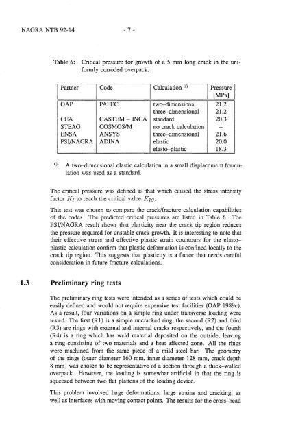
Table 6: Critical pressure for growth of a 5 mm long crack in the uniformly<br />
corroded overpack.<br />
I Partner<br />
OAP PAFEC<br />
CEA CASTEM - INCA<br />
STEAG COSMOS/M<br />
ENSA ANSYS<br />
PSI/NAGRA ADINA<br />
I Calculation 1)<br />
two-dimensional<br />
three-dimensional<br />
standard<br />
no crack calculation<br />
three-dimensional<br />
elastic<br />
elasto-plastic<br />
Pressure I<br />
I [MPa]<br />
21.2<br />
21.2<br />
20.3<br />
-<br />
21.6<br />
20.0<br />
18.3<br />
1): A two-dimensional elastic calculation in a small displacement formulation<br />
was used as a standard.<br />
The critical pressure was defined as that which caused the stress intensity<br />
factor !{I to reach the critical value !{IC.<br />
This test was chosen to compare the crack/fracture calculation capabilities<br />
of the codes. The predicted critical pressures are listed in Table 6. The<br />
PSI/NAGRA result shows that plasticity near the crack tip region reduces<br />
the pressure required for unstable crack growth. It is interesting to note that<br />
their effective stress and effective plastic strain countours for the elastoplastic<br />
calculation confirm that plastic deformation is confined locally to the<br />
crack tip region. This suggests that plasticity is a factor that needs careful<br />
consideration in future fracture calculations.<br />
1.3 Preliminary ring tests<br />
The preliminary ring tests were intended as a series of tests which could be<br />
easily defined and would not require expensive test facilities (OAP 1989c).<br />
As a result, four variations on a simple ring under transverse loading were<br />
tested. The first (Rl) is a simple uncracked ring, the second (R2) and third<br />
(R3) are rings with external and internal cracks respectively, and the fourth<br />
(R4) is a ring which has weld material deposited on the outside, leaving<br />
a ring consisting of two materials and a heat affected zone. All the rings<br />
were machined from the same piece of a mild steel bar. The geometry<br />
of the rings (outer diameter 160 mm, inner diameter 128 mm, crack depth<br />
8 mm) was chosen to be representative of a section through a thick-walled<br />
overpack. However, the loading is somewhat artificial in that the ring is<br />
squeezed between two fiat plattens of the loading device.<br />
This problem involved large deformations, large strains and cracking, as<br />
well as interfaces with moving contact points. The results for the cross-head