TECHNICAL REPORT 92-14 - Nagra
TECHNICAL REPORT 92-14 - Nagra
TECHNICAL REPORT 92-14 - Nagra

Create successful ePaper yourself
Turn your PDF publications into a flip-book with our unique Google optimized e-Paper software.
NAGRA NTB <strong>92</strong>-<strong>14</strong> - 13 -<br />
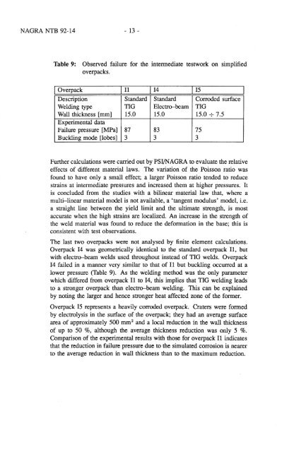
Table 9: Observed failure for the intermediate testwork on simplified<br />
overpacks.<br />
I Overpack I II 1<strong>14</strong> I IS<br />
Description Standard Standard Corroded surface<br />
Welding type TIG Electro-beam TIG<br />
Wall thickness [mm] IS.0 IS.0 IS.0 -7- 7.S<br />
Experimental data<br />
Failure pressure [MPa] 87 83 7S<br />
Buckling mode [lobes] 3 3 3<br />
Further calculations were carried out by PSI/NAGRA to evaluate the relative<br />
effects of different material laws. The variation of the Poisson ratio was<br />
found to have only a small effect; a larger Poisson ratio tended to reduce<br />
strains at intermediate pressures and increased them at higher pressures. It<br />
is concluded from the studies with a bilinear material law that, where a<br />
multi-linear material model is not available, a 'tangent modulus' model, i.e.<br />
a straight line between the yield limit and the ultimate strength, is most<br />
accurate when the high strains are localized An increase in the strength of<br />
the weld material was found to reduce the deformation in the base; this is<br />
consistent with test observations.<br />
The last two overpacks were not analysed by finite element calculations.<br />
Overpack <strong>14</strong> was geometrically identical to the standard overpack II, but<br />
with electro-beam welds used throughout instead of TIG welds. Overpack<br />
<strong>14</strong> failed in a manner very similar to that of II but buckling occurred at a<br />
lower pressure (Table 9). As the welding method was the only parameter<br />
which differed from overpack II to <strong>14</strong>, this implies that TIG welding leads<br />
to a stronger overpack than electro-beam welding. This can be explained<br />
by noting the larger and hence stronger heat affected zone of the former.<br />
Overpack IS represents a heavily corroded overpack. Craters were formed<br />
by electrolysis in the surface of the overpack; they had an average surface<br />
area of approximately SOO mm 2 and a local reduction in the wall thickness<br />
of up to SO %, although the average thickness reduction was only S %.<br />
Comparison of the experimental results with those for overpack II indicates<br />
that the reduction in failure pressure due to the simulated corrosion is nearer<br />
to the average reduction in wall thickness than to the maximum reduction.