PG-C45X - diagramas.diagram...
PG-C45X - diagramas.diagram...
PG-C45X - diagramas.diagram...

Create successful ePaper yourself
Turn your PDF publications into a flip-book with our unique Google optimized e-Paper software.
<strong>PG</strong>-<strong>C45X</strong><br />
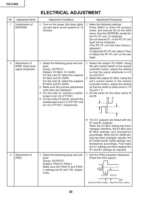
ELECTRICAL ADJUSTMENT<br />
No. Adjustment Items Adjustment Conditions Adjustment Procedures<br />
1 Initialization of<br />
EEPROM<br />
2 Adjustment of<br />
RGB1 black level<br />
signal amplitude<br />
3 Adjustment of<br />
PSIG<br />
1. Turn on the power (the lamp lights<br />
up) and warm up the system for 15<br />
minutes.<br />
1. Select the following group and subjects.<br />
Group: OUTPUT1<br />
Subject: G1-BLK, G1-GAIN<br />
For the color R, select the subjects<br />
R1-BLK and R1-GAIN.<br />
For the color B, select the subjects<br />
B1-BLK and B1-GAIN.<br />
2. Make sure the process adjustment<br />
color bars are displayed.<br />
3. For the color G, connect a oscilloscope<br />
to pin (2) of P1301.<br />
4. For the colors R and B, connect the<br />
oscilloscope to pin (1) of P1301 and<br />
pin (3) of P1301, respectively.<br />
1. Select the following group and subjects.<br />
Group: OUTPUT2<br />
Subject: PSIG-H, PSIG-L<br />
Make sure the PSIG-H and PSIG-<br />
L settings are 64 and 100, respectively.<br />
20<br />
1. Make the following settings.<br />
Press S2601 to enter the process<br />
mode, and execute S2 on the SSS<br />
menu. Now the EEPROM, except for<br />
the PC I/F unit, is initialized.<br />
Do not execute S1, or the PC I/F unit<br />
itself will be initialized.<br />
(The PC I/F unit has been factoryadjusted.)<br />
To adjust the PC I/F unit, refer to "How<br />
to Adjust the PC I/F unit" on the last<br />
page.<br />
1. Select the subject G1-GAIN. Using<br />
the set's control switch or the remote<br />
controller button, adjust the setting<br />
so that the signal amplitude is 4.0<br />
Vp-p±0.05 V.<br />
2. Select the subject G1-BLK. Using the<br />
set's control switch or the remote<br />
controller button, adjust the setting<br />
so that the white-to-white level is 1.8<br />
Vp-p±0.1 V.<br />
3. Do the same for the other colors R<br />
and B.<br />
~ The G1 subjects are linked with the<br />
R1 and B1 subjects.<br />
When the G1-BLK setting has been<br />
changed, therefore, the R1-BLK and<br />
B1-BLK settings vary themselves<br />
accordingly. When the G1-GAIN setting<br />
has been changed, equally, the<br />
R1-GAIN and B1-GAIN settings vary<br />
themselves accordingly. First make<br />
the G1 settings and then readjust the<br />
R1 and B1 settings as required.<br />
1. Get the PSIG waveform displayed.<br />
(Feed the XGA signal.)<br />
PSIG<br />
2.5V DC 5.6V DC<br />
GND<br />
Adjust the PSIG-H setting. Adjust the PSIG-L setting.