1 Code Generation Code generator phase ... - VTU e-Learning
1 Code Generation Code generator phase ... - VTU e-Learning
1 Code Generation Code generator phase ... - VTU e-Learning

You also want an ePaper? Increase the reach of your titles
YUMPU automatically turns print PDFs into web optimized ePapers that Google loves.
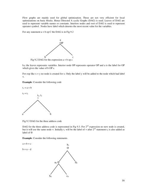
Flow graphs are mainly used for global optimization. These are not very efficient for local<br />
optimizations on basic blocks. Hence Directed A cyclic Graphs (DAG) is used. Leaves of DAG are<br />
used to represent variable names or constants. Interiors nodes and root of DAG is used to represent<br />
operator symbol. Nodes have label which denotes the most recent value for the variables.<br />
For any statement a = b op C the DAG is in Fig 9.2<br />
b c<br />
Fig 9.2 DAG for the expression a = b op c<br />
b,c the leaves represents variables. Interior node OP represents operator OP and a is the label for OP<br />
which gives the value of b OP c.<br />
For exp like x = y no node is created for x. Only the label y will be added to the node which had label<br />
x.<br />
Example: Consider the following code<br />
t1 = a + b<br />
t2 = t1<br />
Fig 9.3 DAG for the three address code<br />
DAG for the three address code is represented in Fig 9.3. For 2 nd expression no new node is created,<br />
but it will use the same node +. Initially t1 will be the label of + after 2 nd statement t2 is also added as<br />
label of ⊕<br />
Example: Consider the following statements<br />
a = b + c<br />
b = a – d<br />
t2, t1<br />
*<br />
a b<br />
a<br />
OP<br />
b1<br />
Ө<br />
a0 ⊕ d0<br />
b0 c0<br />
16