BC140 BC141
BC140 BC141
BC140 BC141

Create successful ePaper yourself
Turn your PDF publications into a flip-book with our unique Google optimized e-Paper software.
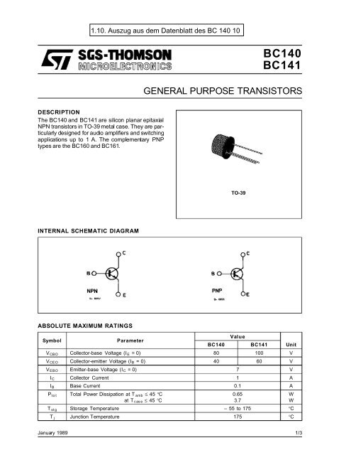
DESCRIPTION<br />
The <strong>BC140</strong> and <strong>BC141</strong> are silicon planar epitaxial<br />
NPN transistors in TO-39 metal case. They are particularly<br />
designed for audio amplifiers and switching<br />
applications up to 1 A. The complementary PNP<br />
types are the BC160 and BC161.<br />
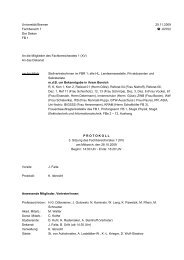
INTERNAL SCHEMATIC DIAGRAM<br />
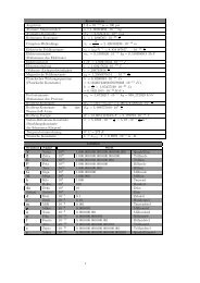
ABSOLUTE MAXIMUM RATINGS<br />
January 1989<br />
<strong>BC140</strong><br />
<strong>BC141</strong><br />
GENERAL PURPOSE TRANSISTORS<br />
TO-39<br />
Symbol Parameter<br />
<strong>BC140</strong><br />
Value<br />
<strong>BC141</strong> Unit<br />
VCBO Collector-base Voltage (I E =0) 80 100 V<br />
VCEO Collector-emitter Voltage (IB =0) 40 60 V<br />
VEBO Emitter-base Voltage (I C =0) 7 V<br />
IC Collector Current 1 A<br />
I B Base Current 0.1 A<br />
Ptot Total Power Dissipation at T amb ≤ 45 °C<br />
0.65<br />
W<br />
at T case ≤ 45 °C<br />
3.7<br />
W<br />
T stg Storage Temperature – 55 to 175 °C<br />
T j Junction Temperature 175 °C<br />
1/3
<strong>BC140</strong>-<strong>BC141</strong><br />
THERMAL DATA<br />
ELECTRICAL CHARACTERISTICS (T amb =25°C unless otherwise specified)<br />
Symbol Parameter Test Conditions Min. Typ. Max. Unit<br />
ICES Collector Cutoff Current<br />
(IE =0)<br />
V(BR)CBO Collector-base Breakdown<br />
Voltage<br />
(IE =0)<br />
V(BR)CEO* Collector-emitter<br />
Breakdown Voltage<br />
(IB =0)<br />
V(BR)EBO Emitter-base<br />
Breakdown Voltage<br />
(IC =0)<br />
VCE(sat)* Collector-emitter<br />
Saturation Voltage<br />
VCES =60 V<br />
VCES =60 V Tamb = 150 °C<br />
IC =100μA<br />
IC =30mA<br />
for <strong>BC140</strong><br />
for <strong>BC141</strong><br />
for <strong>BC140</strong><br />
for <strong>BC141</strong><br />
80<br />
100<br />
40<br />
60<br />
100<br />
100<br />
IE =100μA 7 V<br />
I C =100mA<br />
IC =500mA<br />
IC =1A<br />
IC =100mA<br />
IC =1A<br />
IB =10 mA<br />
IB =50 mA<br />
IB = 0.1 A<br />
0.1<br />
0.35<br />
0.6 1<br />
VBE* Base-emitter Voltage I C =1A VCE = 1 V 1.25 1.8 V<br />
h FE* DC Current Gain I C =100μA VCE =1V<br />
for <strong>BC140</strong>-141<br />
75<br />
for <strong>BC140</strong>-141 Gr. 6<br />
28<br />
for <strong>BC140</strong>-141 Gr. 10<br />
40<br />
for <strong>BC140</strong>-141 Gr. 16<br />
90<br />
VCE =1V<br />
for <strong>BC140</strong>-141<br />
for <strong>BC140</strong>-141 Gr. 6<br />
for <strong>BC140</strong>-141 Gr.10<br />
for <strong>BC140</strong>-141 Gr.16<br />
VCE =1V<br />
for <strong>BC140</strong>-141<br />
for <strong>BC140</strong>-141 Gr. 6<br />
for <strong>BC140</strong>-141 Gr.10<br />
for <strong>BC140</strong>-141 Gr.16<br />
fT Transition Frequency I C =50mA VCE = 10 V 50 MHz<br />
C CBO<br />
Collector-base<br />
Capacitance<br />
I E =0<br />
f=1MHz<br />
VCB =10V<br />
12 25 pF<br />
t on Turn-on Time I C =100mA<br />
IB1 = 5 mA 250 ns<br />
t off Turn-off Time I C =100mA<br />
IB1 =IB2 = 5 mA 850 ns<br />
* Pused : pulse duration = 300 μs, duty cycle = 1 %.<br />
2/3<br />
Rth j-case<br />
Rth j-amb<br />
Thermal Resistance Junction-case<br />
Thermal Resistance Junction-ambient<br />
Max<br />
Max<br />
40<br />
40<br />
63<br />
100<br />
140<br />
63<br />
100<br />
160<br />
26<br />
15<br />
20<br />
30<br />
35<br />
200<br />
250<br />
100<br />
160<br />
250<br />
°C/W<br />
°C/W<br />
nA<br />
μA<br />
V<br />
V<br />
V<br />
V<br />
V<br />
V<br />
V
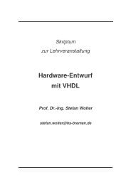
Collector-emitter Saturation Voltage. Base-emitter Voltage.<br />
DC Curent Gain. Transiition Frequency.<br />
<strong>BC140</strong>-<strong>BC141</strong><br />
3/3
<strong>BC140</strong>-<strong>BC141</strong><br />
4/3<br />
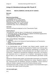
DIM.<br />
mm inch<br />
MIN. TYP. MAX. MIN. TYP. MAX.<br />
A 12.7 0.500<br />
B 0.49 0.019<br />
D 6.6 0.260<br />
E 8.5 0.334<br />
F 9.4 0.370<br />
G 5.08 0.200<br />
H 1.2 0.047<br />
I 0.9 0.035<br />
L 45 o (typ.)<br />
H<br />
I<br />
G<br />
TO39 MECHANICAL DATA<br />
L<br />
F<br />
E<br />
D A<br />
B<br />
P008B
Information furnished is believed to be accurate and reliable. However, SGS-THOMSON Microelectronics assumes no responsability for the<br />
consequences of use of such information nor for any infringement of patents or other rights of third parties which may results from its use. No<br />
license is granted by implication or otherwise under any patent or patent rights of SGS-THOMSON Microelectronics. Specificationsmentioned<br />
in this publication are subject to change without notice. This publication supersedes and replaces all information previously supplied.<br />
SGS-THOMSON Microelectronicsproducts are not authorized for use as critical components in life supportdevices or systems without express<br />
written approval of SGS-THOMSON Microelectonics.<br />
© 1994 SGS-THOMSON Microelectronics - All Rights Reserved<br />
<strong>BC140</strong>-<strong>BC141</strong><br />
SGS-THOMSON Microelectronics GROUP OF COMPANIES<br />
Australia - Brazil - France - Germany - Hong Kong - Italy - Japan - Korea - Malaysia - Malta - Morocco - The Netherlands -<br />
Singapore - Spain - Sweden - Switzerland - Taiwan - Thailand - United Kingdom - U.S.A<br />
5/3