Butterfly valve JHP - Fluid Control Services
Butterfly valve JHP - Fluid Control Services
Butterfly valve JHP - Fluid Control Services

You also want an ePaper? Increase the reach of your titles
YUMPU automatically turns print PDFs into web optimized ePapers that Google loves.
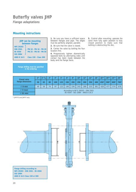
<strong>Butterfly</strong> <strong>valve</strong>s <strong>JHP</strong><br />
Flange adaptations<br />
Mounting instructions<br />
<strong>JHP</strong> can be mounting<br />
between flanges<br />
NFE 29203<br />
}<br />
DIN 2501 PN 10 - PN 16 - PN 20<br />
BS 4504 PN 25 - PN 40 - PN 50<br />
ISO 2084<br />
ANSI B 16-5 Class 150 - Class 300<br />
Flange drilling according to:<br />
NFE 29203 - DIN 2501 - BS 4504<br />
ISO 2084<br />
ANSI B 16.5 Class 150 et 300<br />
20<br />
Flange drilling must be specified<br />
in the ordering<br />
Closed <strong>valve</strong><br />
flange dimensions<br />
1. Be sure you have a sufficient space<br />
between flanges and pipe. The edges<br />
must be perfectly aligned, parallel.<br />
2. Be sure that the <strong>valve</strong> is closed.<br />
3. Center the <strong>valve</strong> by bolting the four<br />
locators first.<br />
4. Progressively tighten diametrically<br />
opposed bolts by alternating sides until<br />
contact has been made between the<br />
body and the flange faces.<br />
5. <strong>Control</strong> after mounting: operate the<br />
<strong>valve</strong> from fully open position to fully<br />
closed position to make sure that<br />
nothing is obstructing the disc.<br />
2” 2“ 1 / 2 3” 4” 5” 6” 8” 10” 12” 14” 16” 18”* 20”* 24”* 28”*<br />
50 65 80 100 125 150 200 250 300 350 400 450* 500* 600* 700*<br />
∅ D mini 49 59 74 97 122 146 194 243 289 333 381 428 477 574 676<br />
∅ D maxi<br />
According to NF E 29203 - DIN 2501<br />
∅ D1 mini<br />
BS 4504 - ISO 2084 - ANSI B 16.5<br />
* <strong>JHP</strong>-FS and <strong>JHP</strong>-P only.<br />
∅ D1<br />
∅ D