The stability of the excavation face of shallow civil and mining tunnels
The stability of the excavation face of shallow civil and mining tunnels
The stability of the excavation face of shallow civil and mining tunnels

Create successful ePaper yourself
Turn your PDF publications into a flip-book with our unique Google optimized e-Paper software.
P. ORESTE: THE STABILITY OF THE EXCAVATION FACE OF SHALLOW CIVIL AND MINING TUNNELS<br />
This hypo<strong>the</strong>sis makes it possible to limit <strong>the</strong> verification<br />
<strong>of</strong> <strong>the</strong> behaviour <strong>of</strong> <strong>the</strong> reinforcement elements to <strong>the</strong><br />
following three inequalities:<br />
S<br />
£ sadm<br />
⋅ Abar<br />
(9)<br />
n<br />
S<br />
£ tadm ⋅( p⋅fhole ⋅ La<br />
) (10)<br />
n<br />
S<br />
£ tadm ⋅( p⋅fhole ⋅ Lp<br />
) (11)<br />
n<br />
where:<br />
σ adm: <strong>the</strong> maximum allowed traction stress in <strong>the</strong><br />
fibreglass;<br />
τ adm: <strong>the</strong> maximum allowed shear stress at <strong>the</strong><br />
mortar-ground inter<strong>face</strong>;<br />
Φ hole: <strong>the</strong> diameter <strong>of</strong> <strong>the</strong> hole;<br />
L a: <strong>the</strong> length <strong>of</strong> <strong>the</strong> dowel in prismatic block 1;<br />
L p: <strong>the</strong> length <strong>of</strong> <strong>the</strong> dowel in <strong>the</strong> stable portion <strong>of</strong><br />
<strong>the</strong> ground;<br />
n: <strong>the</strong> number <strong>of</strong> dowels foreseen at <strong>the</strong> <strong>excavation</strong><br />
<strong>face</strong>;<br />
A bar: section area <strong>of</strong> each single element.<br />
It is possible to define A bar , L a , L p <strong>and</strong> n from equations<br />
9-11, though not in a univocal manner.<br />
5 DETAILED ANALYSIS OF THE<br />
GROUND-DOWEL INTERACTION<br />
In order to perform an accurate analysis <strong>of</strong> <strong>the</strong> grounddowels<br />
interaction, a new analytical formulation is<br />
presented in <strong>the</strong> following; it is able to provide a reasonable<br />
evaluation <strong>of</strong> <strong>the</strong> behaviour <strong>of</strong> a single dowel <strong>and</strong> it<br />
also allows a quick dimensioning <strong>of</strong> <strong>the</strong> reinforcement<br />
system.<br />
<strong>The</strong> unknown factors are <strong>the</strong> global forces (axial N, shear<br />
T <strong>and</strong> bending M stresses) that develop along <strong>the</strong> dowels<br />
<strong>and</strong> which are functions <strong>of</strong> a small dislocation displacement<br />
<strong>of</strong> <strong>the</strong> potentially unstable block.<br />
<strong>The</strong> design <strong>of</strong> <strong>the</strong> dowels can take place through a<br />
sequence <strong>of</strong> trials, assuming different reinforcement<br />
schemes, until <strong>the</strong> safety factor <strong>of</strong> <strong>the</strong> potentially<br />
unstable block at <strong>the</strong> <strong>excavation</strong> <strong>face</strong> is higher than <strong>the</strong><br />
minimum allowed value.<br />
After having defined <strong>the</strong> safety factor <strong>of</strong> <strong>the</strong> <strong>excavation</strong><br />
<strong>face</strong> in its natural state (i.e., without reinforcement),<br />
according to <strong>the</strong> criteria reported in section 2, <strong>and</strong><br />
having verified <strong>the</strong> needs <strong>of</strong> reinforcement to increase<br />
<strong>the</strong> safety factor, <strong>the</strong> main stages <strong>of</strong> <strong>the</strong> design can be<br />
summarised as follows:<br />
62. ACTA GEOTECHNICA SLOVENICA, 2011/2<br />
a) definition <strong>of</strong> <strong>the</strong> chosen reinforcement scheme<br />
(number, position <strong>and</strong> dimensions <strong>of</strong> <strong>the</strong> dowels);<br />
b) assignment <strong>of</strong> a value to <strong>the</strong> angle ϑ;<br />
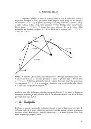
c) assignment <strong>of</strong> an arbitrary displacement δ to unstable<br />
block 1 along <strong>the</strong> sliding direction; evaluation <strong>of</strong> <strong>the</strong><br />
components <strong>of</strong> such a displacement-vector acting in<br />
<strong>the</strong> normal δ t <strong>and</strong> axial δ n dowel directions (Figure 5);<br />
d) based on δ t <strong>and</strong> δ n , evaluation <strong>of</strong> <strong>the</strong> shear force T, <strong>of</strong><br />
<strong>the</strong> bending moment M, <strong>of</strong> <strong>the</strong> axial tensile force N<br />
<strong>and</strong> <strong>of</strong> <strong>the</strong> relative dowel-rock displacement v r, induced<br />
along each dowel. In order to design <strong>the</strong> dowels<br />
<strong>and</strong> analyse <strong>the</strong> <strong>stability</strong> <strong>of</strong> <strong>the</strong> <strong>face</strong>, <strong>the</strong> values <strong>of</strong> T,<br />
N <strong>and</strong> M at <strong>the</strong> sliding sur<strong>face</strong> (plan 2) (where <strong>the</strong><br />
maximum values <strong>of</strong> <strong>the</strong> shear force <strong>and</strong> <strong>the</strong> traction<br />
axial force develop) are <strong>of</strong> particular importance;<br />
e) calculation <strong>of</strong> <strong>the</strong> “local” safety factors for failure<br />
<strong>of</strong> <strong>the</strong> bar <strong>and</strong> <strong>of</strong> <strong>the</strong> dowel-ground connection, for<br />
each dowel, on <strong>the</strong> basis <strong>of</strong> <strong>the</strong> values <strong>of</strong> T, N <strong>and</strong> M<br />
<strong>and</strong> <strong>of</strong> <strong>the</strong> displacements v r evaluated in d);<br />
f) evaluation <strong>of</strong> <strong>the</strong> ratio η between each calculated<br />
local safety factor <strong>and</strong> <strong>the</strong> corresponding previously<br />
imposed minimum allowable value;<br />
g) <strong>the</strong> minimum value <strong>of</strong> η for each local safety factor<br />
<strong>and</strong> each dowel at <strong>the</strong> <strong>face</strong>, multiplied by <strong>the</strong> arbitrary<br />
displacement δ applied to <strong>the</strong> block, represents<br />
<strong>the</strong> maximum displacement δ max that <strong>the</strong> unstable<br />
block can sustain before at least one <strong>of</strong> <strong>the</strong> local safety<br />
factors drops below its minimum allowable value;<br />
h) evaluation <strong>of</strong> <strong>the</strong> N <strong>and</strong> T forces in each single dowel<br />
at <strong>the</strong> sliding sur<strong>face</strong>, for a displacement <strong>of</strong> <strong>the</strong> block<br />
equal to δ max ; such forces represent <strong>the</strong> maximum<br />
contribution that each dowel can <strong>of</strong>fer to <strong>the</strong> <strong>stability</strong><br />
<strong>of</strong> <strong>the</strong> block;<br />
i) determination <strong>of</strong> <strong>the</strong> “global” safety factor <strong>of</strong> <strong>the</strong><br />
unstable block 1, considering <strong>the</strong> contribution <strong>of</strong> <strong>the</strong><br />
dowels, for <strong>the</strong> assigned value <strong>of</strong> ϑ;<br />
j) repetition <strong>of</strong> steps b)-i), increasing <strong>the</strong> value <strong>of</strong> ϑ at<br />
each cycle until ϑ =90°; <strong>the</strong> “global” safety factor <strong>of</strong><br />
<strong>the</strong> unstable block is obtained at each cycle for <strong>the</strong><br />
assigned value <strong>of</strong> ϑ;<br />
k) <strong>the</strong> minimum value <strong>of</strong> <strong>the</strong> obtained global safety<br />
factors is <strong>the</strong>n considered as <strong>the</strong> safety factor <strong>of</strong> <strong>the</strong><br />
reinforced <strong>excavation</strong> <strong>face</strong>; if this value is lower or<br />
much higher than <strong>the</strong> minimum allowable value,<br />
return to point a), change <strong>the</strong> reinforcement scheme<br />
<strong>and</strong> repeat <strong>the</strong> whole procedure until <strong>the</strong> reinforcement<br />
scheme that is suitable for stabilising <strong>the</strong> <strong>face</strong> is<br />
obtained.<br />
<strong>The</strong> detail <strong>of</strong> <strong>the</strong> proposed ma<strong>the</strong>matical procedure is<br />
developed in Oreste [4]. <strong>The</strong> global safety factor F s,ϑ <strong>of</strong><br />
<strong>the</strong> unstable block 1 must now be evaluated, taking into<br />
consideration <strong>the</strong> stabilising forces produced by each<br />
dowel (i=1÷n)