PermitPackage - Vernon High School.pdf - Florida Solar Energy ...
PermitPackage - Vernon High School.pdf - Florida Solar Energy ...
PermitPackage - Vernon High School.pdf - Florida Solar Energy ...

You also want an ePaper? Increase the reach of your titles
YUMPU automatically turns print PDFs into web optimized ePapers that Google loves.
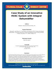
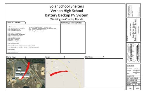
<strong>Solar</strong> <strong>School</strong> Shelters<br />
<strong>Vernon</strong> <strong>High</strong> <strong>School</strong><br />
Battery Backup PV System<br />
Washington County, <strong>Florida</strong><br />
Table of Content: Permitting/Planning Notes:<br />
A-00 Cover Sheet<br />
A-01 Symbols & System Description<br />
A-02 Equipment Location<br />
A-03 System Riser Diagram<br />
E-01 Module Wiring Layout<br />
E-02 Inverter/Charger Wiring Detail<br />
E-03 Inverter/AC Wiring Detail<br />
E-04 Battery Wiring Detail<br />
E-05 Electrical Calculation<br />
E-06 Labels & Markings<br />
E-07-08 Monitoring System<br />
N-01 Installation Notes<br />
M-01 <strong>Solar</strong> Equipment Enclosure Location vs Array Detail<br />
M-02 <strong>Solar</strong> Equipment Enclosure - <strong>School</strong> Wall Connections Detail<br />
P-01 PVWatts<br />
DS-01:04 Data Sheet<br />
Aerial View:<br />
A01 of 07 through A07 of 07 Enclosure Detail<br />
S-1 Foundation Plan, Framing plan and Structural Notes<br />
S-2 Section and Attachment Detail<br />
S-3 Clamp Placement Layout<br />
Map:<br />
Site View:<br />
3232 Moss Hill Road, <strong>Vernon</strong>, FL 32462<br />
Design for:<br />
I CERTIFY THAT THIS PV<br />
SYSTEM FULLY COMPLIES<br />
WITH THE REQUIREMENTS<br />
OF NEC 690.<br />
PV SYSTEM<br />
Total Output:<br />
# Modules:<br />
Manufacturer:<br />
Model:<br />
<strong>Vernon</strong> <strong>High</strong> <strong>School</strong><br />
<strong>Solar</strong> <strong>School</strong> Shelters<br />
Battery Backup PV System<br />
Cover Sheet<br />
SCALE: NTS<br />
DRAWN BY: RB,HB<br />
CHECKED BY: EC<br />
DATE: 10/03/11<br />
SHEET 1 OF 20<br />
Revision:<br />
00<br />
10.08 kW<br />
42<br />
<strong>Solar</strong> World<br />
240<br />
Sheet:<br />
E.E. Castillo, PE<br />
Licensed Engineer #: PE52590<br />
Certification of Authorization #28406<br />
3601 N. DIXIE HWY, BAY 16 BOCA RATON, FL 33431<br />
PHONE: 561.750.8677 FAX:561.750.0518<br />
A-00
Symbols: Abbreviations:<br />
Section..............<br />
Elevation ...........<br />
Detail ................<br />
Detail ................<br />
(Enlarged Plan)<br />
Keyed Notes ..........<br />
Ground Terminal .....<br />
Grounding Point/rod....<br />
<strong>Solar</strong> Panel ......... or<br />
Combiner Box ..........<br />
DC Disconnect ..........<br />
Main Distribution<br />
Panel ......................<br />
Fuse ......................<br />
Overcurrent Breaker ..<br />
Inverter ....................<br />
Transformer .............<br />
Automatic ...............<br />
Transfer Switch<br />
X<br />
X-XX<br />
X<br />
X-XX<br />
X<br />
X-XX<br />
X<br />
X-XX<br />
1<br />
CB<br />
DCD<br />
MDP<br />
ATS<br />
Sheet where<br />
section is located<br />
Detail ID Letter<br />
Sheet where<br />
section is located<br />
Detail ID Letter<br />
Sheet where<br />
section is located<br />
Detail ID Letter<br />
Area to be enlarged<br />
Sheet where<br />
section is located<br />
Keyed note designation<br />
on applicable sheet<br />
00 Module with Source<br />
Circuit number<br />
AC Alternating Current<br />
APPROX Approximate<br />
AWG American Wire Gauge<br />
CB Combiner Box<br />
DC Direct Current<br />
DCD Direct Current Disconnect<br />
DISC Disconnect<br />
(E) Existing<br />
EL Elevation<br />
EQ Equal<br />
JB Junction Box<br />
MCB Main Combiner Box<br />
MFR Manufacturer<br />
MIN Minimum<br />
MISC Miscellaneous<br />
(N) New<br />
OCPD OverCurrent Protection Device<br />
POCC Point Of Common Coupling<br />
PV Photovoltaic<br />
SF Squarefoot/feet<br />
STC Standard Test Conditions<br />
TBD To Be Determined<br />
TYP Typical<br />
VIF Verify In Field<br />
WP Weather Proof<br />
System Description<br />
This system is a grid-tie, PV system with battery back up, with PV generation consisting of 42 <strong>Solar</strong> World<br />
SW-240 modules with a combined STC rated dc output power of 10,080 watts. The modules are<br />
connected into two groups of five 3-module source circuits and one group of four 3-module source<br />
circuits that feed three Outback FM80 charge controllers. The charge controllers feed the system batteries<br />
and the inverters, which are connected to supply 120/208 volt ac (uninterruptable) to the standby loads<br />
and also to the electric utility grid. The system is provided with all disconnects and labels required by the<br />
National Electrical Code. The system batteries are sized for 610 amp hours at 48V providing approximately<br />
27.0 kWh to standby (uninterruptible) loads.<br />
PV<br />
Array<br />
Charge<br />
Controller<br />
Batteries<br />
Inverter<br />
Uninterruptible<br />
Standby<br />
Loads<br />
Figure 1: PV System block Diagram showing main system components<br />
Main<br />
Distribution<br />
Panel<br />
Interruptible<br />
Loads<br />
When the sun is shining, power from the PV array is used to keep the batteries fully charged. After<br />
charging the batteries, the PV power is made available to the standby loads. If the PV power meets the<br />
requirements of the standby loads, any remaining PV power is then directed to the interruptible loads of<br />
the occupancy. If any PV power remains after the interruptible loads have been powered, it is delivered to<br />
the utility. When utility power is available, but PV power is not available, standby loads are supplied by<br />
the utility. If neither utility nor PV power is available, standby loads are supplied by the batteries. Thus,<br />
the batteries are only cycled if utility power is lost. The batteries used are specially designed, deep cycle,<br />
maintenance free batteries that are capable of undergoing approximately 3,000-4,000 charge-discharge<br />
cycles. Designing the system to minimize battery cycling extends the life of the batteries.<br />
The inverter meets the requirements of IEEE 1547 and UL 1741. This means that if it detects a loss<br />
of utility power, it will automatically disconnect from the utility. When this happens, only the<br />
uninterruptible loads are powered by the inverter. When utility voltage is restored, the inverter<br />
automatically reconnects to the utility grid after verifying the utility voltage and frequency stability.<br />
On a average day of <strong>Florida</strong> sunshine, the system will produce approximately 36.5kWh of clean<br />
energy.<br />
3232 Moss Hill Road, <strong>Vernon</strong>, FL 32462<br />
Design for:<br />
I CERTIFY THAT THIS PV<br />
SYSTEM FULLY COMPLIES<br />
WITH THE REQUIREMENTS<br />
OF NEC 690.<br />
PV SYSTEM<br />
Total Output:<br />
# Modules:<br />
Manufacturer:<br />
Model:<br />
<strong>Vernon</strong> <strong>High</strong> <strong>School</strong><br />
<strong>Solar</strong> <strong>School</strong> Shelters<br />
Battery Backup PV System<br />
Symbols and System Description<br />
SCALE: NTS<br />
DRAWN BY: RB,HB<br />
CHECKED BY: EC<br />
DATE: 10/03/11<br />
SHEET 2 OF 20<br />
Revision:<br />
00<br />
10.08 kW<br />
42<br />
<strong>Solar</strong> World<br />
240<br />
Sheet:<br />
E.E. Castillo, PE<br />
Licensed Engineer #: PE52590<br />
Certification of Authorization #28406<br />
3601 N. DIXIE HWY, BAY 16 BOCA RATON, FL 33431<br />
PHONE: 561.750.8677 FAX:561.750.0518<br />
A-01
South Side - <strong>Vernon</strong> <strong>High</strong> <strong>School</strong><br />
2 Junction Boxes & 1 Utility Disconnect (Proposed Location)<br />
1 Junction Box to Critical Load Panel<br />
1 Utility Disconnect to Main Distribution Panel<br />
1 Junction Box to Monitoring system<br />
Conduit Path (Proposed)<br />
46'x 70' (Approx) 4ft - 6ft <strong>High</strong> Fencing Surrounding Array<br />
With Access Gate<br />
Provided by others<br />
Equipment Location<br />
SCALE: NTS<br />
N<br />
<strong>Solar</strong> Equipment Enclosure<br />
36'4"<br />
18'<br />
<strong>Solar</strong> Array<br />
46' x 16'6" Array<br />
Note:<br />
1. Array Location Dimensions and Wire Run Distances and routes are<br />
approximations. Minor Adjustments left to the discretion of the<br />
Contractor may be necessary pending the identification of any<br />
underground utilities and unforeseen obstructions.<br />
2. A double barrier fence no less than 10 ft apart is required around the<br />
perimeter of the construction site during construction.<br />
3. The location of all underground utilities must be performed by the<br />
contractor prior to any construction.<br />
4. Final Array Fencing must be spaced 11' Min from East West and South<br />
sides of Array for a 6ft fence and a 3' Min for a 4ft high fence.<br />
Legend:<br />
Electrical Room Location:<br />
Bldg 400 Electrical Room<br />
<strong>Solar</strong> World SW240<br />
Module<br />
PV Array<br />
Location<br />
Trench Distance: 189ft & Directional Boring: 0ft<br />
Wire Run - Enclosure to Electrical Room: 229ft<br />
<strong>Solar</strong> Equipment Enclosure<br />
N<br />
3232 Moss Hill Road, <strong>Vernon</strong>, FL 32462<br />
Design for:<br />
I CERTIFY THAT THIS PV<br />
SYSTEM FULLY COMPLIES<br />
WITH THE REQUIREMENTS<br />
OF NEC 690.<br />
PV SYSTEM<br />
Total Output:<br />
# Modules:<br />
Manufacturer:<br />
Model:<br />
<strong>Vernon</strong> <strong>High</strong> <strong>School</strong><br />
<strong>Solar</strong> <strong>School</strong> Shelters<br />
Battery Backup PV System<br />
Equipment Location<br />
SCALE: NTS<br />
DRAWN BY: RB,HB<br />
CHECKED BY: EC<br />
DATE: 10/03/11<br />
SHEET 3 OF 20<br />
Revision:<br />
00<br />
10.08 kW<br />
42<br />
<strong>Solar</strong> World<br />
240<br />
Sheet:<br />
E.E. Castillo, PE<br />
Licensed Engineer #: PE52590<br />
Certification of Authorization #28406<br />
3601 N. DIXIE HWY, BAY 16 BOCA RATON, FL 33431<br />
PHONE: 561.750.8677 FAX:561.750.0518<br />
A-02
To Utility<br />
(8)<br />
Main Distribution Panel<br />
Or Sub Panel<br />
(9)<br />
Standby Load Panel<br />
Building Interior<br />
(12)<br />
Utility<br />
Disconnect<br />
(14)<br />
Junction<br />
Box<br />
(15)<br />
Junction<br />
Box<br />
System Riser Diagram<br />
SCALE: NTS<br />
Monitoring Wire Conduit (13)<br />
(10)<br />
Meter 1<br />
(11)<br />
Meter 2<br />
Building/<strong>Solar</strong><br />
Equipment Enclosure<br />
Exterior<br />
Building Exterior<br />
FW1000AC (7)<br />
Disconnect Inverter<br />
Bypass and Standby<br />
Load Enclosure<br />
(1)<br />
Photovoltaic Array<br />
Inverter Inverter<br />
(4)<br />
Battery Bank<br />
(6)<br />
<strong>Solar</strong> Equipment Enclosure<br />
Interior<br />
Notes:<br />
Source Circuit<br />
Combiner Boxes<br />
(3)<br />
FW1000DC<br />
Disconnect and GFDI<br />
Enclosure<br />
(2)<br />
(5)<br />
Charge Controller<br />
1. Photovoltaic Array - See Sheet E-01 for array wiring information.<br />
2. Source Circuit Combiner Boxes - Combines the source circuit output. See<br />
Sheet E-01 and E-02 for wiring information.<br />
3. FW1000 DC - Contains DC overcurrent protection and disconnects. See<br />
Sheet E-02 for wiring information. See manufacturer installation manual<br />
for mounting information.<br />
4. Storage Batteries - See Sheet E-04 for battery sizing and wiring<br />
information.<br />
5. MPPT Charge Controller - See Sheet E-02 for wiring information. See<br />
manufacturer installation manual for programming instructions.<br />
6. Inverter - See Sheet E-02 for DC wiring and Sheet E-03 for AC wiring<br />
details. See manufacturer installation manual for programming<br />
information.<br />
7. FW1000 AC - Contains AC disconnects as well as standby load breakers.<br />
See Sheet E-03 for wiring details. See manufacturer installation manual<br />
for mounting information.<br />
8. Main Distribution Panel or or Sub Panel - Serves Serves as the point of utility<br />
connection for the PV system.<br />
9. Standby Load Panel located in building interior.<br />
10. Bidirectional Meter 1<br />
11. Bidirectional Meter 2<br />
12. Utility Disconnect on exterior wall of building<br />
13. Conduit - Cat5 monitoring cable.<br />
14. 4"x4"x2" PVC Junction Box on exterior wall of Building<br />
15. 6"x6"x4" 6"x6"x4" PVC PVC Junction Junction Box Box on on exterior exterior wall wall of of Building<br />
Building<br />
3232 Moss Hill Road, <strong>Vernon</strong>, FL 32462<br />
Design for:<br />
I CERTIFY THAT THIS PV<br />
SYSTEM FULLY COMPLIES<br />
WITH THE REQUIREMENTS<br />
OF NEC 690.<br />
PV SYSTEM<br />
Total Output:<br />
# Modules:<br />
Manufacturer:<br />
Model:<br />
<strong>Vernon</strong> <strong>High</strong> <strong>School</strong><br />
<strong>Solar</strong> <strong>School</strong> Shelters<br />
Battery Backup PV System<br />
System Riser Diagram<br />
SCALE: NTS<br />
DRAWN BY: RB,HB<br />
CHECKED BY: EC<br />
DATE: 10/03/11<br />
SHEET 4 OF 20<br />
Revision:<br />
00<br />
10.08 kW<br />
42<br />
<strong>Solar</strong> World<br />
240<br />
Sheet:<br />
E.E. Castillo, PE<br />
Licensed Engineer #: PE52590<br />
Certification of Authorization #28406<br />
3601 N. DIXIE HWY, BAY 16 BOCA RATON, FL 33431<br />
PHONE: 561.750.8677 FAX:561.750.0518<br />
A-03
1 1 1<br />
2 2 2<br />
3 3 3<br />
4 4 4<br />
5 5 5<br />
Combiner Box A<br />
15.22"X9.16"X3.90"<br />
Weatherproof<br />
A<br />
SCCB A<br />
1-5 to DC Enclosure<br />
(See Sheet E-2)<br />
#12 PV Open<br />
Wiring<br />
#10 Bare Copper<br />
Ground Wire<br />
#12USE-2 Wire<br />
1" Conduit<br />
2 #6 THWN-2 &<br />
1 #8 ground in<br />
3/4" Conduit<br />
Module layout<br />
SCALE: NTS<br />
6 6 6<br />
7 7 7<br />
8 8 8<br />
9 9 9<br />
10 10 10<br />
Outside <strong>Solar</strong> Equipment Enclosure<br />
Inside <strong>Solar</strong> Equipment Enclosure<br />
B C<br />
2 #6 THWN-2 &<br />
1 #8 ground in<br />
3/4" Conduit<br />
SCCB B<br />
6-10 to DC Enclosure<br />
(See Sheet E-2)<br />
11 11 11<br />
12 12 12<br />
13 13 13<br />
14 14 14<br />
1" Conduit 1" Conduit<br />
Combiner Box B Combiner Box C<br />
Grounding detail:<br />
<strong>Solar</strong> Panel<br />
Mid Clamp (typ)<br />
<strong>Solar</strong> Panel Frame<br />
WEEB <strong>Solar</strong> Panel<br />
to PV Rail<br />
Bonding Device<br />
PV Module to Rail Bonding<br />
SCCB C<br />
11-14 to DC Enclosure<br />
(See Sheet E-2)<br />
<strong>Solar</strong> PV Rail<br />
WEEB Lug<br />
PV Rail Grounding<br />
A<br />
E-01<br />
2 #6 THWN-2 &<br />
1 #8 ground in<br />
3/4" Conduit<br />
Grounding Conductor<br />
Detail A: CB Wiring<br />
Positive Bus Bar<br />
15 A Breaker<br />
Five or Four<br />
Source<br />
Circuits<br />
Outback PV8 SSCB<br />
15A<br />
Breaker<br />
15A<br />
Breaker<br />
15A<br />
Breaker<br />
#10 Ground<br />
Module Specifications:<br />
Notes:<br />
15A<br />
Breaker<br />
15A<br />
Breaker<br />
2 #6 THWN-2 &<br />
1 #8 ground in 3/4"<br />
Conduit<br />
To FlexWare 1000<br />
DC Distribution<br />
Panel<br />
PV Modules are <strong>Solar</strong>World SW 240<br />
P max = 240W<br />
V oc = 37.2V<br />
V mp = 30.2V<br />
I sc = 8.44A<br />
I mp = 7.96A<br />
Quantities Measured @ 25C<br />
Negative Bus Bar<br />
Terminal<br />
Ground Bus<br />
Bar<br />
1. Grounding conductor loops around all modules and<br />
then runs to Junction Boxes. Use only outdoor-rated<br />
lay-in ground lugs.<br />
2. Modules are pre-wired with #12 PV Wire and have<br />
locking MC-4 Connectors required by the 2008 NEC.<br />
3. Do not use twist connectors as they are not suitable<br />
for DC wiring.<br />
4. Combiner boxes are 15.22”X9.16”x3.9” Outback Flex<br />
Ware PV8 SSCB Combiner boxes. Conduit leaving<br />
Combniner boxes shown contains (2) #6 THWN-2<br />
circuit wires, (1) #8 ground wire in 3/4" conduit.<br />
3232 Moss Hill Road, <strong>Vernon</strong>, FL 32462<br />
Design for:<br />
I CERTIFY THAT THIS PV<br />
SYSTEM FULLY COMPLIES<br />
WITH THE REQUIREMENTS<br />
OF NEC 690.<br />
PV SYSTEM<br />
Total Output:<br />
# Modules:<br />
Manufacturer:<br />
Model:<br />
<strong>Vernon</strong> <strong>High</strong> <strong>School</strong><br />
<strong>Solar</strong> <strong>School</strong> Shelters<br />
Battery Backup PV System<br />
Module Layout<br />
SCALE: NTS<br />
DRAWN BY: RB,HB<br />
CHECKED BY: EC<br />
DATE: 10/03/11<br />
SHEET 5 OF 20<br />
Revision:<br />
00<br />
10.08 kW<br />
42<br />
<strong>Solar</strong> World<br />
240<br />
Sheet:<br />
E.E. Castillo, PE<br />
Licensed Engineer #: PE52590<br />
Certification of Authorization #28406<br />
3601 N. DIXIE HWY, BAY 16 BOCA RATON, FL 33431<br />
PHONE: 561.750.8677 FAX:561.750.0518<br />
E-01
Mate<br />
Hub<br />
OutBack FlexWare 1000 AC<br />
(See Sheet E-03)<br />
Inverter Wiring Detail<br />
SCALE: NTS<br />
AC In<br />
H<br />
N<br />
AC Out<br />
H<br />
N<br />
AC In<br />
H<br />
N<br />
AC Out<br />
H<br />
N<br />
AC In<br />
H<br />
N<br />
AC Out<br />
H<br />
N<br />
-<br />
+<br />
-<br />
+<br />
-<br />
+<br />
GVFX3648<br />
GVFX3648<br />
GVFX3648<br />
(2) 2/0 Battery Wire &<br />
(1) #6 Ground Wire<br />
to Each Inverter<br />
Combiner Box A<br />
15A<br />
+<br />
"BIG BUS"<br />
-<br />
GFDI<br />
+<br />
Outback<br />
PV8 SSCB<br />
#12 PV Open Wiring<br />
Source Circuits 1-5<br />
#10 Bare Copper<br />
Ground Wire Source Circuits 6-10<br />
#12 PV Open Wiring<br />
OutBack FlexWare 1000 DC<br />
175A<br />
80A<br />
GFDI<br />
80A<br />
See Sheet E-04 For Battery Wiring Details<br />
Combiner Box B<br />
15A<br />
+<br />
Outback<br />
PV8 SSCB<br />
SunXtender SunXtender SunXtender SunXtender SunXtender SunXtender SunXtender SunXtender<br />
SunXtender<br />
SunXtender<br />
#6 Ground<br />
Wire<br />
(2) 4/0 Battery Wire<br />
in 2" Flexible Metal<br />
Conduit<br />
SunXtender<br />
SunXtender<br />
80A<br />
SunXtender<br />
80A<br />
-<br />
SunXtender<br />
#8 Ground<br />
Wire<br />
Batt Temp Sensor Wire to CC<br />
#10 Bare Copper<br />
Ground Wire<br />
FM-80<br />
FLEXmax<br />
PV BATT<br />
FM-80<br />
FLEXmax<br />
PV BATT<br />
(2) 4/0 Battery Wire &<br />
(1) Temp sensor wire in<br />
2" Flexible Metal Conduit<br />
SunXtender<br />
SunXtender<br />
Combiner Box C<br />
15A<br />
+<br />
- -<br />
Source Circuits 11-14<br />
#12 PV Open Wiring<br />
Outback<br />
PV8 SSCB<br />
#10 Bare Copper<br />
Ground Wire<br />
FM-80<br />
FLEXmax<br />
PV BATT<br />
Notes:<br />
(2) #6 THWN-2 &<br />
(1) #8 ground in<br />
3/4" Conduit<br />
(2) #6 THWN-2<br />
(1) #4 THWN-2 &<br />
(1) #8 Ground Wire in<br />
1" Conduit<br />
1. Read the installation manuals for the<br />
OUTBACK GVFX 3648 Inverter/Charger and<br />
the FlexMax FM-80 Charge Controller before<br />
making any connections.<br />
2. Proper Communication among inverters is<br />
essential. Outback GVFX3648 installation<br />
manual details control wiring for system.<br />
Follow Factory instructions for<br />
reprogramming GVFX for 120/208 V 3ɸ<br />
operation.<br />
3. Install Battery temperature sensor and<br />
connect per instructions in Outback inverter<br />
installation manual.<br />
4. Monitoring System not shown on this<br />
diagram. Final system will have web-based<br />
monitoring system.<br />
3232 Moss Hill Road, <strong>Vernon</strong>, FL 32462<br />
Design for:<br />
I CERTIFY THAT THIS PV<br />
SYSTEM FULLY COMPLIES<br />
WITH THE REQUIREMENTS<br />
OF NEC 690.<br />
PV SYSTEM<br />
Total Output:<br />
# Modules:<br />
Manufacturer:<br />
Model:<br />
<strong>Vernon</strong> <strong>High</strong> <strong>School</strong><br />
<strong>Solar</strong> <strong>School</strong> Shelters<br />
Battery Backup PV System<br />
Inverter/Charger Wiring Detail<br />
SCALE: NTS<br />
DRAWN BY: RB,HB<br />
CHECKED BY: EC<br />
DATE: 10/03/11<br />
SHEET 6 OF 20<br />
Revision:<br />
00<br />
10.08 kW<br />
42<br />
<strong>Solar</strong> World<br />
240<br />
Sheet:<br />
E.E. Castillo, PE<br />
Licensed Engineer #: PE52590<br />
Certification of Authorization #28406<br />
3601 N. DIXIE HWY, BAY 16 BOCA RATON, FL 33431<br />
PHONE: 561.750.8677 FAX:561.750.0518<br />
E-02
1 1/4" conduit<br />
(4) #4 &<br />
(1) #10 THWN-2 in<br />
1 1/4" conduit<br />
Utility Disconnect<br />
3P 100A<br />
JB<br />
JB<br />
L1 L2 L3<br />
100A 120/208 V<br />
Critical Load Panel<br />
Do not bond neutral<br />
to ground in meter<br />
can.<br />
Do not bond neutral<br />
to ground in meter<br />
can.<br />
50A<br />
Line side of 3-phase meter<br />
50A<br />
1" conduit<br />
Building Interior Building Exterior/ PV Shed<br />
L1 L2 L3<br />
120/208 V MDP<br />
Minimum Busbar Ampacity = 300A<br />
3 Phase Bi-Directional<br />
Meter<br />
M1<br />
Bi-directional meter<br />
M2<br />
3/4" conduit w/cat5<br />
(4) #6 and (1) #10<br />
THWN-2 in<br />
1" conduit<br />
1" conduit<br />
N<br />
AC In<br />
Inverter/AC Wiring Diagram<br />
SCALE: NTS<br />
50A<br />
B<br />
(4) #4 &<br />
(1) #10 THWN-2 in<br />
1 1/4" conduit<br />
A<br />
ByPass<br />
B<br />
AC and DC Have<br />
Common Ground<br />
AC Out<br />
All Circuit breakers are 50A<br />
Switching sequence for A and B Inverter Bypass Circuit<br />
Breakers:<br />
1. A on and B off - Normal Operation<br />
2. B on and A off - Inverter Bypass<br />
3. Both off - No Standby Power<br />
4. Both on - Not Possible<br />
(Bypass breakers are mechanically linked to<br />
achieve indicated switching)<br />
OutBack FlexWare 1000 AC<br />
A<br />
B<br />
A<br />
Inverter AC Out<br />
Note:<br />
1. Building Interior Panels ( Critical / Standby Load<br />
Panel and Main Distribution/Array Point of Utility<br />
Connection Panel) Furnished and Installed by<br />
Others<br />
2. All AC current carrying conductors are #6 THWN-2<br />
except as noted.<br />
3. Equipment grounding conductors are #6.<br />
#6 THWN-2<br />
#6 THWN-2<br />
AC In<br />
H<br />
N<br />
AC Out<br />
H<br />
N<br />
AC In<br />
H<br />
N<br />
AC Out<br />
H<br />
N<br />
AC In<br />
H<br />
N<br />
AC Out<br />
H<br />
N<br />
-<br />
+<br />
-<br />
+<br />
(1) #10 Ground Wire to Each Inverter<br />
#6 THWN-2<br />
-<br />
+<br />
Inverter 1<br />
GVFX3648<br />
DC In<br />
Inverter 2<br />
GVFX3648<br />
DC In<br />
Inverter 3<br />
GVFX3648<br />
PV <strong>Energy</strong> Production is equal to algebraic sum of the two meter readings.<br />
M1 can run forward during the day but will run backward during the<br />
night. M2 always runs forward.<br />
Critical Load Panel Note: 120 V loads only. Do not connect<br />
multiwire branch circuits. Limit 3420 VA total or 1140 VA<br />
per phase.<br />
DC In<br />
DC In<br />
DC In<br />
DC In<br />
OutBack FlexWare 1000 DC<br />
(See Sheet E-02)<br />
Battery Bank<br />
(See Sheet E-04)<br />
Notes:<br />
1. Monitoring system is not included on this<br />
diagram.<br />
2. Install battery temperature sensor per<br />
instructions in installation manual.<br />
3. Revenue meter cans to be installed. If<br />
utility does not require them, then install<br />
reconditioned meters to perform<br />
indicated functions.<br />
3232 Moss Hill Road, <strong>Vernon</strong>, FL 32462<br />
Design for:<br />
I CERTIFY THAT THIS PV<br />
SYSTEM FULLY COMPLIES<br />
WITH THE REQUIREMENTS<br />
OF NEC 690.<br />
PV SYSTEM<br />
Total Output:<br />
# Modules:<br />
Manufacturer:<br />
Model:<br />
<strong>Vernon</strong> <strong>High</strong> <strong>School</strong><br />
<strong>Solar</strong> <strong>School</strong> Shelters<br />
Battery Backup PV System<br />
Inverter/AC Wiring Detail<br />
SCALE: NTS<br />
DRAWN BY: RB,HB<br />
CHECKED BY: EC<br />
DATE: 10/03/11<br />
SHEET 7 OF 20<br />
Revision:<br />
00<br />
10.08 kW<br />
42<br />
<strong>Solar</strong> World<br />
240<br />
Sheet:<br />
E.E. Castillo, PE<br />
Licensed Engineer #: PE52590<br />
Certification of Authorization #28406<br />
3601 N. DIXIE HWY, BAY 16 BOCA RATON, FL 33431<br />
PHONE: 561.750.8677 FAX:561.750.0518<br />
E-03
250A-160VDC in-line DC Fuse.<br />
Fuse - West Marine Model# 215089<br />
Fuse Block - West Marine Model# 10093813<br />
FlexWare Mounting Plate<br />
2 rows of 8 Batteries in series.<br />
Batteries are Sun Xtender 3050T Batteries.<br />
(See Sheet DS-03:04 for Battery Specifications).<br />
12.75"<br />
10.25"<br />
250A Inline DC Fuse<br />
Ground Anchor<br />
and Strap<br />
To positive DC Busbar in<br />
FlexMax 1000 Power<br />
Distribution Panel<br />
#2/0 To Negative DC<br />
Terminals Of<br />
Inverters<br />
# 4/0 From Battery<br />
Negative<br />
Conduit Tie Down bracket<br />
Wood Subfloor<br />
#4/0 battery cable<br />
Must be equal length 4/0 Battery Cables<br />
Battery Temperature Sensor Wire to one Charge Controller<br />
#4/0 battery cable<br />
Must be equal length<br />
4/0 Pos Battery<br />
Cable<br />
Battery Temp<br />
Sensor Wire<br />
Skids<br />
Sun-Xtender<br />
PVX-3050T<br />
6V AGM Battery<br />
Concrete Block<br />
Sun-Xtender<br />
PVX-3050T<br />
6V AGM Battery<br />
#2/0 To Positive DC<br />
Terminals Of<br />
Inverters<br />
175 ADC<br />
# 4/0 From Battery<br />
Positive<br />
DC Busbar Detail in FlexMax 1000 Power Distribution Panel<br />
2" Flexible Metal<br />
Conduit<br />
Plastic Bushing<br />
4/0 Neg Battery<br />
Cable<br />
96.00"<br />
Battery Bank to DC Enclosure connection Detail<br />
Battery Wiring Detail<br />
SCALE: NTS<br />
2" Flexible Metal<br />
Conduit Connector<br />
Sun-Xtender<br />
PVX-3050T<br />
6V AGM Battery<br />
Battery Temperature<br />
Sensor<br />
29"<br />
Sun-Xtender<br />
PVX-3050T<br />
6V AGM Battery<br />
Sun-Xtender<br />
PVX-3050T<br />
6V AGM Battery<br />
Sun-Xtender<br />
PVX-3050T<br />
6V AGM Battery<br />
Battery Connection Detail<br />
Batteries are Concorde SunExtender PVX-3050T<br />
6V, 354Ah @ C/100 Battery bank supplies 27.0KWh @ 80% DOD<br />
Wiring Method:<br />
Battery System Wiring. Connect eight<br />
batteries in series to create a 48V array.<br />
Connect two groups in parallel. The<br />
batteries will deliver 27.0 kWh. Use only<br />
UL listed cables and lugs and UL listed<br />
crimp tools. Use 4/0 cables for battery to<br />
battery connections.<br />
Use only UL listed cables and lugs and UL<br />
listed crimp tool. Do not use fine stranded<br />
wire under the set screws inside the<br />
Outback Inverter.<br />
Sun-Xtender<br />
PVX-3050T<br />
6V AGM Battery<br />
Notes:<br />
Sun-Xtender<br />
PVX-3050T<br />
6V AGM Battery<br />
To negative DC Busbar in<br />
FlexMax 1000 Power<br />
Distribution Panel<br />
1. Batteries are Sun-Xtender PVX-3050T; 6<br />
volt batteries. Total battery capacity:<br />
27.0KWh @ (C/100) and 80% DOD.<br />
2. Positive and Negative battery cable<br />
length between batteries and busbar<br />
must be equal.<br />
3. Use heat shrink on all crimp lugs<br />
4. Disconnects for batteries are located on<br />
the FlexWare 1000 DC Power Distibution<br />
Panel.<br />
5. Install all batteries in accordance to NEC.<br />
6. Install Batteries in a well ventilated area<br />
to keep them as cool as possible.<br />
7. Fuse Information<br />
Fuse Rating: 250A@160VDC<br />
Manufacturer: Blue Sea Systems<br />
Manufacturer part #: 5118<br />
West Marine part #: 215089<br />
Fuse Block<br />
Model #: 10093813<br />
Manufacturer part #: 5502<br />
3232 Moss Hill Road, <strong>Vernon</strong>, FL 32462<br />
Design for:<br />
I CERTIFY THAT THIS PV<br />
SYSTEM FULLY COMPLIES<br />
WITH THE REQUIREMENTS<br />
OF NEC 690.<br />
PV SYSTEM<br />
Total Output:<br />
# Modules:<br />
Manufacturer:<br />
Model:<br />
<strong>Vernon</strong> <strong>High</strong> <strong>School</strong><br />
<strong>Solar</strong> <strong>School</strong> Shelters<br />
Battery Backup PV System<br />
Battery Wiring Detail<br />
SCALE: NTS<br />
DRAWN BY: RB,HB<br />
CHECKED BY: EC<br />
DATE: 10/03/11<br />
SHEET 8 OF 20<br />
Revision:<br />
00<br />
10.08 kW<br />
42<br />
<strong>Solar</strong> World<br />
240<br />
Sheet:<br />
E.E. Castillo, PE<br />
Licensed Engineer #: PE52590<br />
Certification of Authorization #28406<br />
3601 N. DIXIE HWY, BAY 16 BOCA RATON, FL 33431<br />
PHONE: 561.750.8677 FAX:561.750.0518<br />
E-04
PV System Electrical Calculations for Code Compliance VOC = 37.2 Vm = 30.2<br />
ISC= 8.44 Im = 7.96<br />
DVOC/DT = -0.34 %/°C DVm/DT = -0.47 %/°C<br />
Component Manufacturer Model # Series modules = 3 3 Pm = 240<br />
Outback GVFX3648 # Parallel modules = 4 5 (2) Parray 15 module = 3,600 W<br />
<strong>Solar</strong>World SW-240 Total # modules = 12 15 (1) Parray 12 module = 2,880 W<br />
# Of Inverters 3 # Charge Controllers = 3<br />
Ptotal = 10,080W<br />
30 o C Temp Conduit Conduit Derated<br />
PV Circuits ISC 1.25ISC 1.56ISC Conductor Ampacity Temp Derate Fill Fill DerateAmpacity<br />
Source Circuits 8.44 10.55 13.17 #12 THWN-2 30 60 0.71 9 0.7 14.91<br />
(2) Output Circuits 15 module 42.2 52.75 65.83 #6 THWN-2 75 30 1 2 1 75<br />
(1) Output Circuit 12 module 33.76 42.20 52.67 #6 THWN-2 75 30 1 2 1 75<br />
Charge Cont Circuits I 1.25I 1.56I Conductor Ampacity Temp Derate Fill Fill DerateAmpacity<br />
Charge Controller Output 67.8 80.0 80.0 #4 THWN-2 95 30 1 2 1 95<br />
Charge controller output current limited to 80A<br />
Overcurrent Protection I (rated) 1.25xI 1.56xI conductor ampacity C.B.<br />
Charge Controller Input 15 module 42.2 52.75 65.83 #6 THWN-2 75 80A All circuit breakers rated for<br />
Charge Controller Input 12 module 33.76 42.20 52.67 #6 THWN-2 75 80A continuous duty<br />
Charge Controller Output 15 module 67.8 80.00 80.0 #4 THWN-2 95 80A<br />
Charge Controller Output 12 module 54.3 67.85 80.0 #4 THWN-2 95 80A<br />
Inverter DC Input 75.0 93.8 #2/0 RHW 195 175 A<br />
Inverter AC In 40 50 #4 THWN-2 95 50A<br />
Inverter AC Out 40 50 #6 THWN-2 75 50A<br />
Voltage Drops Maximum<br />
Circuit Wire Size W/kft I V Length (feet)<br />
PV Source Circuits #12 THWN-2 1.93 7.96 90.6 58<br />
PV Output Circuit #6 THWN-2 0.491 39.8 90.6 46 Lowest Array Temp deg C -10<br />
Charge Controller Output #4 THWN-2 0.308 67.8 52 24 <strong>High</strong>est Array Temp deg C 60<br />
Inverter AC in #4 THWN-2 0.308 30 120 337 <strong>High</strong>est Array V OC 124.49<br />
Inverter AC out #6 THWN-2 0.491 9.5 120 385 Lowest Array V mp 76.33<br />
Electrical Calculations<br />
SCALE: NTS<br />
3232 Moss Hill Road, <strong>Vernon</strong>, FL 32462<br />
Design for:<br />
I CERTIFY THAT THIS PV<br />
SYSTEM FULLY COMPLIES<br />
WITH THE REQUIREMENTS<br />
OF NEC 690.<br />
PV SYSTEM<br />
Total Output:<br />
# Modules:<br />
Manufacturer:<br />
Model:<br />
<strong>Vernon</strong> <strong>High</strong> <strong>School</strong><br />
<strong>Solar</strong> <strong>School</strong> Shelters<br />
Battery Backup PV System<br />
Electrical Calculations<br />
SCALE: NTS<br />
DRAWN BY: RB,HB<br />
CHECKED BY: EC<br />
DATE: 10/03/11<br />
SHEET 9 OF 20<br />
Revision:<br />
00<br />
10.08 kW<br />
42<br />
<strong>Solar</strong> World<br />
240<br />
Sheet:<br />
E.E. Castillo, PE<br />
Licensed Engineer #: PE52590<br />
Certification of Authorization #28406<br />
3601 N. DIXIE HWY, BAY 16 BOCA RATON, FL 33431<br />
PHONE: 561.750.8677 FAX:561.750.0518<br />
E-05
THIS BUILDING CONTAINS DUAL<br />
POWER SOURCES. THE SECOND<br />
5"<br />
SOURCE IS A PHOTOVOLTAIC<br />
SYSTEM. DISCONNECTS FOR THE<br />
SYSTEM ARE LOCATED AT THE SOLAR<br />
EQUIPMENT ENCLOSURE IN FRONT<br />
OF OR ADJACENT THE PV ARRAY<br />
5"<br />
A<br />
B<br />
C<br />
6"<br />
WARNING<br />
PLACARD TO BE PLACED NEXT TO METER OR MAIN<br />
SERVICE DISCONNECT<br />
SCALE: NTS<br />
Photovoltaic System<br />
Point Of Utility Connection<br />
Located Inside This Panel<br />
LABEL LOCATED ON MDP PANEL<br />
SCALE: NTS<br />
6"<br />
MAIN PV SYSTEM UTILITY<br />
AC DISCONNECT<br />
WARNING<br />
ELECTRIC SHOCK HAZARD<br />
DO NOT TOUCH TERMINALS<br />
SYSTEM CONNECTED TO THE CUSTOMER<br />
SIDE OF THE MAIN CIRCUIT BREAKER.<br />
INTERACTIVE SOLAR PV SYSTEM RATINGS<br />
MAX. OPERATING CURRENT 60A / POLE<br />
OPERATING VOLTAGE 120/208 VAC<br />
LABELS FOR UTILITY PV AC DISCONNECT SWITCH<br />
SCALE: NTS<br />
2 1 2 "<br />
2 1 2 "<br />
3"<br />
2 1 2 "<br />
G<br />
INVERTER 1<br />
Maximum DC Voltage: 68 V<br />
Normal Operating Voltage: 48 V<br />
Maximum AC Input Current: 60 A<br />
Normal AC Output Current: 60 A<br />
Maximum DC Input Current: 82 A<br />
SOLAR COMBINER BOX 1<br />
Maximum Open Circuit Voltage: 126 V<br />
Normal Maximum Power Voltage: 78 V<br />
Maximum Short Circuit Current: 64 A<br />
Normal Operating Current: 41 A<br />
4" 4" 4"<br />
WARNING<br />
Electric Shock Hazard<br />
DO NOT TOUCH TERMINALS<br />
Terminals on both Line and Load sides<br />
may be energized in the Open Position.<br />
DC VOLTAGE IS ALWAYS PRESENT WHEN<br />
SOLAR MODULES ARE EXPOSED TO SUNLIGHT<br />
WARNING<br />
120-Volt Supplies<br />
Do not connect three phase or multiwire<br />
branch circuits<br />
LABEL GOES ON STANDBY LOAD PANEL<br />
SCALE: NTS<br />
INVERTER 2<br />
Maximum DC Voltage: 68 V<br />
Normal Operating Voltage: 48 V<br />
Maximum AC Input Current: 60 A<br />
Normal AC Output Current: 60 A<br />
Maximum DC Input Current: 82 A<br />
SOLAR COMBINER BOX 2<br />
Maximum Open Circuit Voltage: 126 V<br />
Normal Maximum Power Voltage: 78 V<br />
Maximum Short Circuit Current: 64 A<br />
Normal Operating Current: 41 A<br />
WARNING<br />
Electric Shock Hazard<br />
DO NOT TOUCH TERMINALS<br />
Terminals on both Line and Load sides<br />
may be energized in the Open Position.<br />
DC VOLTAGE IS ALWAYS PRESENT WHEN<br />
SOLAR MODULES ARE EXPOSED TO SUNLIGHT<br />
H<br />
D<br />
E<br />
F<br />
INVERTER LABELS<br />
SCALE: NTS<br />
COMBINER BOX LABELS<br />
SCALE: NTS<br />
COMBINER BOX LABELS<br />
SCALE: NTS<br />
WARNING<br />
Electric Shock Hazard<br />
If a ground fault is indicated, normally<br />
grounded conductors may be<br />
ungrounded and energized.<br />
LABEL GOES ON FW1000DC-UNDER GFDI<br />
SCALE: NTS<br />
INVERTER 3<br />
Maximum DC Voltage: 68 V<br />
Normal Operating Voltage: 48 V<br />
Maximum AC Input Current: 60 A<br />
Normal AC Output Current: 60 A<br />
Maximum DC Input Current: 82 A<br />
SOLAR COMBINER BOX 3<br />
Maximum Open Circuit Voltage: 126 V<br />
Normal Maximum Power Voltage: 78 V<br />
Maximum Short Circuit Current: 51 A<br />
Normal Operating Current: 32.88 A<br />
WARNING<br />
Electric Shock Hazard<br />
DO NOT TOUCH TERMINALS<br />
Terminals on both Line and Load sides<br />
may be energized in the Open Position.<br />
DC VOLTAGE IS ALWAYS PRESENT WHEN<br />
SOLAR MODULES ARE EXPOSED TO SUNLIGHT<br />
I<br />
WARNING<br />
INVERTER OUTPUT CONNECTION<br />
DO NOT Relocate This<br />
Overcurrent Device.<br />
LABEL GOES NEXT TO PV BREAKER IN MAIN PANEL<br />
SCALE: NTS<br />
3232 Moss Hill Road, <strong>Vernon</strong>, FL 32462<br />
Design for:<br />
I CERTIFY THAT THIS PV<br />
SYSTEM FULLY COMPLIES<br />
WITH THE REQUIREMENTS<br />
OF NEC 690.<br />
PV SYSTEM<br />
Total Output:<br />
# Modules:<br />
Manufacturer:<br />
Model:<br />
<strong>Vernon</strong> <strong>High</strong> <strong>School</strong><br />
<strong>Solar</strong> <strong>School</strong> Shelters<br />
Battery Backup PV System<br />
Labels and Markings<br />
SCALE: NTS<br />
DRAWN BY: RB,HB<br />
CHECKED BY: EC<br />
DATE: 10/03/11<br />
SHEET 10 OF 20<br />
Revision:<br />
00<br />
10.08 kW<br />
42<br />
<strong>Solar</strong> World<br />
240<br />
Sheet:<br />
E.E. Castillo, PE<br />
Licensed Engineer #: PE52590<br />
Certification of Authorization #28406<br />
3601 N. DIXIE HWY, BAY 16 BOCA RATON, FL 33431<br />
PHONE: 561.750.8677 FAX:561.750.0518<br />
E-06
A<br />
C<br />
MONITORING SYSTEM<br />
SCALE: NTS<br />
APRS WDL Wiring<br />
SCALE: NTS<br />
APRS World Wind Data Logger supply Voltage is 7 to 32 volts<br />
DC @ 500mA max.<br />
Distance between Combiner and Splitter boxes not to exceed<br />
50' (16m) with 3' (1m) patch cables to unit.<br />
Minimum wire size is #24 AWG.<br />
Lightning arrestor per local code.<br />
Patch cords are Cat 5E, 4 pair, #24 AWG.<br />
green House Computers, LLC<br />
Title:<br />
SunSmart <strong>School</strong>s<br />
Description:<br />
Wiring diagram for SunSmart <strong>School</strong>s Project<br />
Notes: green House Computers, LLC<br />
Title:<br />
APRS WDL Wiring<br />
Description:<br />
Wiring diagram for APRS World Wind Data logger<br />
and sensors.<br />
B<br />
D<br />
5-Sensor Combiner Box<br />
SCALE: NTS<br />
Notes:<br />
All internal wiring is 24 AWG<br />
Insulation displacement connectors used<br />
throughout.<br />
Enclosure must be placed in a dry location.<br />
Notes:<br />
5-Sensor Combiner Box<br />
SCALE: NTS<br />
All internal wiring is 24 AWG<br />
Insulation displacement connectors used<br />
throughout.<br />
Enclosure must be placed in a dry location.<br />
green House Computers, LLC<br />
Title:<br />
5-Sensor Combiner box<br />
Description:<br />
Combiner box for 2 wind and 3 analog sensors<br />
green House Computers, LLC<br />
Title:<br />
5-Sensor Combiner box (environmental)<br />
Description:<br />
Combiner box for 2 wind and 3 analog sensors<br />
3232 Moss Hill Road, <strong>Vernon</strong>, FL 32462<br />
Design for:<br />
I CERTIFY THAT THIS PV<br />
SYSTEM FULLY COMPLIES<br />
WITH THE REQUIREMENTS<br />
OF NEC 690.<br />
PV SYSTEM<br />
Total Output:<br />
# Modules:<br />
Manufacturer:<br />
Model:<br />
<strong>Vernon</strong> <strong>High</strong> <strong>School</strong><br />
<strong>Solar</strong> <strong>School</strong> Shelters<br />
Battery Backup PV System<br />
green House Computers, LLC<br />
Monitoring System<br />
SCALE: green House NTS Computers, LLC<br />
DRAWN Drawn By: BY: Julie RB,HB Haugh<br />
CHECKED Date: 02 BY: /09/11<br />
EC<br />
DATE: 10/03/11<br />
SHEET 11 OF 20<br />
Revision:<br />
00<br />
10.08 kW<br />
42<br />
<strong>Solar</strong> World<br />
240<br />
Sheet:<br />
E.E. Castillo, PE<br />
Licensed Engineer #: PE52590<br />
Certification of Authorization #28406<br />
3601 N. DIXIE HWY, BAY 16 BOCA RATON, FL 33431<br />
PHONE: 561.750.8677 FAX:561.750.0518<br />
E-07
A<br />
C<br />
Current Transducer Wiring<br />
SCALE: NTS<br />
<strong>Solar</strong> Irradiation Sensor Bracket<br />
SCALE: NTS<br />
Notes:<br />
Morning Star Relay Driver input voltage 8- 68VDC. Supply from<br />
battery or AC adapter.<br />
Relay Driver load without relays is 20mA.<br />
Individual Channel maximum output is 750mA<br />
Current transducer output voltage 0 - 10VDC.<br />
Current transducer sensor wiring #18 AWG<br />
Sensed wire must pass through center of current transducer window<br />
DC wiring colors: Black= NEG, Red= POS or per code.<br />
Notes: green House Computers, LLC<br />
This bracket is designed to mount a solar<br />
irradiance sensor in the plane of the array. Before<br />
affixing the irradiance sensor to the array, verify<br />
that the sensor is level with respect to the<br />
mounting bracket.<br />
Install such that shadows are not cast on an<br />
adjacent solar panel.<br />
green House Computers, LLC<br />
Title:<br />
Current transducer wiring, 120 /240 single phase<br />
Description:<br />
Wiring diagram showing two current transducers<br />
connected to a Morningstar Relay Driver.<br />
Title:<br />
<strong>Solar</strong> irradiation sensor Bracket<br />
Description:<br />
Bracket for mounting APRS6557 to solar array<br />
racking.<br />
B<br />
greenMonitor lite connector diagram<br />
SCALE: NTS<br />
green House Computers, LLC<br />
Austin, TX<br />
"Bringing Intelligence to <strong>Energy</strong> Conservation and Renewable <strong>Energy</strong>"<br />
SunSmart <strong>School</strong>s System Content<br />
OutBack System Monitoring<br />
greenMonitor Lite, 8GB Flash, greenMonitor “Individual Advanced”<br />
software with Modbus enablement.<br />
15VDC / 120VAC adapter<br />
RS-232 Mate-wired serial cable, 6', shielded hoods.<br />
Cat 5 network cable, 7' (2m)<br />
4 port USB Hub, unpowered.<br />
Load Center Monitoring<br />
Critical Loads Panel (Inverter output connectors):<br />
Morningstar Relay Driver<br />
3 x Veris Industries Hawkeye 923 Current Transducer<br />
USB-to-Serial Adapter<br />
Grid Connection (Inverter input connectors):<br />
Morningstar Relay Driver<br />
3 x Veris Industries Hawkeye 923 Current Transducer<br />
USB-to-Serial Adapter<br />
Environmental Monitoring<br />
APRS World Wind Data Logger<br />
4x4 PVC junction box with 2 x 3/4” openings for power,<br />
communication and sensor wiring.<br />
15VDC / 120VAC adapter<br />
1' RS-232 to stripped leads pigtail, unshielded hood.<br />
USB-to-Serial Adapter<br />
#40R Anemometer<br />
1' anemometer stub, 1/2” galvanized EMT.<br />
Davis Instruments Pyranometer<br />
Pyranometer bracket<br />
Ambient temperature sensor, 30' cable<br />
Stevenson Screen for ambient temperature sensor<br />
Panel temperature sensor, 7' cable<br />
D<br />
Monitoring System Content<br />
SCALE: NTS<br />
Notes: green House Computers, LLC<br />
greenMonitor Lite includes<br />
Mate-wired serial cable, 7' (2m)<br />
Cat 5 /5E cable, Power over Ethernet (PoE)<br />
injector and 15 VDC 120 VAC adapter.<br />
Title:<br />
greenMonitor lite connector diagram<br />
Description:<br />
Diagram of connectors and indicator lights for a<br />
greenMonitor Lite.<br />
5 sensor combiner<br />
wind speed and direction (not included) with 3<br />
analog sensors to combined output<br />
5 sensor splitter<br />
combined input to wind and analog input<br />
50' patch cable<br />
splitter to combiner interconnection.<br />
2 x 1' Cat 5 patch cable<br />
splitter to wind and analog inputs<br />
splitter to wind and analog inputs<br />
3232 Moss Hill Road, <strong>Vernon</strong>, FL 32462<br />
Design for:<br />
I CERTIFY THAT THIS PV<br />
SYSTEM FULLY COMPLIES<br />
WITH THE REQUIREMENTS<br />
OF NEC 690.<br />
PV SYSTEM<br />
Total Output:<br />
# Modules:<br />
Manufacturer:<br />
Model:<br />
<strong>Vernon</strong> <strong>High</strong> <strong>School</strong><br />
<strong>Solar</strong> <strong>School</strong> Shelters<br />
Battery Backup PV System<br />
SCALE: green House NTS Computers, LLC<br />
DRAWN Drawn By: BY: Julie RB,HB Haugh<br />
CHECKED Date: 02 BY: /09/11<br />
EC<br />
DATE: 10/03/11<br />
SHEET 12 OF 20<br />
Revision:<br />
00<br />
10.08 kW<br />
42<br />
<strong>Solar</strong> World<br />
240<br />
Sheet:<br />
E.E. Castillo, PE<br />
Licensed Engineer #: PE52590<br />
green House Computers, LLC<br />
Monitoring System<br />
Certification of Authorization #28406<br />
3601 N. DIXIE HWY, BAY 16 BOCA RATON, FL 33431<br />
PHONE: 561.750.8677 FAX:561.750.0518<br />
E-08
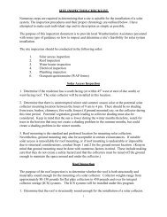
Battery Backup Grid-Connected Photovoltaic Emergency Power System Installation Notes<br />
The following is a brief summary of equipment installation notes. The owner and the installer will be provided<br />
with all manufacturers' instruction manuals as well as a copy of the materials that have been submitted to the <strong>Florida</strong> <strong>Solar</strong><br />
<strong>Energy</strong> Center for design review of the system.<br />
Summary of Major Equipment Manufacturer, Model and Listing/Compliance<br />
Note that the Outback GVFX3648 Inverters will supply a maximum of 10,800 watts if the utility grid is down. When the<br />
utility grid is up, the three inverters will pass through 50A @ 120V, or 18,000 VA. If the utility grid is down, the system<br />
operates as a stand-alone PV system and is thus subject to the provisions of NEC 690.10(A). When the utility grid is<br />
operational, the PV system loads are subject to NEC 220.<br />
Note also that the PV system can be expected to generate approximately 36 kWh per day as long as the day is mostly<br />
sunny. In the event of a utility outage, run times of loads may need to be adjusted on a daily basis to avoid having the<br />
inverter shut down if the battery state of charge reaches the minimum allowable limit of 44 volts.<br />
When the utility is in operation, the kWh consumption is no longer limited by battery capacity, since the grid will supply<br />
14,400 VA continuously (50A C.B.) via the inverter if necessary.<br />
I. PV Module Installation<br />
Item Manufacturer Model Listing<br />
PV Modules <strong>Solar</strong> World SW 240 Poly UL<br />
Source ckt Combiner<br />
Box<br />
DC Component<br />
Enclosure<br />
Outback Power<br />
Outback Power<br />
PV8<br />
FW1000DC<br />
ETL<br />
ETL<br />
GFDI Device Outback Power OBDC-GFP2 ETL<br />
Inverter Outback Power GVFX3648 ETL (to UL1741)<br />
Charge Controller Outback Power FM-80 ETL<br />
AC Component<br />
Enclosure<br />
Outback Power FW1000AC ETL<br />
Storage Batteries Sun-Xtender PVX-3050T ЯU<br />
A. Electrical Notes<br />
1. Modules are prewired with #12 PV Wire conductors with molded W/P connectors. Use only the connectors<br />
provided for connecting modules in series. Do not cut connectors off as this may void the manufacturer's<br />
warranty. Do not disconnect connectors under load.<br />
2. Module output is DC. Twist-on connectors are not suitable for use with DC. Use only the terminal strips or<br />
Polaris taps enclosed in a weatherproof junction box to transition wires if needed.<br />
3. If junction boxes are used, use cord connector strain relief at junction box entries of module open wiring<br />
conductors. Be sure connectors are tightened sufficiently to prevent water entry into the junction box along the<br />
wires.<br />
4. Use lay-in ground lugs or WEEB components for grounding modules and module racking. Mount ground lugs to<br />
modules using #10-32 self-threading stainless steel bolts, nuts and lockwashers that are provided with the lugs.<br />
Use #10 solid bare wire in continuous runs to ground modules. Removal of any module from the system must not<br />
affect the grounding of the remaining modules.<br />
5. Bond all array mounting structure to modules using approved bonding clips. Use one clip for each individual<br />
length of mounting rail.<br />
6. Strap all module open wiring neatly to the mounting frame using UV resistant wire straps.<br />
7. Follow school building code requirements for all electrical conduit and and components.<br />
8. If DC wiring passes through building interior space, NEC690.31(E) requires that the wiring be enclosed in<br />
metallic conduit up to the first readily accessible disconnecting means.<br />
B. Mechanical Notes<br />
1. Use Stainless Steel hardware to attach PV Modules to PV Array mounting frame<br />
2. Follow module mounting detail shown in mechanical drawings of mounting frame.<br />
II. Source Circuit Combiner Box Installation<br />
Follow manufacturer's instructions.<br />
III. FW1000 AC and DC Disconnect Enclosure Installation<br />
Follow manufacturer's instructions.<br />
IV. System Batteries Installation<br />
Follow manufacturer's instructions and install in accordance with NEC requirements. Maintenance free<br />
batteries will only need to be vented at the top and bottom of battery container to keep the batteries cool, as per<br />
IEEE 1187 and the terminals will need to be protected from accidental short circuits.<br />
Use only UL listed cables and cable lugs crimped with approved UL crimping tool. The use of fine stranded<br />
battery cables is highly recommended to reduce the strain on battery terminals. Do not use battery lugs that have an<br />
inspection peep hole for battery connections, as these lugs are not suitable for use with batteries.<br />
V. GVFX 3648 Inverter Installation<br />
Follow manufacturer's instructions for installation and programming via the MATE system controller.<br />
VI. MX-80 MPPT Charge Controller Installation<br />
Follow manufacturer's instructions for installation and programming via the MATE system controller.<br />
VII. Balance of System (BOS) Component Installation<br />
The balance of system components are shown on the electrical schematic diagram. These are standard AC<br />
components that require wiring according to NEC, using standard wiring practices. In particular, the point of<br />
utility connection (PUC) has been designed to meet the requirements of NEC 690.64.<br />
3232 Moss Hill Road, <strong>Vernon</strong>, FL 32462<br />
Design for:<br />
I CERTIFY THAT THIS PV<br />
SYSTEM FULLY COMPLIES<br />
WITH THE REQUIREMENTS<br />
OF NEC 690.<br />
PV SYSTEM<br />
Total Output:<br />
# Modules:<br />
Manufacturer:<br />
Model:<br />
<strong>Vernon</strong> <strong>High</strong> <strong>School</strong><br />
<strong>Solar</strong> <strong>School</strong> Shelters<br />
Battery Backup PV System<br />
Notes<br />
SCALE: NTS<br />
DRAWN BY: RB,HB<br />
CHECKED BY: EC<br />
DATE: 10/03/11<br />
SHEET 13 OF 20<br />
Revision:<br />
00<br />
10.08 kW<br />
42<br />
<strong>Solar</strong> World<br />
240<br />
Sheet:<br />
E.E. Castillo, PE<br />
Licensed Engineer #: PE52590<br />
Certification of Authorization #28406<br />
3601 N. DIXIE HWY, BAY 16 BOCA RATON, FL 33431<br />
PHONE: 561.750.8677 FAX:561.750.0518<br />
N-01
Ground Anchor<br />
and Strap<br />
5 8 " x 8'<br />
Ground Rod<br />
(driven below ground)<br />
72.00"<br />
111.00"<br />
3"x 3" x 1 4" Stainless or<br />
Galvanized Steel Post<br />
36.00" 1" Conduit<br />
72.00"<br />
48.00"<br />
Optional shed location to<br />
be Min 8' east or west of Array<br />
Note: This Drawing is intended to show array structure and equipment enclosure placement only.<br />
See Structural drawings S-1 and S-2 for Array Structural and footer details.<br />
See Sheet A01 of 07 through A07 of 07 for <strong>Solar</strong> Equipment Enclosure Structural and Anchoring (see A07 of 07)<br />
details.<br />
A<br />
Skids<br />
Concrete Block<br />
1" LB<br />
3/4" LB<br />
Meter<br />
Approx - 96.00"<br />
<strong>Solar</strong> Equipment Enclosure Location vs Array East Elevation<br />
SCALE: 1/2" = 1'-0"<br />
Treated soil beneath<br />
equipment enclosure<br />
75.00"<br />
Steel Plate<br />
20.00"± 10"<br />
12.00"<br />
36.00"<br />
68.50"<br />
3/4" Conduit<br />
For Monitoring Wires<br />
16.00"<br />
Connector/Bushings<br />
82.00"<br />
198.00"<br />
Rail<br />
C Channel<br />
1" Conduit<br />
1" Conduit<br />
68.50"<br />
Module<br />
Notes:<br />
53.00"<br />
This Drawing is<br />
intended to show<br />
Enclosure and Array<br />
Placement only.<br />
See the attached<br />
Enclosure plans for<br />
detailed enclosure<br />
specifications.<br />
20.00"±10"<br />
Legend:<br />
<strong>Solar</strong> Panel<br />
C-chanel<br />
24.00"<br />
Galvanized Post<br />
Rail<br />
N<br />
3232 Moss Hill Road, <strong>Vernon</strong>, FL 32462<br />
Design for:<br />
I CERTIFY THAT THIS PV<br />
SYSTEM FULLY COMPLIES<br />
WITH THE REQUIREMENTS<br />
OF NEC 690.<br />
PV SYSTEM<br />
Total Output:<br />
# Modules:<br />
Manufacturer:<br />
Model:<br />
<strong>Vernon</strong> <strong>High</strong> <strong>School</strong><br />
<strong>Solar</strong> <strong>School</strong> Shelters<br />
Battery Backup PV System<br />
<strong>Solar</strong> Equipment Enclosure<br />
Location vs Array<br />
SCALE: NTS<br />
DRAWN BY: RB,HB<br />
CHECKED BY: EC<br />
DATE: 10/03/11<br />
SHEET 14 OF 20<br />
Revision:<br />
00<br />
10.08 kW<br />
42<br />
<strong>Solar</strong> World<br />
240<br />
Sheet:<br />
E.E. Castillo, PE<br />
Licensed Engineer #: PE52590<br />
Certification of Authorization #28406<br />
3601 N. DIXIE HWY, BAY 16 BOCA RATON, FL 33431<br />
PHONE: 561.750.8677 FAX:561.750.0518<br />
M-01
A<br />
C<br />
3/4”<br />
Metal LB<br />
4”X4”X2”<br />
PVC<br />
Junction<br />
Box<br />
3/4” Sch 80 PVC<br />
W/ Cat 5<br />
12.75"<br />
40.5"<br />
Mate<br />
3/4” EMT<br />
Conduit<br />
Hub<br />
Input /Output<br />
Bypass Kit<br />
AC Breakers<br />
3/4” Sealing<br />
Locknut<br />
Exterior Wall Of <strong>School</strong><br />
1” EMT<br />
Conduit<br />
1”<br />
Metal LB<br />
2 Hole PVC Strap<br />
11.5"<br />
OutBack FlexWare 1000 AC<br />
Power Distribution Panel<br />
(See Sheet E-03)<br />
6”X6”X4”<br />
PVC<br />
Junction<br />
Box<br />
Power in<br />
1” Sealing<br />
Locknut<br />
AC In<br />
H<br />
N<br />
AC Out<br />
H<br />
N<br />
AC In<br />
H<br />
N<br />
AC Out<br />
H<br />
N<br />
AC In<br />
H<br />
N<br />
AC Out<br />
H<br />
N<br />
To Shed To Shed To Shed<br />
1 1/4” EMT<br />
Conduit<br />
1 1/4”<br />
Metal LB<br />
GVFX3648<br />
PV BATT PV BATT<br />
-<br />
+<br />
-<br />
+<br />
GVFX3648<br />
GVFX3648<br />
FlexWare Mounting Plate<br />
47"<br />
Conduit Tie Down bracket<br />
2 rows of 8 Batteries in series.<br />
Batteries are Sun Xtender 3050T Batteries.<br />
(See Sheet DS-03:04 for Battery Specifications).<br />
4/0 Pos Battery<br />
Cable<br />
250A Inline DC Fuse<br />
Battery Temp<br />
Sensor Wire<br />
10.25"<br />
Wall<br />
Light Fixture<br />
GFCI Outlet<br />
Ground Anchor<br />
and Strap<br />
Outback GVFX Inverter<br />
AC Adapter<br />
DC Adapter<br />
Wood Subfloor<br />
-<br />
+<br />
Utility<br />
Disconnect<br />
15.25"<br />
Skids<br />
Power out<br />
9.25"<br />
Combiner Box A<br />
(See Sheet E-02)<br />
Concrete Block<br />
96.00"<br />
1 1/4” Hub<br />
Combiner Box B<br />
(See Sheet E-02)<br />
OutBack FlexWare 1000 DC<br />
Power Distribution Panel<br />
(See Sheet E-02)<br />
FW 1000<br />
DC Enclosure<br />
DC Breakers<br />
FLEXmax<br />
FLEXmax<br />
PV BATT<br />
Combiner Box C<br />
(See Sheet E-02)<br />
FLEXmax<br />
2" Flexible Metal<br />
Conduit<br />
Outback MX 80<br />
Charge Controller<br />
Cable Raceway<br />
Entrance<br />
PV+ and Batt+ Breakers<br />
Plastic Bushing<br />
4/0 Neg Battery<br />
Cable<br />
2" Flexible Metal<br />
Conduit Connector<br />
<strong>Solar</strong> Equipment Enclosure Interior South Elevation<br />
SCALE: 1/2"=1'0" B<br />
1" Sch 80<br />
Conduit w/10 # 12 USE-2<br />
& 1 #10 ground<br />
from Array<br />
to Combiner Boxes A, B, C<br />
Entrance<br />
29"<br />
8'<br />
In From PV Array<br />
Exterior Wall Of <strong>Solar</strong> Equipment Enclosure<br />
1" LB<br />
2 Hole PVC Strap<br />
3/4"<br />
LB<br />
3/4" Sch 80 Conduit<br />
w/mon wires From Array<br />
3/4" Sch 80 Conduit<br />
W/Cat5<br />
Meter 1<br />
Meter 2<br />
Out To Building<br />
36.00"<br />
1” Sch 80 PVC<br />
W/4 #6 &<br />
1 #10 Ground<br />
1 1/4” Sch 80 PVC<br />
W/ 4 #4 &<br />
1 #10 Ground<br />
1 1/4" Sch 80 1" Sch 80 Conduit<br />
Conduit<br />
w/4 #6, &<br />
w/4 #4 and 1 #10 Ground To<br />
Note: Use caulking<br />
around all wall<br />
penetrations.<br />
1 #10<br />
Ground To<br />
Building<br />
18” below grade<br />
Building<br />
18” below grade<br />
96.00"<br />
Combiner Box A<br />
(See Sheet E-02)<br />
1" Conduit from Array<br />
Single Door Entrance<br />
1" LB<br />
1" Conduit<br />
Combiner Box A<br />
(See Sheet E-02)<br />
<strong>Solar</strong> Equipment Enclosure Layout<br />
SCALE: 1/2" = 1'0"<br />
<strong>School</strong> Wall Connections<br />
<strong>Solar</strong> Equipment Enclosure North Elevation<br />
SCALE: 3/8"=1'0" D SCALE: 3/8"=1'0"<br />
E<br />
PV<br />
ARRAY<br />
Flexware<br />
Mounting<br />
Plate<br />
30.00"<br />
96.00"<br />
FlexWare 1000 DC Enclosure<br />
FlexWare 1000 AC Enclosure<br />
12.75"<br />
Combiner Box A<br />
(See Sheet E-02)<br />
PV<br />
ARRAY<br />
7"<br />
Meter 1 Meter 2<br />
Cat5 Wire Out<br />
Monitoring Wires From Array<br />
1'-4"<br />
4"<br />
Outback Combiner Box<br />
FlexWare 1000 AC Enclosure<br />
36.00"<br />
36.00"<br />
Minimum clearance needed<br />
Outback GVFX<br />
3648 Inverter<br />
Battery Bank<br />
2 Rows of<br />
8 Batteries in Series<br />
Wood Subfloor<br />
Skids<br />
Concrete Block<br />
72.00"<br />
Wall<br />
72.00"<br />
72.00"<br />
Vent (Mechanical-Optional)<br />
<strong>Solar</strong> Equipment Enclosure West Elevation<br />
SCALE: 3/8"=1'0"<br />
Light Fixture<br />
GFCI Outlet<br />
96.00"<br />
Ground Anchor<br />
and Strap<br />
N<br />
Notes:<br />
N<br />
This Drawing is<br />
intended to show<br />
equipment placement<br />
inside of enclosure<br />
only.<br />
See the attached<br />
enclosure plans for<br />
detailed enclosure<br />
specifications.<br />
3232 Moss Hill Road, <strong>Vernon</strong>, FL 32462<br />
Design for:<br />
I CERTIFY THAT THIS PV<br />
SYSTEM FULLY COMPLIES<br />
WITH THE REQUIREMENTS<br />
OF NEC 690.<br />
PV SYSTEM<br />
Total Output:<br />
# Modules:<br />
Manufacturer:<br />
Model:<br />
<strong>Vernon</strong> <strong>High</strong> <strong>School</strong><br />
<strong>Solar</strong> <strong>School</strong> Shelters<br />
Battery Backup PV System<br />
<strong>Solar</strong> Equipment Enclosure<br />
<strong>School</strong> Wall Detail<br />
SCALE: NTS<br />
DRAWN BY: RB,HB<br />
CHECKED BY: EC<br />
DATE: 10/03/11<br />
SHEET 15 OF 20<br />
Revision:<br />
00<br />
10.08 kW<br />
42<br />
<strong>Solar</strong> World<br />
240<br />
Sheet:<br />
E.E. Castillo, PE<br />
Licensed Engineer #: PE52590<br />
Certification of Authorization #28406<br />
3601 N. DIXIE HWY, BAY 16 BOCA RATON, FL 33431<br />
PHONE: 561.750.8677 FAX:561.750.0518<br />
M-02
3232 Moss Hill Road, <strong>Vernon</strong>, FL 32462<br />
Design for:<br />
I CERTIFY THAT THIS PV<br />
SYSTEM FULLY COMPLIES<br />
WITH THE REQUIREMENTS<br />
OF NEC 690.<br />
PV SYSTEM<br />
Total Output:<br />
# Modules:<br />
Manufacturer:<br />
Model:<br />
<strong>Vernon</strong> <strong>High</strong> <strong>School</strong><br />
<strong>Solar</strong> <strong>School</strong> Shelters<br />
Battery Backup PV System<br />
PV Watts<br />
SCALE: NTS<br />
DRAWN BY: RB,HB<br />
CHECKED BY: EC<br />
DATE: 10/03/11<br />
SHEET 16 OF 20<br />
Revision:<br />
00<br />
10.08 kW<br />
42<br />
<strong>Solar</strong> World<br />
240<br />
Sheet:<br />
E.E. Castillo, PE<br />
Licensed Engineer #: PE52590<br />
Certification of Authorization #28406<br />
3601 N. DIXIE HWY, BAY 16 BOCA RATON, FL 33431<br />
PHONE: 561.750.8677 FAX:561.750.0518<br />
P-01
<strong>Solar</strong> Panel - Inverter Data Sheet<br />
SCALE: NTS<br />
3232 Moss Hill Road, <strong>Vernon</strong>, FL 32462<br />
Design for:<br />
I CERTIFY THAT THIS PV<br />
SYSTEM FULLY COMPLIES<br />
WITH THE REQUIREMENTS<br />
OF NEC 690.<br />
PV SYSTEM<br />
Total Output:<br />
# Modules:<br />
Manufacturer:<br />
Model:<br />
<strong>Vernon</strong> <strong>High</strong> <strong>School</strong><br />
<strong>Solar</strong> <strong>School</strong> Shelters<br />
Battery Backup PV System<br />
Data Sheet<br />
SCALE: NTS<br />
DRAWN BY: RB,HB<br />
CHECKED BY: EC<br />
DATE: 10/03/11<br />
SHEET 17 OF 20<br />
Revision:<br />
00<br />
10.08 kW<br />
42<br />
<strong>Solar</strong> World<br />
240<br />
Sheet:<br />
E.E. Castillo, PE<br />
Licensed Engineer #: PE52590<br />
Certification of Authorization #28406<br />
3601 N. DIXIE HWY, BAY 16 BOCA RATON, FL 33431<br />
PHONE: 561.750.8677 FAX:561.750.0518<br />
DS-01
Charge Controller - Combiner Box Data Sheet<br />
SCALE: NTS<br />
3232 Moss Hill Road, <strong>Vernon</strong>, FL 32462<br />
Design for:<br />
I CERTIFY THAT THIS PV<br />
SYSTEM FULLY COMPLIES<br />
WITH THE REQUIREMENTS<br />
OF NEC 690.<br />
PV SYSTEM<br />
Total Output:<br />
# Modules:<br />
Manufacturer:<br />
Model:<br />
<strong>Vernon</strong> <strong>High</strong> <strong>School</strong><br />
<strong>Solar</strong> <strong>School</strong> Shelters<br />
Battery Backup PV System<br />
Data Sheet<br />
SCALE: NTS<br />
DRAWN BY: RB,HB<br />
CHECKED BY: EC<br />
DATE: 10/03/11<br />
SHEET 18 OF 20<br />
Revision:<br />
00<br />
10.08 kW<br />
42<br />
<strong>Solar</strong> World<br />
240<br />
Sheet:<br />
E.E. Castillo, PE<br />
Licensed Engineer #: PE52590<br />
Certification of Authorization #28406<br />
3601 N. DIXIE HWY, BAY 16 BOCA RATON, FL 33431<br />
PHONE: 561.750.8677 FAX:561.750.0518<br />
DS-02
Battery Data Sheet<br />
SCALE: NTS<br />
3232 Moss Hill Road, <strong>Vernon</strong>, FL 32462<br />
Design for:<br />
I CERTIFY THAT THIS PV<br />
SYSTEM FULLY COMPLIES<br />
WITH THE REQUIREMENTS<br />
OF NEC 690.<br />
PV SYSTEM<br />
Total Output:<br />
# Modules:<br />
Manufacturer:<br />
Model:<br />
<strong>Vernon</strong> <strong>High</strong> <strong>School</strong><br />
<strong>Solar</strong> <strong>School</strong> Shelters<br />
Battery Backup PV System<br />
Data Sheet<br />
SCALE: NTS<br />
DRAWN BY: RB,HB<br />
CHECKED BY: EC<br />
DATE: 10/03/11<br />
SHEET 19 OF 20<br />
Revision:<br />
00<br />
10.08 kW<br />
42<br />
<strong>Solar</strong> World<br />
240<br />
Sheet:<br />
E.E. Castillo, PE<br />
Licensed Engineer #: PE52590<br />
Certification of Authorization #28406<br />
3601 N. DIXIE HWY, BAY 16 BOCA RATON, FL 33431<br />
PHONE: 561.750.8677 FAX:561.750.0518<br />
DS-03
Battery Specifications - Data Sheet<br />
SCALE: NTS<br />
3232 Moss Hill Road, <strong>Vernon</strong>, FL 32462<br />
Design for:<br />
I CERTIFY THAT THIS PV<br />
SYSTEM FULLY COMPLIES<br />
WITH THE REQUIREMENTS<br />
OF NEC 690.<br />
PV SYSTEM<br />
Total Output:<br />
# Modules:<br />
Manufacturer:<br />
Model:<br />
<strong>Vernon</strong> <strong>High</strong> <strong>School</strong><br />
<strong>Solar</strong> <strong>School</strong> Shelters<br />
Battery Backup PV System<br />
Data Sheet<br />
SCALE: NTS<br />
DRAWN BY: RB,HB<br />
CHECKED BY: EC<br />
DATE: 10/03/11<br />
SHEET 20 OF 20<br />
Revision:<br />
00<br />
10.08 kW<br />
42<br />
<strong>Solar</strong> World<br />
240<br />
Sheet:<br />
E.E. Castillo, PE<br />
Licensed Engineer #: PE52590<br />
Certification of Authorization #28406<br />
3601 N. DIXIE HWY, BAY 16 BOCA RATON, FL 33431<br />
PHONE: 561.750.8677 FAX:561.750.0518<br />
DS-04