SunSmart E-Shelter Operations Manual & PV System Overview
SunSmart E-Shelter Operations Manual & PV System Overview
SunSmart E-Shelter Operations Manual & PV System Overview

You also want an ePaper? Increase the reach of your titles
YUMPU automatically turns print PDFs into web optimized ePapers that Google loves.
<strong>SunSmart</strong> E-<strong>Shelter</strong><br />
<strong>Operations</strong> <strong>Manual</strong> &<br />
<strong>PV</strong> <strong>System</strong> <strong>Overview</strong><br />
For Facilities Managers & School Personnel<br />
<strong>System</strong> Commissioning Date:_______ FSEC Approval Number:_____<br />
WARNING<br />
DANGER - HIGH VOLTAGE<br />
DO NOT SERVICE WHEN WET<br />
HAZARDOUS MATERIAL - ACID
ACKNOWLEDGMENT<br />
This material is based upon work supported by the U.S. Department of<br />
Energy and the Florida Energy and Climate Commission under Award<br />
Number DE-EE0000241.<br />
DISCLAIMER: “This report was prepared as an account of work sponsored<br />
by an agency of the United States Government. Neither the United States<br />
Government nor any agency thereof, nor any of their employees, nor any<br />
of their contractors, subcontractors or their employees, makes any<br />
warranty, express or implied, or assumes any legal liability or<br />
responsibility for the accuracy completeness or any third party’s use of the<br />
results of such use of any information, apparatus, product, or process<br />
disclosed, or represents that its use would not infringe privately owned<br />
rights. Reference herein to any specific commercial product, process, or<br />
service by trade name, trademark, manufacturer, or otherwise, does not<br />
necessarily constitute or imply its endorsement, recommendation, or<br />
favoring by the United States Government or any agency thereof or its<br />
contractors or subcontractors. The views and opinions of authors<br />
expressed herein do not necessarily state or reflect those of the United<br />
States Government or any agency thereof”.
IMPORTANT: PLEASE READ<br />
Please carefully read all safety instructions and operations &<br />
maintenance procedures contained within this manual to<br />
ensure safe and proper operation of the <strong>PV</strong> system.<br />
Keep flammable liquids away from the shed and solar array at<br />
all times. Use extreme caution whenever working around<br />
electricity, electrical components, and batteries. There is<br />
always a potential for shocks, burns, injury, and even death if<br />
you come in contact with electricity.<br />
TROUBLESHOOTING<br />
If you experience problems with the photovoltaic (<strong>PV</strong>) system, please<br />
contact VB Engineering BEFORE performing any service repairs due to<br />
malfunctions or damage .<br />
For any problems or questions after the 5-year warranty period expires<br />
(effective through August 31, 2016), please contact the <strong>SunSmart</strong> Program<br />
at the Florida Solar Energy Center and VB Engineering.<br />
VB Engineering<br />
Office: 561-750-8677<br />
Email: sunsmart@vbengineering.com<br />
<strong>SunSmart</strong> E-<strong>Shelter</strong>s c/o the Florida Solar Energy Center<br />
Office: 321-252-9479<br />
Email: sunsmart@fsec.ucf.edu
TABLE OF CONTENTS<br />
Safety Information 1<br />
<strong>SunSmart</strong> E-<strong>Shelter</strong>s Project <strong>Overview</strong> 2<br />
<strong>PV</strong> <strong>System</strong> <strong>Overview</strong> 3<br />
Solar Array & Shed <strong>Overview</strong> 4<br />
Inverter/Charge Controller <strong>Overview</strong> 5<br />
Data Acquisition <strong>System</strong> <strong>Overview</strong> 6<br />
Energy Production & Cost Savings 7<br />
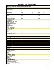
Annual Inspection Checklist & Maintenance Procedures 8-9<br />
Battery Safety Information 10<br />
Startup Procedures 11<br />
Shutdown Procedures & Location of Disconnects 12-14<br />
Warranty Information 15-18<br />
Solar Panel Specifications 19-20<br />
Inverter/Charge Controller Specifications 21-25<br />
Balance of <strong>System</strong> (BOS) Components 26-30<br />
Battery <strong>Overview</strong> and Specifications 31-35
SAFETY INFORMATION<br />
WARNING<br />
Hazardous Voltage<br />
Risk of Electric Shock: The connection of several solar panels in series<br />
results in the adding up of voltage and imposes danger.<br />
Arcing Warning: Solar panels generate direct current (DC) when exposed<br />
to light. When breaking a closed circuit, a dangerous arc may be<br />
generated. Do not cut any live wires.<br />
Suitable Ambient Conditions: Solar panels must not be exposed to<br />
focused light. The module must neither be immersed in water nor be<br />
exposed to continuous wetting (e.g. by fountains). Exposure to salt or<br />
sulfur implies a risk of corrosion.<br />
WARNING<br />
Hazardous Material: Corrosive Chemicals<br />
Do not open batteries. Avoid contact with internal components. Internal<br />
components include lead and liquid electrolyte.<br />
Electrolyte - Electrolyte is corrosive and contact may cause skin irritation<br />
and chemical burns. Electrolyte causes severe irritation and burns of<br />
eyes, nose and throat. Ingestion can cause severe burns and vomiting.<br />
Lead - Direct skin or eye contact may cause local irritation. Inhalation or<br />
ingestion of lead dust or fumes may result in headache, nausea,<br />
vomiting, abdominal spasms, fatigue, sleep disturbances, weight loss,<br />
anemia and leg, arm and joint pain.<br />
Occupation Safety and Health Administration (OHSA) Requirements<br />
1926.441(a)(5) - Face shields, aprons, and rubber gloves shall be<br />
provided for workers handling acids or batteries.<br />
1926.441(a)(6) - Facilities for quick drenching of the eyes and body shall<br />
be provided within 25 feet (7.62 m) of battery handling areas.<br />
1
SUNSMART E-SHELTERS PROJECT OVERVIEW<br />
The <strong>SunSmart</strong> E-<strong>Shelter</strong>s Project is part of $10M grant awarded to the Florida Solar Energy<br />
Center (a research institute of the University of Central Florida) through the American Recovery<br />
and Reinvestment Act of 2009 (ARRA) to increase deployment of solar energy systems to schools,<br />
colleges, and other public buildings.<br />
The <strong>SunSmart</strong> E-<strong>Shelter</strong>s Project provides solar energy systems of approximately 10kW to 90<br />
public schools/colleges that have been designated by the state as enhanced hurricane protection<br />
area (EHPA) shelters. These systems feature a battery back-up that provides emergency power<br />
to the shelter in the event of an electrical power outage.<br />
Each school designated as a <strong>SunSmart</strong> E-<strong>Shelter</strong> will also receive a solar energy curriculum for<br />
students along with specialized training for teachers and school personnel.<br />
2
<strong>PV</strong> SYSTEM OVERVIEW<br />
This system is a grid-tied <strong>PV</strong> system with battery backup, with <strong>PV</strong> generation consisting of 42<br />
SolarWorld SW-240 modules with a combined STC rated DC output power of 10,080 watts. The<br />
modules are connected into two groups of five 3-module source circuits and one group of four 3module<br />
source circuits that feed three OutBack FM80 charge controllers. The charge controllers<br />
feed the system batteries and the inverters which are connected to supply 120/208 volt AC<br />
(uninterruptible) to the standby loads and also the utility grid. The system is provided with all<br />
disconnects and labels required by the National Electrical Code. The system batteries are sized<br />
for 610 amp hours at 48V providing approximately 27.0kWh to standby (uninterruptible) loads.<br />
When the sun is shining, power from the <strong>PV</strong> array is used to keep the batteries fully charged.<br />
After charging the batteries, the <strong>PV</strong> power is made available to the standby loads. If the <strong>PV</strong><br />
power meets the requirements of the standby loads, any remaining <strong>PV</strong> power is then directed to<br />
the interruptible loads of the occupancy. If any <strong>PV</strong> power remains after the interruptible loads<br />
have been powered, it is delivered to the utility. When utility power is available, but <strong>PV</strong> power<br />
is not available, standby loads are supplied by the utility. If neither utility or <strong>PV</strong> power is<br />
available, standby loads are supplied by the batteries. Thus, the batteries are only cycled if<br />
utility power is lost. The batteries used are specially designed, deep cycle, maintenance free<br />
batteries that are capable of undergoing approximately 3,000-4,000 charge-discharge cycles.<br />
Designing the system to minimize battery cycling extends the life of the batteries.<br />
On an average day of Florida sunshine, the system will produce approximately 36.5kWh of clean<br />
energy.<br />
3
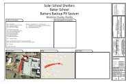
SOLAR ARRAY & SHED OVERVIEW<br />
The SOLAR ARRAY is comprised of 42 SolarWorld<br />
240 watt polycrystalline solar modules.<br />
The SOLAR EQUIPMENT ENCLOSURE houses the<br />
inverters, batteries, and charge controllers.<br />
4
INVERTER/CHARGE CONRTOLLER OVERVIEW<br />
The FLEXware 1000 system architecture is capable of supporting three<br />
OutBack GVFX-3648 Inverters, three OutBack FM-80 Charge Controllers,<br />
and all the required AC and DC components and wiring.<br />
OutBack GVFX-3648<br />
Inverters<br />
Mate2 <strong>System</strong> Display<br />
and Controller<br />
5<br />
OutBack FM-80<br />
Charge Controllers
DATA ACQUISITION SYSTEM OVERVIEW<br />
greenMonitor (closed) greenMonitor (open)<br />
The <strong>PV</strong> system performance and operation is measured and monitored by an automated data<br />
acquisition system (DAS). The DAS is externally interfaced with the <strong>PV</strong> system to collect the<br />
following data:<br />
•Site meteorological data:<br />
a. Plane-of-array irradiance<br />
b. Ambient temperature<br />
c. Module temperature<br />
d. Wind speed<br />
•Site measured data:<br />
a. Battery voltage<br />
b. Battery current<br />
c. <strong>PV</strong> array voltage<br />
d. <strong>PV</strong> array current<br />
e. Energy production from the <strong>PV</strong> system<br />
f. Energy consumption of critical load panel<br />
g. Power production from the <strong>PV</strong> system<br />
h. Power consumption of critical load panel<br />
Please DO NOT attempt to service and/or program the data acquisition system. For all inquiries,<br />
please contact the system installer (Vergona-Bowersox Electric) at 561-750-8677.<br />
6<br />
Stevenson Screen<br />
(Instrument <strong>Shelter</strong>)
ENERGY PRODUCTION & COST SAVINGS<br />
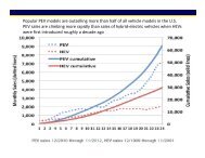
<strong>PV</strong> Watts is a performance calculator for grid-connected <strong>PV</strong> systems. The monthly and yearly<br />
energy production are modeled using the selected <strong>PV</strong> system parameters and weather data that<br />
are typical or representative of long-term averages. Because weather patterns vary from year-toyear,<br />
the values in the tables are better indicators of long-term performance than performance for<br />
a particular month or year. <strong>PV</strong> performance is largely proportional to the amount of solar radiation<br />
received, which may vary from the long-term average by 30% for monthly values and 10% for<br />
yearly values.<br />
7
Solar Panels<br />
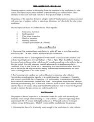
ANNUAL INSPECTION CHECKLIST<br />
Please make sure to read the safety information (page 1)<br />
before performing an inspection of the <strong>PV</strong> system,<br />
1. All fixtures are securely tightened (torque setting of 11.8 ft.-lbs.) and corrosion-free.<br />
2. Wiring is securely connected, properly arranged and free of corrosion.<br />
3. Cables are free of damage.<br />
4. Please also observe applicable standards.<br />
5. Cleaning: On principle, the modules do not need any cleaning since the tilt angle is<br />
sufficient (> 15 ; self-cleaning by rain). In case of heavy contamination or during long<br />
periods without rainfall, we recommend cleaning the modules with plenty of water<br />
(hose) WITHOUT the addition of cleaning agents but application of a soft cleaning device<br />
(sponge). NEVER scrape or rub off dirt; this may result in micro-scratches. DO NOT use a<br />
pressure cleaner to clean the modules.<br />
Inverters & Charge Controllers<br />
(see page 6 for location of disconnects)<br />
1. Turn off all circuit breakers before doing any cleaning or adjustments.<br />
2. Please be extremely careful when cleaning the outside/surface of the inverters and<br />
charge controllers to ensure that any buttons are not accidentally pushed which could<br />
lead to the improper programming of the <strong>PV</strong> system. Please also use caution to make<br />
sure display panels are not damaged in the cleaning and inspection processes.<br />
3. Clean the outside of the inverter and the filter using a damp sponge to wipe away dirt<br />
from the inverter’s surface.<br />
4. Follow manufacturer’s instructions on removing the cover of the inverter when<br />
cleaning the filter.<br />
5. Check vents on all charge controllers to make sure they are free from dust and debris.<br />
Racking, Wiring, & Shed<br />
1. Make sure that all nuts and bolts in the array mounting structure are tight and<br />
secure.<br />
2. Make sure metal surfaces are free of corrosion.<br />
3. Check electrical cable connections to make sure they are tight and secure.<br />
8
ANNUAL INSPECTION CHECKLIST<br />
Please make sure to read the safety information (page 1)<br />
before performing an inspection of the <strong>PV</strong> system,<br />
4. Check all exposed wiring for scrapes and make sure that cables are not damaged.<br />
5. Make sure there is no moisture on the floor of the shed.<br />
6. Finally, check that there is continuity between module frames and earth ground.<br />
Batteries (please see battery safety information on page 11 BEFORE<br />
performing an inspection of the batteries<br />
1. Always wear protective clothing - batteries contain acid and any spillage will damage<br />
your clothes and burn your skin.<br />
2. Clean the batteries around the terminals and ensure that the area is grease-free.<br />
3. Clean any deposits that from around the terminals with warm water and coat the<br />
terminals with a petroleum jelly or product specifically for the purpose.<br />
4. Never totally discharge a battery as it is unlikely you will be able to recharge it back to<br />
it's original state. In practice it is best not to let the battery discharge to less than 85%<br />
of it's capacity. Using a direct current voltmeter check the state of charge. 12.6 volts<br />
or above indicates a fully charged 12v battery, 12.3 volts means it is approximately<br />
half charged and anything less than 11 volts means the battery is very flat and may<br />
not ever recover. The predicted life of a battery very much depends on it's use and<br />
state of charge. Since batteries are only used when the utility is lost, and solar is not<br />
available, the batteries are expected to last well beyond the manufacturer’s warranty<br />
period.<br />
9
BATTERY SAFETY INFORMATION<br />
10
START UP PROCEDURES<br />
Note: Failure to follow correct sequencing in startup and shutdown may<br />
result in permanent damage to inverters or charge controllers. Please<br />
carefully review all start-up & shut-down procedures.<br />
TO START UP THE SYSTEM, perform the shut-down sequence in opposite order.<br />
Note that in the start-up sequence, the charge controller OUTPUT circuit breakers are turned on<br />
before the charge controller INPUT breakers are turned on. After turning on the charge controller<br />
output breakers, observe the charge controller displays to see if they are directing the operator<br />
to make any decisions, such as setting the nominal battery voltage. OutBack charge controllers<br />
actually direct the user to turn on the <strong>PV</strong> array when all preliminary charge controller settings<br />
have been made. With FM-80 charge controllers, it is up to the operator to make the decisions.<br />
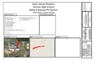
Equipment Locations Diagram<br />
11
SHUTDOWN PROCEDURES<br />
Note: Failure to follow correct sequencing in startup and shutdown may<br />
result in permanent damage to inverters or charge controllers. Please<br />
carefully review all start-up & shut-down procedures.<br />
TO TURN THE ENTIRE SYSTEM OFF, including the emergency load<br />
supply (Inverter AC Out), use the following switching sequence (see page 13 of this<br />
<strong>Operations</strong> <strong>Manual</strong> for locations of disconnects):<br />
1. Turn off the point of utility connection circuit breaker in the main distribution panel.<br />
2. Turn off the lockable utility disconnect.<br />
3. Turn off the AC IN circuit breaker.<br />
4. Turn off the 175 A inverter input disconnects.<br />
5. Turn off the circuit breakers between the <strong>PV</strong> output from the source circuit combiner box<br />
and the charge controller input terminals (labeled <strong>PV</strong> Output or Charge Controller Input).<br />
IMPORTANT: If the charge controller output circuit breakers are turned off before the<br />
charge controller input breakers are turned off, the charge controller can be permanently<br />
damaged! The reason is because the charge controller electronics are powered by the<br />
connection to the batteries through the charge controller output breakers.<br />
6. Turn off the charge controller output circuit breakers.<br />
TO TURN OFF THE <strong>PV</strong> SYSTEM BUT MAINTAIN UTILITY<br />
VOLTAGE TO THE EMERGENCY LOADS:<br />
See Page 2<br />
12
LOCATION OF DISCONNECTS<br />
13
SHUTDOWN PROCEDURES<br />
Note: Failure to follow correct sequencing in startup and shutdown may<br />
result in permanent damage to inverters or charge controllers. Please<br />
carefully review all start-up & shut-down procedures.<br />
TO TURN OFF THE <strong>PV</strong> SYSTEM BUT MAINTAIN UTILITY<br />
VOLTAGE TO THE EMERGENCY LOADS, use the following switching<br />
sequence (see page 13 of this <strong>Operations</strong> <strong>Manual</strong> for locations of disconnects):<br />
1. Turn the inverter by-pass switch to by-pass position.<br />
2. Turn off the inverter AC IN disconnect in the FW1000- AC enclosure.<br />
3. Turn off the 175 A inverter input disconnects in the FW1000-DC enclosure.<br />
4. Leave the utility disconnect and point of utility connection switches on to be sure utility<br />
power is supplied to the inverter bypass switch.<br />
These 4 steps remove all AC and DC power from the inverter. Additional shut-down may include<br />
(be sure to perform in the indicated order):<br />
5. Turn off the Charge Controller input (<strong>PV</strong> output) circuit disconnects in the DC<br />
enclosure. This removes all power from the <strong>PV</strong> arrays to the charge controllers.<br />
6. Turn off the Charge Controller output circuit breakers in the FW1000-DC Enclosure. This<br />
removes all power from the batteries to the Charge Controller.<br />
7. Turn off the circuit breakers in the FW<strong>PV</strong>-8 Source Circuit Combiner Box. This operation<br />
isolates the source circuits from each other.<br />
14
VB Engineering, Inc. fully guarantees all items hereunder against defect<br />
in materials and/or workmanship for the manufacturer’s normal period<br />
of time from the date of acceptance by the <strong>SunSmart</strong> Program at the<br />
Florida Solar Energy Center. This includes a five (5) year complete<br />
system-level warranty and service contract for the no-cost replacement<br />
of any defective component required for safe and as-specified system<br />
operation.<br />
Solar Panels<br />
10-Year Limited Product Warranty<br />
25-Year Limited Service Warranty<br />
Inverters<br />
5-Year Limited Product Warranty<br />
Batteries<br />
5-Year Limited Warranty<br />
WARRANTY INFORMATION<br />
5-Year Complete <strong>System</strong>-Level Warranty<br />
Contact Information<br />
VB Engineering<br />
3601 N. Dixie Hwy #16<br />
Boca Raton, FL 33431<br />
15<br />
T: 561-750-8677<br />
F: 561-750-0518<br />
E: sunsmart@vbengineering.com<br />
URL: www.vbengineering.com<br />
Manufacturers’ Warranty Information<br />
For details and contact info, please<br />
see page 16<br />
For details and contact info, please<br />
see pages 17<br />
For details and contact info, please<br />
see page 18
SUN-XTENDER BATTERY OVERVIEW<br />
Sun-Xtender <strong>PV</strong>X-3050T<br />
Non-spillable construction prohibits any electrolyte leaking or spewing,<br />
allowing the battery to be used upright or on its end or side. The<br />
maintenance free AGM design means no water replenishment - ever.<br />
Utilizing pure lead calcium grids, the Sun Xtender battery plates are<br />
thicker than the industry standard for longer cycle life, increased<br />
reliability and power. The low impedance AGM design allows for<br />
excellent charge acceptance and there is no current limit required with<br />
controlled voltage charging.<br />
The Sun Xtender Battery product line features proprietary PolyGuard<br />
Microporous Polyethylene Separators, shielding the positive plates<br />
against shorting, shock or vibration. No other manufacturers offer this<br />
dual layer insulation protection feature.<br />
Sun Xtender Battery covers and<br />
containers are uniquely molded with<br />
high impact, reinforced copolymer<br />
polypropylene and are designed with<br />
thick end walls to prevent bulging.<br />
The copper alloy T Terminals are<br />
corrosion resistant and are supplied<br />
with silicon bronze bolts and washers.<br />
31
SUN-XTENDER BATTERY SPECIFICATIONS<br />
32
ADDITIONAL NOTES
ADDITIONAL NOTES
ADDITIONAL NOTES
<strong>SunSmart</strong> E-<strong>Shelter</strong><br />
<strong>Operations</strong> <strong>Manual</strong> &<br />
<strong>PV</strong> <strong>System</strong> <strong>Overview</strong><br />
For Facilities Managers & School Personnel<br />
WARNING<br />
DANGER - HIGH VOLTAGE<br />
DO NOT SERVICE WHEN WET<br />
HAZARDOUS MATERIAL - ACID