
Create successful ePaper yourself
Turn your PDF publications into a flip-book with our unique Google optimized e-Paper software.
1<br />
םירטליפה םג ןכו , HPLC<br />
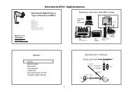
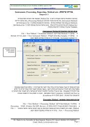
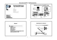
Preparing to Run <strong>UPLC</strong>; Injection and Detection Paramters<br />
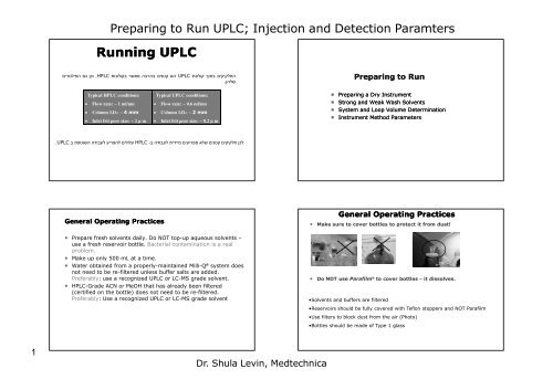
<strong>Running</strong> <strong>UPLC</strong><br />
תונולוקב רשאמ הברהב םינטק םה <strong>UPLC</strong> תנולוק ךותב םיקיקלחה<br />
. ןהלש<br />
Typical HPLC conditions:<br />
• Flow rate: ~ 1 ml/mn<br />
• Column I.D.: ~ 4 mm<br />
• Inlet frit pore size: ~ 2 µ m<br />
Typical <strong>UPLC</strong> conditions:<br />
• Flow rate: ~ 0.6 ml/mn<br />
• Column I.D.: ~ 2 mm<br />
• Inlet frit pore size: ~ 0.2 µ m<br />
. <strong>UPLC</strong> ב תפטושה הדובעל עירפהל םילולע HPLC -ב<br />
הדובעל תידיימ םיעירפמ אלש םינטק םיקיקלח ןכל<br />
General Operating Practices<br />
Prepare fresh solvents daily. Do NOT top-up aqueous solvents –<br />
use a fresh reservoir bottle. Bacterial contamination is a real<br />
problem.<br />
Make up only 500 mL at a time.<br />
Water obtained from a properly-maintained Milli-Q ® system does<br />
not need to be re-filtered unless buffer salts are added.<br />
Preferably: use a recognized <strong>UPLC</strong> or LC-MS grade solvent.<br />
HPLC-Grade ACN or MeOH that has already been filtered<br />
(certified on the bottle) does not need to be re-filtered.<br />
Preferably: Use a recognized <strong>UPLC</strong> or LC-MS grade solvent<br />
Dr. Shula Levin, Medtechnica<br />
Preparing to Run<br />
Preparing a Dry Instrument<br />
Strong and Weak Wash Solvents<br />
System and Loop Volume Determination<br />
Instrument Method Parameters<br />
General Operating Practices<br />
Make sure to cover bottles to protect it from dust!<br />
Do NOT use Parafilm ® to cover bottles – it dissolves.<br />
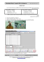
•Solvents and buffers are filtered<br />
•Reservoirs should be fully covered with Teflon stoppers and NOT Parafilm<br />
•Use filters to block dust from the air (Photo)<br />
•Bottles should be made of Type 1 glass
2<br />
Preparing to Run <strong>UPLC</strong>; Injection and Detection Paramters<br />
General Operating Recommendations<br />
Use only Pyrex (Borosilicate 3.3) bottles. DURAN bottles<br />
dissolve at high pH (>9).<br />
Use highest quality solvents, water, buffers and additives.<br />
Flush buffers out of system with water after use (use 10-20%<br />
organic in water for storage).<br />
Keep all 4 solvent lines primed (use 10-20% organic in water for<br />
unused lines).<br />
Keep seal wash primed.<br />
Re-prime solvent lines before starting.<br />
Use 100 µL mixer for TFA/ACN gradients at low wavelengths.<br />
Solvent Filters<br />
Critical Clean<br />
Stainless Steel (7 pack)700003616<br />
Stainless Steel (1/pk) 700003615<br />
Titanium (7 pack) 700003530<br />
Titanium (1 pack) 700003546<br />
Solvent filter assembly 289002172<br />
Solvent filter insert 5 µm 700002756<br />
PAT (PEEK Alloyed with Teflon) filter<br />
PSL901292 2 µm<br />
PSL901294 5 µm<br />
Dr. Shula Levin, Medtechnica<br />
CORNING PYREX ® Type 1, Class A, Borosilicate Bottles<br />
SCHOTT DURAN ® Borosilicate Glass 3.3 Bottles<br />
Mobile Phase Preparation<br />
Filtration on membrane:<br />
Also: if Biolab solvents: Use ULC/MS grade only!<br />
Actions : Solvent degassing and filtration<br />
— Potential of impurities in filtration<br />
o GHP, PTFE, Nylon, or PVDF<br />
— Pores diameter : 0.2 µm.<br />
— Volatile additives may evaporate.<br />
NOTE: Refer to ‘Controlling Contamination in<br />
UltraPerformance LC/MS and HPLC Systems’<br />
715001307D available from Waters Corp.
3<br />
Bottle Caps<br />
Preparing to Run <strong>UPLC</strong>; Injection and Detection Paramters<br />
WAT062341 4 L bottle (large neck)<br />
WAT062479 1 L bottle (small neck)<br />
No Parafilm ® or other plastic films to cover solvent reservoirs<br />
Daily Startup<br />
Set up each module in turn:<br />
—Solvent Manager:<br />
o Prime the solvent lines (2 mins each).<br />
o Set analytical flow to equilibrate column.<br />
—Sample Manager:<br />
o Prime wash and sample syringes (6 cycles).<br />
o Characterize needle seal and system volume.<br />
—Detector:<br />
o Turn on lamp (needs >½ hr).<br />
o Check and record reference and sample energy.<br />
Can do these operations simultaneously<br />
Use the System Startup Button<br />
Dr. Shula Levin, Medtechnica<br />
Startup the System According to Instructions<br />
http://www.forumsci.co.il/HPLC/<strong>UPLC</strong>_setup_21-9_09_Empower.pdf<br />
Recommended Solvents List<br />
ACQUITY <strong>UPLC</strong> System recommended Solvents<br />
Methanol Methanol/water mixtures<br />
Water Acetonitrile/water mixtures<br />
Acetonitrile (ACN) Isopropanol (IPA)<br />
Sample diluents (in addition to the solvents listed above)<br />
Dimethyl sulfoxide (DMSO) Dimethylformamide (DMF)<br />
Additives / Modifiers<br />
0.2% formic acid 0.1% trifluoroacetic acid (TFA)<br />
0.1% triethyl amine (TEA) 0.1% hexafluorobuteric acid<br />
10mM phosphate buffer 10mM ammonium bicarbonate<br />
50mM ammonium hydroxide 50mM ammonium acetate<br />
0.1% Ethylenediaminetetraacetic acid (EDTA)<br />
Cleaners<br />
Phosphoric acid (=30%) Sodium hydroxide (=1M)<br />
ACQUITY <strong>UPLC</strong> System non-recommended Solvents<br />
Methylene-Chloride Chloroform<br />
Strong acids >5%<br />
Ethyl Acetate Toluene<br />
Chlorinated solvents: (Trichlorobenzene)
4<br />
0.040<br />
0.030<br />
0.020<br />
AU<br />
0.010<br />
0.000<br />
-0.010<br />
Preparing to Run <strong>UPLC</strong>; Injection and Detection Paramters<br />
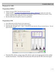
Injection Parameters<br />
Mounting of the loop<br />
MUST BE PROPER!!<br />
5.605.705.805.906.006.106.206.306.40<br />
Minutes<br />
Typical problem with bad peek<br />
connections<br />
First blank 0.1 %<br />
Second blank 0.01 %.<br />
.<br />
With proper Peek<br />
connections<br />
First blank
5<br />
Preparing to Run <strong>UPLC</strong>; Injection and Detection Paramters<br />
Recommendations for ACQUITY <strong>UPLC</strong> Sample<br />
Manager Injection Methods<br />
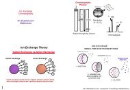
Wash Solvent description<br />
There are two wash solvents<br />
— Strong Needle Wash<br />
o Tubing flushing<br />
o Elimination of components injected<br />
o Never injected<br />
— Weak Needle Wash<br />
o Strong solvent elimination<br />
o Injected with the sample in partial loop pressure assist mode<br />
Dr. Shula Levin, Medtechnica<br />
Wash cycle after injection<br />
needle<br />
VDD<br />
Sample Syringe<br />
BSM<br />
loop<br />
Wash block<br />
to column and<br />
detector<br />
Possible contaminated<br />
area<br />
VDD<br />
Sample Syringe<br />
Wash Solvent Considerations<br />
BSM<br />
loop<br />
to column and<br />
detector<br />
Strong needle wash<br />
followed by weak needle<br />
wash<br />
As a general principle, strong and weak solvents should include the<br />
same organic species<br />
— This may not always be practicable, especially in the case of “sticky”<br />
samples. You may, however use a 100% organic strong wash solvent<br />
Do not use salt buffers in wash solvents<br />
Wash volume ratio (weak to strong)<br />
— Should be about 3:1, weak wash to strong<br />
— Sufficient to ensure the weak wash flushes the strong from the needle<br />
and sample loop<br />
For more details on solvents, see the section titled “Selecting weak<br />
wash and strong wash solvents” in the ACQUITY Operators Guide
6<br />
Strong Wash Solvent<br />
Preparing to Run <strong>UPLC</strong>; Injection and Detection Paramters<br />
Flushes internal and external portion of the needle to prevent<br />
carryover<br />
Typically stronger than sample and mobile phase to dissolve<br />
sample residue<br />
Function performed in the wash station<br />
Strong solvent should be no stronger than the concentration<br />
needed to reduce carryover to an acceptable level<br />
Strong wash solvent does not contact the sample<br />
Weak Wash Solvent<br />
Purges needle and syringe fluid path<br />
Must be compatible with sample solvent<br />
For best results, weak wash solvent should be equivalent to<br />
the following (excluding buffers):<br />
— mobile phase composition (for isocratic separations)<br />
— initial gradient condition (for gradient separations)<br />
— If you dilute the samples, match the weak wash solvent to the<br />
sample diluent<br />
Degassed for good hydraulic properties<br />
Dr. Shula Levin, Medtechnica<br />
Strong Wash Solvent<br />
Choose based on the chemistry application<br />
100% organic solvent is acceptable<br />
— Except THF<br />
— Do not add acid or base in 100% organic solvent<br />
Prime using the needle wash function<br />
Default value is 200 µL<br />
— 200 µL is a typical value for this function<br />
Weak Wash Solvent<br />
Compatible with initial gradient conditions and sample<br />
solubility<br />
Avoid buffers<br />
— increases the risks of precipitation at re-equilibration<br />
Five prime cycles fully replace wash solvents<br />
Default value is 200 µL
7<br />
THREE injection methods available:<br />
Preparing to Run <strong>UPLC</strong>; Injection and Detection Paramters<br />
ACQUITY <strong>UPLC</strong> Sample Manager<br />
Injection Methods<br />
1. Full Loop Injection Method/Mode as the injection technique using<br />
“Pressure Assist”<br />
o Injects 100% of actual loop volume<br />
2. Partial Loop Injection Method/Mode using “Needle Overfill” as the<br />
injection technique<br />
o Selectable: Recommended from 10% to 75% of total loop volume<br />
3. Partial Loop Injection Method/Mode using “Pressure Assist” as the<br />
injection technique<br />
o Selectable: Recommended from 10% to 50% of total loop volume<br />
Full Loop Injection<br />
Step 1 – Aspirate sample and air gap<br />
Dr. Shula Levin, Medtechnica<br />
Full Loop Injection<br />
Example of a 20 µL injection with a 4X overfill<br />
20 µL Sample<br />
Weak Wash<br />
Solvent<br />
Air Gap<br />
Sample<br />
Sample<br />
Weak Wash<br />
Solvent<br />
Air Gap<br />
30 µL<br />
sample<br />
volume<br />
Sample Loop<br />
Volume Injected<br />
Overfill Factor 1 to 4<br />
30 µL<br />
sample<br />
volume<br />
Full Loop Injection<br />
Step 2 – Pressurize and position sample in valve
8<br />
Preparing to Run <strong>UPLC</strong>; Injection and Detection Paramters<br />
Full Loop Injection<br />
Step 3 – Position sample and overfill the loop<br />
Sample Loop contains only sample<br />
No Air Gaps<br />
No weak wash<br />
Summary of Full Loop injection mode<br />
Best accuracy and precision performance<br />
Needs multiple loop volumes of additional sample to be used per<br />
injection<br />
Larger overfill factors are required for smaller loops<br />
Need to change injection loops to vary volume<br />
Dr. Shula Levin, Medtechnica<br />
Full Loop Injection<br />
Step 4 – Sample Injection<br />
Summary of Full Loop<br />
Injection Mode<br />
BENEFITS<br />
— Best accuracy and precision performance<br />
TRADEOFF<br />
— Needs multiple loop volumes of additional sample to be used per<br />
injection<br />
o larger overfill factors are required for smaller loops (buffer zone<br />
improvement)<br />
— Need to change injection loops to vary volume
9<br />
Partial Loop Injection<br />
Weak Wash<br />
Solvent<br />
Preparing to Run <strong>UPLC</strong>; Injection and Detection Paramters<br />
Sample<br />
Air Gap<br />
Sample Loop<br />
Volume Injected<br />
Pressure Assist Injection Sequence<br />
Step 1 – Aspirate sample and air gap<br />
Weak Wash<br />
Solvent<br />
Dr. Shula Levin, Medtechnica<br />
Partial Loop (Pressure Assist)<br />
Loop Volume (µL) Needle Overfill<br />
1 Not Recommended<br />
2 Not Recommended<br />
5 Not Recommended<br />
10 1.0 – 5.0<br />
20 2.0 – 10.0<br />
50 5.0 – 25.0<br />
Pressure Assist Injection Sequence<br />
Step 2 – Pressurize and position sample in valve
10<br />
Preparing to Run <strong>UPLC</strong>; Injection and Detection Paramters<br />
Pressure Assist Injection Sequence<br />
Step 3 – Position the sample<br />
Summary of Partial Loop<br />
using Pressure Assist<br />
Shorter Cycle Time than PLUNO<br />
No sample cushion<br />
Sample volume is conserved<br />
Recommended for large sample loop injections<br />
Performance dependency on weak wash solvent matching to mobile<br />
phase<br />
Air Gaps injected onto Column<br />
Accuracy is generally lower compared to Needle Overfill<br />
Has lower injection range, within a given loop for partial loop<br />
injections. Injection range is from 10 – 50% of the loop volume<br />
Accuracy and Precision are lower than Full Loop Mode<br />
Dr. Shula Levin, Medtechnica<br />
Pressure Assist Injection Sequence<br />
Step 4 – Injection valve injects sample<br />
Sample Loop contains<br />
Sample, air gaps and weak wash<br />
Partial Loop Using Needle Overfill
11<br />
Summary of Partial Loop<br />
using Pressure Assist<br />
BENEFITS:<br />
— Short Cycle Time<br />
Preparing to Run <strong>UPLC</strong>; Injection and Detection Paramters<br />
— Sample volume is conserved<br />
— Recommended for large sample loop injections<br />
TRADEOFF:<br />
— Accuracy and Precision are lower than Full Loop Mode<br />
— Performance dependency on weak wash solvent matching to mobile<br />
phase<br />
— Accuracy is generally lower compared to Needle Overfill<br />
Partial Loop using Needle Overfill<br />
Step 1– Aspirate Sample and Air Gap<br />
Dr. Shula Levin, Medtechnica<br />
Partial Loop Using Needle Overfill<br />
Partial Loop using Needle Overfill<br />
Step 2 – Injection Sequence
12<br />
Preparing to Run <strong>UPLC</strong>; Injection and Detection Paramters<br />
Partial Loop using Needle Overfill<br />
Step 3 – Injection Sequence<br />
Partial Loop using Needle Overfill<br />
Step 5 – Injection Sequence<br />
Dr. Shula Levin, Medtechnica<br />
Partial Loop using Needle Overfill<br />
Step 4 – Injection Sequence<br />
Partial Loop using Needle Overfill<br />
Step 1– Aspirate Sample and Air Gap
13<br />
Preparing to Run <strong>UPLC</strong>; Injection and Detection Paramters<br />
Partial Loop using Needle Overfill<br />
Step 2 – Injection Sequence<br />
Partial Loop using Needle Overfill<br />
Step 4 – Injection Sequence<br />
Dr. Shula Levin, Medtechnica<br />
Partial Loop using Needle Overfill<br />
Step 3 – Injection Sequence<br />
Partial Loop using Needle Overfill<br />
Step 5 – Injection Sequence
14<br />
Preparing to Run <strong>UPLC</strong>; Injection and Detection Paramters<br />
Summary of Partial Loop<br />
using Needle Overfill<br />
No weak wash injected onto column<br />
— mobile phase and sample injected<br />
Air gap not injected on column<br />
Sample does not come into contact with weak wash<br />
Recommended for partial loop injections, especially from small<br />
loops because accuracy is improved compared to Pressure Assist<br />
Partial loop injections<br />
Has wider linear range, can inject from 10 – 75% of the loop<br />
volume<br />
Cycle time depending on aspiration rate (with smaller loops the<br />
time increases)<br />
Needs 15 µL additional sample to be used for cushion volume per<br />
injection irregardless of injection size<br />
Accuracy and precision lower than full loop mode<br />
Injection Air Gap<br />
Automatic or manual<br />
Full loop or partial loop injection<br />
— Critical for partial loop injection<br />
Full loop<br />
Dr. Shula Levin, Medtechnica<br />
— Air gap<br />
Manual settings<br />
(need to be set)<br />
Injection Parameters<br />
Injection Parameters<br />
Automatic settings<br />
(already set in the software<br />
See HELP)<br />
Good Repeatability:<br />
Setting Up the Sample Manager<br />
o 4 µL for 30 µL needle<br />
o 2 µL for 15 µL needle<br />
— Overfill factor depends on loop size<br />
o see Help for Automatic parameters<br />
— Metering device compatible with sample volume<br />
Partial loop<br />
— Low draw speed for low volume<br />
— Pre and post air gap are essential<br />
— Automatic parameters<br />
o Pre and post air gap of 1 µL<br />
o 100 µL per minute
15<br />
Strong Contaminations<br />
Preparing to Run <strong>UPLC</strong>; Injection and Detection Paramters<br />
If the system is contaminated, some spare parts must be<br />
changed<br />
— Why:<br />
Air Gap<br />
o Due to previous bad or not appropriate washing, contamination<br />
has been accumulated and then released since the system is not<br />
able to compensate anymore<br />
o Manual washing is not strong enough to eliminate carry-over<br />
— How: Which spare parts must be changed<br />
o Seal wash of the wash station<br />
o Needle<br />
o VDD (bubble detector)<br />
o Loop<br />
Question:<br />
— 1) Should I use air gap?<br />
o Yes or No?<br />
o Which one?<br />
• Pre air, post air or both?<br />
— 2) What volume?<br />
Question:<br />
— Should I use?<br />
o Full loop<br />
o Partial loop injection<br />
Dr. Shula Levin, Medtechnica<br />
Strong Washing<br />
Main Parameters Summary<br />
— Strong solvent 200 µL<br />
Weak Wash<br />
— Weak solvent 600 µL<br />
Full loop or partial loop injection<br />
— Use automatic settings<br />
Air gap<br />
— For partial injection<br />
— Automatic<br />
Draw speed<br />
— Automatic<br />
Pre and Post Air Gap Influence: Example<br />
4 4 1 140787 132577 96240 57406 136252 95577 45260 16142<br />
0 0 1 90362 85040 62005 42553 92886 64077 30046 12199<br />
Diffusion effect 55.80% 55.90% 55.21% 34.90% 46.69% 49.16% 50.64% 32.32%<br />
4 4 1 140787 132577 96240 57406 136252 95577 45260 16142<br />
0 4 1 89291 84372 63720 40764 85074 61209 29754 11578<br />
Diffusion effect 57.67% 57.13% 51.04% 40.83% 60.16% 56.15% 52.11% 39.42%<br />
4 4 1 140787 132577 96240 57406 136252 95577 45260 16142<br />
4 0 1 120864 113953 81763 52170 122771 85128 39046 14816<br />
Diffusion effect<br />
16.48% 16.34% 17.71% 10.04% 10.98% 12.27% 15.91% 8.95%
16<br />
Air Gap Effects<br />
Preparing to Run <strong>UPLC</strong>; Injection and Detection Paramters<br />
pre – air gap is more critical than post – air gap<br />
automatic<br />
Pre air gap Post air gap Peak area Peak height % area difference<br />
Automatic (1) Automatic (1) 38889 27156<br />
0,0<br />
4 0 38488 26796 98.97<br />
4 4 38179 26592 98.17<br />
0 4 30866 21404 79.37<br />
0 0 30748 21413 79.07<br />
Air Gap Settings<br />
Automatic settings<br />
— Pre and post air gap<br />
— 4 µL each<br />
— 1 µL for PLUNO<br />
Manual settings<br />
— Lower values:<br />
0,4<br />
o Sample diffusion providing peak area and peak height reduction<br />
— Higher values:<br />
o Can effect the chromatogram<br />
• Higher peak height RSD<br />
• Loss of resolution<br />
4,4<br />
4,0<br />
Air Gap<br />
Dr. Shula Levin, Medtechnica<br />
Large air gap volume can effect the chromatogram.<br />
Detection Mechanisms<br />
System Configuration<br />
Detector Designs<br />
Importance of Sampling Rate<br />
Detector Requirements
17<br />
Preparing to Run <strong>UPLC</strong>; Injection and Detection Paramters<br />
Designing for <strong>UPLC</strong><br />
ACQUITY <strong>UPLC</strong> columns produce small volume peaks<br />
To avoid band spreading and maintain concentration the flow cell<br />
volume must be corresponding low<br />
If you use conventional flow cells the path length must be reduced<br />
which results in a loss of sensitivity<br />
<strong>UPLC</strong> detection requires cells that are designed for minimal<br />
dispersion, low cell volumes and optimum light throughput<br />
Importance of Sampling Rate<br />
Must ensure enough points are collected across a peak to<br />
adequately define the peak shape: 20-50 points across the<br />
peak.<br />
Peak detection algorithms require a minimum number of points<br />
across a peak to distinguish it from baseline noise and correctly<br />
determine peak lift off and touch down<br />
A peak which does not have enough data points will be difficult to<br />
integrate and therefore have irreproducible peak areas and<br />
heights.<br />
Dr. Shula Levin, Medtechnica<br />
ACQUITY <strong>UPLC</strong> TUV and PDA<br />
– Features<br />
Light guided flow cell design<br />
Two flow cell options<br />
Low noise electronics<br />
— High brightness lamp<br />
Support for data rates up to 80 Hz<br />
— Independent data rate and filter constants<br />
Console Control<br />
Effect of Sampling Rate on Chromatography –<br />
TUV<br />
AU<br />
0.080<br />
0.070<br />
0.060<br />
0.050<br />
0.040<br />
0.030<br />
0.020<br />
0.010<br />
0.000<br />
1 pt/s<br />
5 pts/s<br />
40 pts/s<br />
0.50 0.52 0.54 0.56 0.58 0.60 0.62<br />
Minutes<br />
0.64 0.66 0.68 0.70 0.72 0.74
18<br />
Preparing to Run <strong>UPLC</strong>; Injection and Detection Paramters<br />
Effect of Sampling Rate on Reproducibility<br />
Sampling<br />
Rate<br />
Points<br />
Across<br />
Peak<br />
Peak<br />
Area<br />
Peak Area<br />
%RSD<br />
Peak<br />
Height<br />
Peak<br />
Height<br />
%RSD<br />
1 pt/s 2 44125 2.436 27451 15.515<br />
2 pts/s 4 32822 1.790 41207 13.455<br />
5 pts/s 7 31554 0.971 67355 3.962<br />
10 pts/s 13 31321 1.129 73638 1.015<br />
20 pts/s 25 31284 0.603 76001 1.156<br />
40 pts/s 49 31534 0.284 77606 1.127<br />
Measured for Peak #5 - Phenacetin<br />
Filtering Constant At High Data Rates<br />
AU<br />
0.080<br />
0.070<br />
0.060<br />
0.050<br />
0.040<br />
0.030<br />
0.020<br />
0.010<br />
0.000<br />
No Filtering<br />
0.1s<br />
0.3s<br />
0.5s<br />
1.0s<br />
0.50 0.52 0.54 0.56 0.58 0.60 0.62 0.64 0.66 0.68 0.70 0.72 0.74 0.76 0.78 0.80<br />
Minutes<br />
Dr. Shula Levin, Medtechnica<br />
Tunable Ultra Violet Specifications<br />
Wavelength Range 190 – 700 nm<br />
Increased data acquisition rates<br />
— Maximum 80 pts per second in single wavelength mode<br />
— Maximum 2 pts per second in dual wavelength mode<br />
Optimized time constant to filter smaller peak widths<br />
Two flow cells<br />
— Analytical<br />
— High Sensitivity<br />
ACQUITY PDA Detector<br />
Wavelength Range 190 – 500 nm<br />
MassLynx v4.0/4.1<br />
—80 pts/sec maximum data rate<br />
—0, 1, 2, or 3 second time constants<br />
—3D mode only<br />
Empower build 1154/2154<br />
—80 pts/sec maximum data rate<br />
—0.1 – 3.0 seconds- time constants<br />
—2D or 3D Mode<br />
Two flow cells<br />
—Analytical<br />
—High Sensitivity
19<br />
Preparing to Run <strong>UPLC</strong>; Injection and Detection Paramters<br />
Conditions:<br />
Influence of Detector Settings: Sampling Rate<br />
Chromatographic Conditions :<br />
Column: ACQUITY BEH C 18 2.1 x 30 mm, 1.7 µm<br />
Mobile Phase A: 0.1% Formic Acid in H 2O<br />
Mobile Phase B: 0.1% Formic Acid in ACN<br />
Flow Rate: As indicated<br />
Isocratic: 97% A: 3% B<br />
Injection Volume: 2.0 µL<br />
Sample Diluent: 0.2% Formic Acid in water<br />
Strong Needle Wash: 50 µL 50 ACN: 50 H 2O<br />
Weak Needle Wash: 500 µL 0.1% Formic Acid in<br />
H 2O<br />
Temperature: 32°C<br />
Detection: UV @ 280 nm<br />
Time Constant: 0.1<br />
Sampling rate: as indicated<br />
Instrument: <strong>UPLC</strong>: Waters ACQUITY <strong>UPLC</strong>, with<br />
TUV detector<br />
Influence of Detector Settings:<br />
Sampling Rate<br />
Analytes (Caffeine and Metabolites):<br />
1. 1-methylxanthene<br />
2. 1,3-dimethyluric acid<br />
3. Theobromine<br />
4. 1,7-dimethyluric acid<br />
5. 1,7-dimethylxanthene<br />
6. Caffeine<br />
Influence of Sampling Rate on Peak Height<br />
Sampling Rate 40 32 20 10 5 2 1<br />
1-methylxanthene 27145 27284 27525 26815 26694 21370 13530<br />
1,3-dimethyluric acid 41173 41191 41869 41173 41221 36798 26356<br />
theobromine 56726 56624 57589 56673 56578 51930 38274<br />
1,7-dimethyluric acid 25182 25015 25501 24917 25009 23586 20093<br />
1,7-dimethylxanthene 18910 16717 18311 16739 17912 17829 15984<br />
caffeine 14405 14103 14024 14367 13901 14201 13529<br />
Influence of Sampling Rate on Resolution<br />
Sampling Rate<br />
1-methylxanthene<br />
40 32 20 10 5 2 1<br />
1,3-dimethyluric acid 6.9 6.98 6.91 6.96 6.7 5.84 4.79<br />
theobromine 1.9 1.86 1.93 1.87 1.87 1.78 1.44<br />
1,7-dimethyluric acid 7.81 7.75 7.71 7.84 7.67 7.23 6.73<br />
1,7-dimethylxanthene 2.36 2.29 2.36 2.42 2.37 2.43 2.09<br />
caffeine 16.29 16.39 16.27 16.14 16.24 15.98 15.5<br />
Dr. Shula Levin, Medtechnica<br />
Influence of Detector Settings:<br />
Sampling Rate<br />
AU<br />
AU<br />
AU<br />
0.05<br />
0.00<br />
0.05<br />
0.00<br />
0.05<br />
0.00<br />
0.00 0.50 1.00 1.50 2.00 2.50 3.00 3.50 4.00 4.50<br />
Minutes<br />
0.00 0.50 1.00 1.50 2.00 2.50 3.00 3.50 4.00 4.50<br />
Minutes<br />
Conditions:<br />
Influence of Detector Settings: Time Constant<br />
40 Hz<br />
5 Hz<br />
1 Hz<br />
Chromatographic Conditions :<br />
Analytes (Caffeine and Metabolites):<br />
Column: ACQUITY BEH C18 2.1 x 30 mm, 1.7 µm 1. 1-methylxanthene<br />
Mobile Phase A: 0.1% Formic Acid in H2O 2. 1,3-dimethyluric acid<br />
Mobile Phase B: 0.1% Formic Acid in ACN<br />
3. Theobromine<br />
Flow Rate: As indicated<br />
4. 1,7-dimethyluric acid<br />
Isocratic: 97% A : 3% B<br />
Injection Volume: 2.0 µL<br />
Sample Diluent: 0.2% Formic Acid in water<br />
Strong Needle Wash: 50 µL 50 ACN : 50 H2O Weak Needle Wash: 500 µL 0.1% Formic Acid in<br />
H2O Temperature: 32°C<br />
Detection: UV @ 280 nm<br />
Time Constant: as indicated<br />
Sampling rate: 20 pts/sec<br />
Instrument: <strong>UPLC</strong>: Waters ACQUITY <strong>UPLC</strong>, with<br />
TUV detector<br />
5.<br />
6.<br />
1,7-dimethylxanthene<br />
Caffeine
20<br />
AU<br />
AU<br />
AU<br />
0.05<br />
0.00<br />
0.05<br />
0.00<br />
0.05<br />
0.00<br />
Preparing to Run <strong>UPLC</strong>; Injection and Detection Paramters<br />
Influence of Detector Settings:<br />
Time Constant<br />
0.00 1.00 2.00 3.00 4.00<br />
Minutes<br />
Resolution/Low Dispersion Flow Cell<br />
A light guiding flow cell is<br />
essentially an optical fiber<br />
whose core material is a fluid<br />
The optical fiber consists of a<br />
core material surrounded by a<br />
cladding layer (Teflon AF).<br />
Light is guided through the core<br />
by the process of total internal<br />
reflection;<br />
— light rays that encounter the<br />
interface between the core and<br />
cladding are reflected back into<br />
the core with essentially 100%<br />
efficiency<br />
Light Path<br />
α Mobile Phase<br />
T c = 0<br />
T c = 1.5<br />
T c = 2.5<br />
TeflonAF<br />
TeflonAF<br />
Dr. Shula Levin, Medtechnica<br />
Influence of Detector Settings:<br />
Time Constant<br />
Influence of Time Constant on Peak Height<br />
Time Constant 0 0.1 0.5 1 1.5 2 2.5<br />
1-methylxanthene 27525 26592 19732 13094 9615 7475 5923<br />
1,3-dimethyluric acid 41869 40811 33662 24129 18370 14791 15241<br />
Theobromine 57589 56123 47629 35066 27099 21813 18653<br />
1,7-dimethyluric acid 25501 25121 23014 18704 15325 12503 10522<br />
1,7-dimethylxanthene 18311 18916 17631 14724 12382 10126 8674<br />
Caffeine 14024 14069 14253 13456 13057 12445 11338<br />
Influence of Time Constant on Resolution<br />
Time Constant 0 0.1 0.5 1 1.5 2 2.5<br />
1-methylxanthene<br />
1,3-dimethyluric acid 6.91 6.64 5.24 3.53<br />
Theobromine 1.93 1.87 1.53 1.08<br />
1,7-dimethyluric acid 7.71 7.58 6.79 5.19 3.68<br />
1,7-dimethylxanthene 2.36 2.37 2.18 1.8 1.45 1.22 1.02<br />
Caffeine 16.27 16.5 16.19 15.09 13.47 12.18 10.87<br />
Zooming In<br />
Mechanism of Total Internal Reflectance<br />
— The TIR condition requires that a component of the incident wave<br />
penetrates the AF, typically to a small fraction of the wavelength of<br />
incident light.<br />
90-α<br />
Teflon ® AF, n(w)<br />
Mobile Phase, n(f)
21<br />
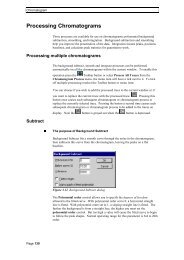
Teflon ® AF light guiding<br />
flow cells may, with time,<br />
develop absorbance<br />
baselines that exhibit<br />
curvature.<br />
This is attributed to<br />
changes in optical<br />
characteristics of AF<br />
surface due to<br />
contaminants.<br />
These “changes” effect TIR<br />
efficiency.<br />
Preparing to Run <strong>UPLC</strong>; Injection and Detection Paramters<br />
Why is Flow Cell<br />
Maintenance Important?<br />
Light Guided Flow Cell Maintenance<br />
Prevent build-up of contaminants:<br />
—Always maintain fluid flow through the cell<br />
o Avoid “Lamp ON - Flow OFF” condition<br />
0.2<br />
0.15<br />
0.1<br />
0.05<br />
o Make clean connections to cell<br />
—Flush new columns<br />
Dormant cells<br />
0<br />
06-Oct-2005 11:09:15 grd s wp1114.arw<br />
-0.05<br />
0 0.5 1 1.5 2 2.5 3 3.5 4<br />
Example of baseline curvature. The top plot is a chromatogram of a<br />
gradient separation. The bottom plot is zoomed vertically to show<br />
more clearly the magnitude of the baseline curvature.<br />
—Pre-flush with clean mobile phase, dry with clean air purge, then<br />
plug ports<br />
Certain low strength, acid-based, wash solutions can help<br />
reduce baseline curvature if contamination occurs<br />
—Example – 1% weak concentration formic acid solution<br />
Dr. Shula Levin, Medtechnica<br />
The Median Baseline Filter (MBF)<br />
— A processing tool for alleviating baseline curvature<br />
MBF Off<br />
MBF On<br />
— The MBF operates during acquisition in real time on the chromatogram<br />
whose baseline is to be corrected.<br />
— The MBF automatically extracts the baseline, smoothes it, and then<br />
subtracts the smoothed baseline from the original chromatogram.<br />
— Result is a chromatogram with greatly reduced baseline curvature.<br />
TUV Flow Cells<br />
High Sensitivity<br />
25 mm Pathlength<br />
2400 nL Volume<br />
Analytical<br />
10 mm Pathlength<br />
500 nL Volume
22<br />
AU<br />
ACQUITY PDA<br />
Flow Cell Options<br />
Preparing to Run <strong>UPLC</strong>; Injection and Detection Paramters<br />
High Sensitivity Analytical<br />
25 mm Pathlength<br />
2400 nL Volume<br />
Flow Cell Signal Comparison<br />
0.0060<br />
0.0055<br />
0.0050<br />
0.0045<br />
0.0040<br />
0.0035<br />
0.0030<br />
0.0025<br />
0.0020<br />
0.0015<br />
0.0010<br />
0.0005<br />
0.0000<br />
10 mm Pathlength<br />
500 nL Volume<br />
Analytical High Sensitivity Ratio<br />
Area 2995 6845 2.29<br />
Height 2368 5123 2.16<br />
Peak Width at 13.4% 2.02 sec 2.14 sec 1.059<br />
Noise:<br />
High Sensitivity Flow Cell = 0.000015 AU<br />
Analytical Flow Cell = 0.000012 AU<br />
0.30 0.40 0.50 0.60 0.70 0.80 0.90 1.00<br />
Minutes<br />
1.10 1.20 1.30 1.40 1.50 1.60 1.70<br />
Dr. Shula Levin, Medtechnica<br />
Flow Cell Comparison<br />
<strong>UPLC</strong> Conditions<br />
System: ACQUITY <strong>UPLC</strong> with TUV<br />
Column: 2.1 X 50 mm ACQUITY <strong>UPLC</strong> BEH C18, 1.7 µm<br />
Mobile Phase 7:3 Water/ACN + 0.1% Formic<br />
Flow Rate: 0.65 mL/min<br />
Injection Volume: 2 µL<br />
Strong Wash = 75% ACN/25% Water (250 uL)<br />
Weak Wash = 5% ACN/95%Water (1000 uL)<br />
Sample Temperature: 10 °C<br />
Column Temperature: 35 °C<br />
Detection: ACQUITY TUV @ 231nm (0-1.7 min)<br />
280 nm (1.7 – 3.0 min) 20 pps, FTC=0.30<br />
Sample = 080 mg/mL2,4-D in 50% ACN/50% Water<br />
Data: Empower 2<br />
2,4-D and Impurities<br />
AU<br />
0.20<br />
0.18<br />
0.16<br />
0.14<br />
0.12<br />
0.10<br />
0.08<br />
0.06<br />
0.04<br />
0.02<br />
0.00<br />
Analytical Flow Cell<br />
Flow Cell Comparison – Sensitivity<br />
Area<br />
Height<br />
Peak Width at 13.4%<br />
Analytical<br />
140955<br />
93942<br />
0.040497<br />
High Sensitivity<br />
326881<br />
211138<br />
0.042033<br />
Delta<br />
2.319<br />
2.248<br />
1.038<br />
High Sensitivity Flow Cell<br />
4.40 4.45 4.50 4.55 4.60 4.65<br />
Minutes<br />
4.70 4.75 4.80 4.85 4.90<br />
AU<br />
0.24<br />
0.22<br />
0.20<br />
0.18<br />
0.16<br />
0.14<br />
0.12<br />
0.10<br />
0.08<br />
0.06<br />
0.04<br />
0.02<br />
0.00<br />
-0.02<br />
-0.04<br />
-0.06<br />
0.00 1.00 2.00 3.00 4.00 5.00 6.00 7.00 8.00 9 .00<br />
Minutes
23<br />
Preparing to Run <strong>UPLC</strong>; Injection and Detection Paramters<br />
Flow Cell Recommendations<br />
Analytical Flow Cell<br />
— Better chromatographic resolution<br />
High Sensitivity Flow Cell<br />
— For the highest sensitivity<br />
— Higher peak height (Beer’s law)<br />
— In general, better signal to noise<br />
Both Cells<br />
o Slightly higher noise because more flow perturbations to contribute to<br />
the noise, especially with absorbing mobile phases<br />
— Same linearity<br />
— Cover the full flow rate range<br />
Back Pressure Regulator<br />
Maintains a constant 250 psi<br />
back pressure on the flow cell<br />
Not used with a mass<br />
spectrometer<br />
Used with both TUV and PDA<br />
Dr. Shula Levin, Medtechnica<br />
ACQUITY <strong>UPLC</strong><br />
High Brightness Lamp<br />
High brightness deuterium lamp<br />
—Low noise characteristics<br />
—Nearly twice the brightness (energy) of ordinary deuterium<br />
lamps<br />
Benefits<br />
—Less Noise<br />
—Higher sensitivity<br />
Lamp Warranty<br />
— 2000 hours<br />
Lamp Firmware through Console<br />
—Hours of operation<br />
—Ignitions<br />
—Serial Number<br />
Recommendations
24<br />
Data acquisition<br />
Preparing to Run <strong>UPLC</strong>; Injection and Detection Paramters<br />
Recommendations<br />
— Sampling rate<br />
— Filtering<br />
Tubing<br />
Vial Storage<br />
o Time constant<br />
— Use only the internal diameters for the<br />
ACQUITY <strong>UPLC</strong> system<br />
— Use connections with features designed for<br />
the ACQUITY <strong>UPLC</strong> system<br />
Bad storage could induce possible<br />
contamination<br />
—Ghost peaks<br />
—Unpredictable phenomena<br />
Storage condition<br />
—With cap<br />
—Away from dust<br />
Dr. Shula Levin, Medtechnica<br />
Sources of Potential Contaminants<br />
Incompletely flushed samples, in stagnant condition<br />
—Formation of particulates<br />
—Formation of “thin film” layer<br />
—Photodegradation<br />
Column bleed, connection, tubing…<br />
Observations/Results<br />
—Progressive increase in gradient baseline curvature<br />
—Decrease in absolute energy (increased exposure time)<br />
Injections Recommendations<br />
Wash Process<br />
— Dedicated to sample to decrease carry over<br />
Full loop injection<br />
— Use overfill factor<br />
Partial loop injection<br />
— Use air gaps<br />
Air gap and Draw speed<br />
— Use automatic settings<br />
Sample loop volume determination<br />
— Best way to load the sample correctly in the loop