Case Study of an Innovative HVAC System with Integral Dehumidifier
Case Study of an Innovative HVAC System with Integral Dehumidifier
Case Study of an Innovative HVAC System with Integral Dehumidifier

Create successful ePaper yourself
Turn your PDF publications into a flip-book with our unique Google optimized e-Paper software.
supply air f<strong>an</strong> motor (ECM) was desirable to<br />
deliver <strong>an</strong> appropriate supply air flow rate for the<br />
prototype air h<strong>an</strong>dler as necessary. An air<br />
h<strong>an</strong>dler <strong>with</strong> a sl<strong>an</strong>t coil configuration was<br />
preferred to allow room <strong>with</strong>in the cabinet for<br />
installation <strong>of</strong> the dehumidifier’s compressor,<br />
condenser coil, <strong>an</strong>d f<strong>an</strong> assembly. The<br />
criteria used to select the st<strong>an</strong>dalone room air<br />
dehumidifier was that it have a dehumidification<br />
capacity greater th<strong>an</strong> or equal to 37 pints/day as<br />
determined in the previous simulation study.<br />
A nominal 3-ton air h<strong>an</strong>dler <strong>an</strong>d a 50-pint per<br />
day room air dehumidifier were purchased <strong>an</strong>d<br />
disassembled for inspection. Both systems used<br />
R-22 vapor compression refrigeration equipment<br />
to cool <strong>an</strong>d/or dehumidify <strong>an</strong> air stream. The<br />
prototype air conditioner/dehumidification<br />
system integrated portions <strong>of</strong> the room<br />
dehumidifier into the air h<strong>an</strong>dler cabinet while<br />
maintaining independent control for each system.<br />
The existing sl<strong>an</strong>ted evaporator coil was recircuited,<br />
<strong>with</strong> the upper portion (using 5 <strong>of</strong> the 6<br />
original circuits) being devoted to the<br />
conventional direct-exp<strong>an</strong>sion cooling system<br />
<strong>an</strong>d the independent lower portion <strong>of</strong> the coil<br />
devoted to being the evaporator coil for the<br />
dehumidifier. The dehumidifier’s condenser coil<br />
was installed directly above its evaporator coil in<br />
the direction <strong>of</strong> air flow, <strong>an</strong>d a dedicated<br />
dehumidifier f<strong>an</strong> was used to draw air through<br />
these heat exch<strong>an</strong>gers using a rect<strong>an</strong>gular air<br />
plenum mounted on top <strong>of</strong> the dehumidifier’s<br />
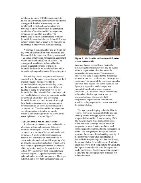
condenser coil. The dehumidifier’s compressor<br />
was also mounted <strong>with</strong>in the air h<strong>an</strong>dler<br />
cabinet’s heat exch<strong>an</strong>ger frame as shown in the<br />
lower right-h<strong>an</strong>d corner <strong>of</strong> Figure 2.<br />
LABORATORY MEASUREMENTS<br />
Steady-state perform<strong>an</strong>ce was evaluated in a<br />
laboratory setting <strong>an</strong>d measured data were<br />
compiled for <strong>an</strong>alysis. Over 80 tests were<br />
conducted at a variety <strong>of</strong> indoor <strong>an</strong>d outdoor air<br />
conditions. A multivariate linear regression<br />
<strong>an</strong>alysis was performed on measured data to<br />
characterize the total <strong>an</strong>d sensible capacity <strong>of</strong> the<br />
air-conditioning/dehumidification system over a<br />
wide r<strong>an</strong>ge <strong>of</strong> operating conditions. The results<br />
<strong>of</strong> the regression <strong>an</strong>alysis for a particular set <strong>of</strong><br />
tests at 95ºF outdoor dry-bulb temperature are<br />
shown in Figure 3. Capacity is plotted versus<br />
indoor chamber wet-bulb temperature. The target<br />
indoor chamber wet-bulb temperature are also<br />
Figure 2. Air H<strong>an</strong>dler <strong>with</strong> dehumidification<br />
system components<br />
shown as dashed vertical lines. Notice the<br />
measured data (symbols) do not line up exactly<br />
<strong>with</strong> the target indoor chamber wet-bulb<br />
temperature in m<strong>an</strong>y cases. The regression<br />
<strong>an</strong>alysis was used to adjust for the differences<br />
between actual test conditions <strong>an</strong>d the target test<br />
conditions. The output <strong>of</strong> the regression model is<br />
shown as a red dashed line in the figure. In this<br />
figure, the regression model output was<br />
calculated based on the actual operating<br />
conditions (i.e., measured indoor chamber drybulb<br />
<strong>an</strong>d wet-bulb temperatures, <strong>an</strong>d the<br />
measured outdoor chamber dry-bulb<br />
temperature) to predict both the total <strong>an</strong>d<br />
sensible cooling capacity for comparison <strong>with</strong><br />
the measured data.<br />
The top, upward-sloping red dashed line in<br />
Figure 3 represents the predicted total cooling<br />
capacity for the prototype system when the<br />
integrated dehumidifier is not operating (AC).<br />
The measured data (blue diamonds) line up<br />
rather well <strong>with</strong> the target indoor wet-bulb<br />
temperatures, as well as the predicted total<br />
cooling capacity determined using the regression<br />
model. The next group <strong>of</strong> data (aqua circles)<br />
represent the measured total cooling capacity <strong>of</strong><br />
the prototype system when the integrated<br />
dehumidifier is operating (ACDH). In this case,<br />
the measured data do not align as well <strong>with</strong> the<br />
target indoor wet-bulb temperature; however, the<br />
data agree extremely well <strong>with</strong> the regression<br />
model predictions. In either case, total capacity<br />
is shown to be a strong function <strong>of</strong> indoor wetbulb<br />
temperature.