1400W Mitre Saw 01 - Free-Instruction-Manuals.com
1400W Mitre Saw 01 - Free-Instruction-Manuals.com
1400W Mitre Saw 01 - Free-Instruction-Manuals.com

You also want an ePaper? Increase the reach of your titles
YUMPU automatically turns print PDFs into web optimized ePapers that Google loves.
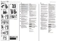
Fig.13<br />
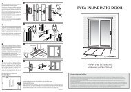
Fig.14<br />
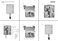
Fig.15<br />
g1<br />
g2<br />
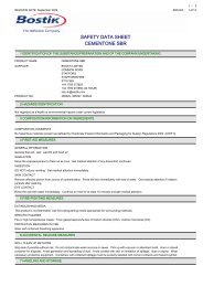
Fig.16<br />
Fig.17<br />
d<br />
d<br />
d<br />
e<br />
f1<br />
f2<br />
wrenches have been removed and that all screws,<br />
bolts and other fittings are securely tightened.<br />
There are no user serviceable parts in your power<br />
tool. Never use water or chemical cleaners to<br />
clean your power tool. Wipe clean with a dry cloth.<br />
Always store your power tool in a dry place. Keep<br />
the motor ventilation slots clean. Keep all working<br />
controls free of dust. Occasionally you may see<br />
sparks through the ventilation slots. This is normal<br />
and will not damage your power tool.<br />
If the supply cord of this power tool is damaged, it<br />
must be replaced by a specially prepared cord<br />
available through the service organization.<br />
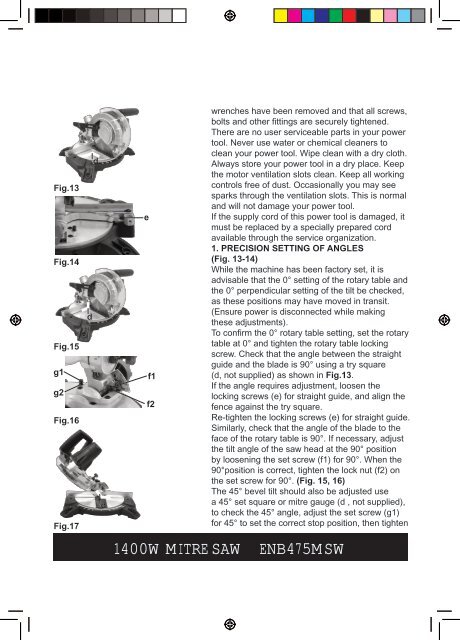
1. PRECISION SETTING OF ANGLES<br />
(Fig. 13-14)<br />
While the machine has been factory set, it is<br />
advisable that the 0° setting of the rotary table and<br />
the 0° perpendicular setting of the tilt be checked,<br />
as these positions may have moved in transit.<br />
(Ensure power is disconnected while making<br />
these adjustments).<br />
To confirm the 0° rotary table setting, set the rotary<br />
table at 0° and tighten the rotary table locking<br />
screw. Check that the angle between the straight<br />
guide and the blade is 90° using a try square<br />
(d, not supplied) as shown in Fig.13.<br />
If the angle requires adjustment, loosen the<br />
locking screws (e) for straight guide, and align the<br />
fence against the try square.<br />
Re-tighten the locking screws (e) for straight guide.<br />
Similarly, check that the angle of the blade to the<br />
face of the rotary table is 90°. If necessary, adjust<br />
the tilt angle of the saw head at the 90° position<br />
by loosening the set screw (f1) for 90°. When the<br />
90°position is correct, tighten the lock nut (f2) on<br />
the set screw for 90°. (Fig. 15, 16)<br />
The 45° bevel tilt should also be adjusted use<br />
a 45° set square or mitre gauge (d , not supplied),<br />
to check the 45° angle, adjust the set screw (g1)<br />
for 45° to set the correct stop position, then tighten<br />
<strong>1400W</strong> MITRE SAW ENB475MSW