Installation instructions Toyota Corolla - Funkwerk Dabendorf GmbH
Installation instructions Toyota Corolla - Funkwerk Dabendorf GmbH
Installation instructions Toyota Corolla - Funkwerk Dabendorf GmbH

Create successful ePaper yourself
Turn your PDF publications into a flip-book with our unique Google optimized e-Paper software.
128 8224 1.02<br />
GB English<br />
<strong>Installation</strong> <strong>instructions</strong><br />
<strong>Toyota</strong> <strong>Corolla</strong><br />
(Built from 2007)
Table of contents<br />
1 Introduction / Preface ................................................................... 3<br />
2 Safety Instructions ...................................................................... 4<br />
3 Conformity statement ................................................................. 5<br />
4 Scope of Delivery / Package content ........................................... 6<br />
5 <strong>Installation</strong> <strong>instructions</strong> .............................................................. 7<br />
5.1 Preparation ............................................................................................ 7<br />
5.2 <strong>Installation</strong> locations ............................................................................. 7<br />
5.2.1 Checking cable lengths ................................................................................................ 7<br />
5.2.2 Selection of the installation location for the electronics box ...................................... 7<br />
5.2.3 Selection of the point of installation for the microphone ............................................ 8<br />
5.3 Mounting Components ........................................................................... 9<br />
5.3.1 Mounting the electronics box ....................................................................................... 9<br />
5.3.2 Mounting the microphone ............................................................................................ 9<br />
5.4 Connection Concept ............................................................................... 10<br />
5.5 <strong>Installation</strong> of the components .............................................................. 10<br />
5.6 Functional Test ...................................................................................... 14<br />
5.7 Symbols ................................................................................................. 14<br />
5.7.1 Key functions ................................................................................................................ 14<br />
5.8 Getting started ....................................................................................... 15<br />
5.8.1 On / Off function ........................................................................................................... 15<br />
5.8.2 Coupling ........................................................................................................................ 15<br />
5.8.3 Automatic coupling ....................................................................................................... 15<br />
5.8.4 LED status .................................................................................................................... 15<br />
6 Troubleshooting .......................................................................... 16<br />
7 Spares and accessories .............................................................. 17<br />
8 Technical specifications .............................................................. 18<br />
9 Certification ................................................................................ 18<br />
10 Hotline ......................................................................................... 19<br />
EGO TS
1<br />
Introduction / Preface<br />
Congratulations on your new EGO!<br />
EGO TS is the intelligent entry-level solution for telephone use in your car: simple to operate,<br />
elegant and compact – with Bluetooth and audio enjoyment too.<br />
The installation of your EGO TS in your car requires specialist knowledge and skills. We recommend<br />
that the installation be carried out in a qualified professional workshop.<br />
Before installation in your car, please make sure that your mobile phone is fully compatible with<br />
EGO TS. If you are uncertain, please consult your dealer or a professional workshop. Our service<br />
team will also be happy to help you with any information you may require. You can find further<br />
information on compatibility between EGO TS and various mobile phones on our website.<br />
2 | 3
2<br />
EGO TS<br />
Safety Instructions<br />
1. Incorrect installation – Incorrect installation may lead to damage to the units and/or your<br />
car! Special knowledge and skills are required for installing the system. We strongly recommend<br />
that the system be installed by a qualified professional workshop.<br />
2. Risk of injury – Unsuitable installation locations may become a source of injury in an accident<br />
situation, or may inhibit the correct functioning of essential safety equipment. Please<br />
read the notes in the „<strong>Installation</strong>“ chapter carefully!<br />
3. Risk of injury/material damage – the removal of cladding within the vehicle with sharp or<br />
pointed tools may lead to injuries or material damage.<br />
4. Road safety risk – Distracted attention can lead to dangerous situations in traffic. Even<br />
when using hands-free phone sy stems, your complete attention must be concentrated on<br />
your driving and other road users. It is always advisable to do without phone calls in difficult<br />
traffic situations!<br />
5. Damage to airbags – The wrong choice of location for installation may cause damage to<br />
or inhibit the correct function of your airbags. Always install the components in a position<br />
where they will not hinder the correct operation of airbags!<br />
6. Insulation damage – Damaged insulation can lead to equipment and wiring damage. The<br />
cables and leads may not be under tension when installed. Install the cables and leads in<br />
such a way as to avoid pinching or abrasion.<br />
7. Polarity and shorting damage – Cables connected with reversed polarity, or in such a way<br />
as to produce a short circuit, can lead to serious damage to your equipment. Before commencing<br />
installation, make sure that the car battery is disconnected.<br />
8. Damage to essential vehicle components – Essential vehicle components or wiring can be<br />
damaged when drilling mounting holes or screwing in self-threading screws. Please make<br />
sure there is always sufficient space behind the screw holes and drilled holes!<br />
9. Interference with on-board electronics – Despite the extreme protection against interference,<br />
incorrect installation can lead to interference with the vehicle electronic systems.<br />
Please read the vehicle manufacturer’s notes to this effect!<br />
10. Appropriate use – This equipment is intended solely for use with mobile telephones in motor<br />
vehicles.<br />
11. Damage caused by inappropriate replacement parts – Inappropriate spare or replacement<br />
parts may lead to malfunctions. Please use only the approved parts listed in the section<br />
„Spares and accessories“!<br />
Road safety risk<br />
12. – For your own safety, never initiate the coupling procedure while your<br />
vehicle is in motion!
3<br />
Conformity statement<br />
This equipment employs Bluetooth ® wireless technology. In some countries, the use of this<br />
equipment may be restricted or forbidden. Please make sure you are familiar with such restrictions<br />
and do not use your equipment if you are unsure whether its use is permitted in particular<br />
countries you may be visiting.<br />
Bluetooth ® is a registered brand name of Bluetooth SIG, Inc.<br />
The firm of <strong>Funkwerk</strong> <strong>Dabendorf</strong> <strong>GmbH</strong><br />
Märkische Straße<br />
D-15806 <strong>Dabendorf</strong><br />
herewith declares that the hands-free system „EGO TS“<br />
in accordance with the essential requirements and other relevant provisions<br />
of the Directive 1999/5/EC.<br />
0681<br />
4 | 5
4<br />
EGO TS<br />
Scope of Delivery / Package content<br />
À Electronics box<br />
Á Control unit<br />
 Microphone<br />
à Extension cable<br />
Ä Quick Guide<br />
Ã<br />
À<br />
Á<br />
Ä<br />
Â
5<br />
5.1<br />
-<br />
-<br />
-<br />
<strong>Installation</strong> <strong>instructions</strong><br />
Improper <strong>Installation</strong><br />
Improper installation may cause damages to the unit or to the vehicle! The installation<br />
of the hands-free car kit requires special knowledge and special abilities. Short circuits<br />
or cables connected in reverse polarity can cause severe damage to the unit. Ensure the<br />
vehicle’s battery is disconnected before you start the installation procedure. We therefore<br />
recommend to have the installation done by a professional.<br />
Preparation<br />
Test audio system<br />
Place protective covers on seats etc.<br />
Turn Off ignition<br />
5.2<br />
<strong>Installation</strong> locations<br />
RISK OF INJURY!<br />
Unsuitable installation locations may become a source of injury in an accident situation,<br />
or may inhibit the correct functioning of essential safety equipment!<br />
5.2.1 Checking cable lengths<br />
Before you fix the components securely, check that the installation locations have been selected<br />
in such a way that the length of the cables is sufficient to connect the individual components.<br />
5.2.2 Selection of the installation location for the electronics box<br />
The Bluetooth ® antenna for the connection<br />
to the mobile phone is installed in<br />
the electronics box. The antenna transmits<br />
directionally towards the front. For<br />
this reason, during installation, ensure<br />
that the antenna faces into the passenger<br />
cell (see Fig.). Vertical mounting is<br />
ideal. Metallic screening between the<br />
front panel and the passenger cell, such<br />
as metal or metallised plastic panels,<br />
are unsuitable and may interfere with<br />
the Bluetooth ® connection. Locations<br />
behind the dashboard or in a metal-lined glove compartment are also unsuitable.<br />
A covering in plastic, fabric or wood presents no problems whatsoever<br />
6 | 7
Suitable locations for the<br />
electronics box:<br />
- Passenger side, next to the centre<br />
column under the panelling, modelspecific<br />
installation console (dealer)<br />
- Our suggested installation locations<br />
are shown in the illustration on the<br />
right<br />
Further unsuitable locations are:<br />
Leg and knee height, potential head<br />
impact zone, airbag inflation space,<br />
engine compartment<br />
5.2.3<br />
EGO TS<br />
Selection of the point of installation for the microphone<br />
Suitable for the microphone:<br />
- where voice can reach the microphone<br />
unhindered (distance between the speaker<br />
and the microphone should be approx.<br />
35 cm), on the A-column (between<br />
windscreen and side window), next to<br />
the driver‘s sun visor, on the dashboard<br />
The illustration shows one of the potential<br />
microphone mounting locations.<br />
Alternatively, the microphone may be<br />
attached to the sun visor with the clip<br />
provided.<br />
Unsuitable for the microphone:<br />
-Close to the speakers (less than<br />
80 cm), under the dashboard, in the air<br />
stream from open windows or ventilator<br />
outlets
5.3<br />
5.3.1<br />
Mounting Components<br />
DAMAGE TO ESSENTIAL VEHICLE COMPONENTS!<br />
Essential vehicle components or wiring can be damaged when drilling mounting holes<br />
or screwing in self-threading screws. Please make sure there is always sufficient space<br />
behind the screw holes and drilled holes!<br />
Mounting the electronics box<br />
Define the mounting points<br />
Making sure that there is at least<br />
70 mm space for the plug and<br />
socket connectors. Mark the positions<br />
for the fixing screws.<br />
Mounting the electronics box<br />
For mounting the electronics box,<br />
use four self-threading screws<br />
and appropriate washers. We<br />
recommend size “ST 2,9x25 DIN<br />
7981”self-threading screws. These<br />
are ideal for the fixing of the electronics box. Pre-drill the holes with a 2 mm drill.<br />
5.3.2<br />
Mounting the microphone<br />
Define the mounting location<br />
The microphone holder has a self-adhesive strip on the back. The mounting location should<br />
have the same form and area as the self-adhesive strip on the microphone holder. The location<br />
selected must allow the microphone cable to reach the electronics box! Locate the microphone<br />
with its head in the direction of speech.<br />
Cleaning and degreasing the mounting location<br />
The mounting location must be clean and free from grease and dirt/dust. Clean the proposed<br />
area with a cleansing product such as methylated spirits. Only use cleansing products that<br />
do not damage plastics or varnished wood finishes and are themselves free of oils or grease.<br />
Unsuitable cleansers are, for example,: lighter fluid, acetone, turpentine, trichloroethylene and<br />
similar products.<br />
Attaching the microphone holder<br />
Peel off the protective backing from the self-adhesive strip. Hold the microphone holder at a<br />
distance of several millimetres above the desired mounting location. Recheck the positioning.<br />
Repositioning after mounting is no longer possible. Place the microphone holder on the mounting<br />
location and fix by applying short and light pressure.<br />
Attaching the microphone<br />
130 mm<br />
Attach the microphone by sliding it into the holder and orientate the microphone head in the<br />
direction of speech.<br />
45 mm<br />
70 mm<br />
8 | 9
5.4<br />
5.5<br />
1.<br />
EGO TS<br />
Connection Concept<br />
Microphone Control unit Connection Mounted<br />
cable<br />
charger<br />
(optional)<br />
<strong>Installation</strong> of the components<br />
In order not to cause any damage while dismantling the interior panelling it is advisable<br />
to use the so-called dismantling wedges! These leave no marks on the plastic parts!<br />
Remove the gear lever knob by turning and the sleeve of the gear lever and the surrounding<br />
interior panelling parts.<br />
To be able to remove the front panel, you pull the central control dial off and remove<br />
the screw positioned behind it.
2.<br />
3.<br />
4.<br />
Remove the front panel. Now loosen the screws under the radio on the left and right.<br />
Carefully pull the radio out of the ventilation slot together with the ventilation unit.<br />
Remove the connectors of the radio.<br />
10 | 11
5.<br />
6.<br />
7.<br />
EGO TS<br />
Connect the adapter cables specific for the car.<br />
Lay the connection line to the electronic box. Please pay attention to our explanatory<br />
notes on the point of installation of the electronic box in Chapter 5.2.2.<br />
Carefully dismantle the panelling of the speedometer unit.<br />
* The connector cable to the electronic box is installed behind the speedometer unit.<br />
Choose a free installation slot for the EGO TS control unit. Carefully remove the covering and<br />
replace it by the control unit.<br />
* Control panel element on the left next to the steering wheel.
8. Lay the microphone at a convenient spot, pay attention to our explanatory notes in<br />
Chapter 5.2.3.<br />
9.<br />
Connect the control unit, the microphone and the system plugs to the electronic box.<br />
NOTE: To prevent rattling sounds that may possibly occur we recommend that the cables be<br />
fastened with cable straps and to position the electronic box tightly in the car.<br />
12 | 13
5.6<br />
EGO TS<br />
Functional Test<br />
An operational test is only possible after coupling the system with a Bluetooth ® - compatible<br />
device. The procedure is explained in the sections „5.8. Getting started“.<br />
5.7<br />
Symbols<br />
The control console of the EGO TS has a total of 4 keys. The illustration on the right shows an<br />
overview of the key locations. The functions of the individual keys are explained in the following<br />
section.<br />
5.7.1<br />
Key functions<br />
→ The -key (green) is for accepting calls. It also controls the redial function,<br />
private mode and connect manually.<br />
→ The -key (red) is used for rejecting incoming calls and ending completed calls<br />
(hang-up). It also controls the starts the phone‘s voice dialling function.<br />
→ The -key increases the volume in phone.<br />
→ The -key decreases the volume in phone.
5.8<br />
Getting started<br />
Take enough time to familiarise yourself with the use of the system in combination with your<br />
phone. First of all, make a few calls to determine the ideal volume and the best voice pick-up direction<br />
before using the system in traffic. The best way of optimising conditions of use is to park<br />
your car in a quiet place especially for this purpose. It is also helpful if another phone user can<br />
take some time to assist you when making test calls.<br />
5.8.1 On / Off function<br />
Turning the ignition key simultaneously activates the hands-free system. Immediately after the<br />
system is activated, the two LEDs blink 4 times. This indicates that the system is in standby<br />
mode and ready to make a connection. In order to use the system for phone calls, a Bluetooth ®<br />
compatible phone must be coupled to the EGO TS system. How this is done is explained in detail<br />
in the following sections. When the ignition is turned off, the hands-free system also shuts<br />
down. If the ignition is turned off during a call, phone ability is maintained and the system is shut<br />
down only after the call has been completed.<br />
5.8.2<br />
Coupling<br />
- As long as no device is connected, the system is visible for all Bluetooth<br />
- The device to be used (mobile phone, PDA, etc.) must be logged in to the system.<br />
The Bluetooth ® search and coupling are carried out by the device.<br />
The name of the system is EGO TS.<br />
- The PIN has a default setting of 0000.<br />
- Bei erfolgreicher Verbindung/Kopplung leuchten beide LED‘s dauerhaft.<br />
® - It can be 8 Bluetooth phones be connected.<br />
® devices.<br />
5.8.3 Automatic coupling<br />
If a phone is already connected with the system, the EGO TS tries to couple to this phone. When<br />
a connection has been successfully made, the two LEDs are permanently on. The connection is<br />
always made to the most recently coupled phone. If this phone is out of range, the system will<br />
search for other phones registered in the system. When the search is successful, the connection<br />
to this phone is completed automatically. If the search process was unsuccessful, the system<br />
reverts to the coupling mode. This enables manual connection from the phone.<br />
5.8.4<br />
-<br />
-<br />
-<br />
LED status<br />
Green blinks in short intervals → no device connected<br />
Both permanently on → device is connected<br />
Red on and green blinks periodically → active call<br />
14 | 15
6<br />
EGO TS<br />
Troubleshooting<br />
Problem Cause Correction<br />
EGO TS doesn‘t<br />
switch on<br />
Your call-partner cannot<br />
hear you<br />
Your call partner complains<br />
about interference<br />
Your call partner hears<br />
feedback<br />
Your phone cannot find<br />
EGO TS during coupling<br />
Sound is unclear, distorted<br />
No connection to<br />
coupled phone when<br />
ignition switched on<br />
Power supply disabled<br />
If necessary, replace fuse and check<br />
all leads and connections<br />
Ignition not on Switch ignition on<br />
Ignitions circuit disabled Check cable and 1 A fuse<br />
Microphone not plugged in<br />
Microphone in air stream<br />
Phone too close to EGO TS<br />
components or car radio<br />
Distance between microphone<br />
and speakers too<br />
small<br />
Connect microphone to electronics<br />
box, defective cables require replacement<br />
Mount microphone elsewhere or<br />
reduce ventilation<br />
Increase the distance between your<br />
phone and<br />
the EGO TS or radio<br />
Increase distance or decrease volume<br />
Volume too high Decrease volume<br />
EGO TS already connected<br />
to another device<br />
Poor Bluetooth ® connection<br />
Phone is out of range.<br />
Phone Bluetooth ® interface<br />
is deactivated.<br />
Phone requires confirmation<br />
of connection set-up.<br />
One of the two devices no<br />
longer has a valid connection<br />
code.<br />
Disconnect existing connection<br />
Reduce the distance between your<br />
phone and the EGO TS or remove any<br />
(metallic) obstructions<br />
Make sure your phone is within the<br />
range of the EGO TS.<br />
Switch phone Bluetooth ® function to<br />
”ON“ (Option ”Automatic“ is not sufficient)<br />
Confirm connection on your phone.<br />
Deactivate security function (see<br />
your phone manual)<br />
Repeat the coupling procedure.
7<br />
Spares<br />
Spares and accessories<br />
À Electronics box<br />
Á Control unit<br />
 Microphone<br />
à Extension cable<br />
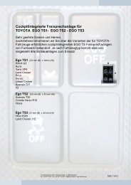
Accessories<br />
Á<br />
 Ã<br />
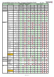
Specific vehicle connection cable<br />
Variant Vehicle Equipment Connecting cable<br />
<strong>Corolla</strong> E12 Standard MY2001>2004 <strong>Toyota</strong><br />
A Land Cruiser J12 Standard<br />
DENGS-00982-07<br />
Hilux KUN 15/25 Option Wide2DIN (TNS310)<br />
FWD 1284-01000<br />
Avensis T25<br />
Standard<br />
Full Map Navigation<br />
Yaris XP9 Standard<br />
<strong>Corolla</strong> Verso R10<br />
Standard MY2004><br />
Full Map Navigation<br />
B<br />
<strong>Corolla</strong> E12<br />
Prius<br />
RAV4 A3<br />
Standard<br />
Full Map Navigation<br />
Standard<br />
Full Map Navigation<br />
<strong>Toyota</strong><br />
DENGS-00983-07<br />
FWD 1284-02000<br />
Hilux KUN 15/25 Standard SOL (MP3)<br />
Auris<br />
HIACE<br />
Standard<br />
Full Map Navigation<br />
Avensis T27 Standard<br />
Verso Standard<br />
<strong>Toyota</strong><br />
C Land Cruiser J12 Full Map Navigation<br />
DENGS-00984-07<br />
FWD 1284-03000<br />
<strong>Toyota</strong><br />
E IQ Standard<br />
DENGS-01410-07<br />
FWD 1284-05000<br />
À<br />
16 | 17
8<br />
EGO TS<br />
Technical specifications<br />
External dimensions: Electronics box (L x B x H) 130 mm x 45 mm x 23 mm<br />
External dimensions: Control unit (L x B x H) TS 1 33,7 mm x 22,9 mm x 26,6 mm<br />
Cable length: Control unit 230 mm<br />
TS 2 42,2 mm x 24,2 mm x 20,8 mm<br />
TS 3 39,3 mm x 20,8 mm x 24,2 mm<br />
Operating voltage 11 V to 15 V<br />
Quiescent current (ignition off) max. 0,1 mA<br />
Fuse: Permanent positive 2 A<br />
Fuse: Ignition 1 A<br />
Temperature range -10 °C bis +55 °C<br />
Supported Bluetooth ® Profiles: Handsfree<br />
9<br />
Certification<br />
0681<br />
Fully compliant with the EU R&TTE Directive 1999/5/EC<br />
Model certification according to EU Directive 72/245/EWG (2006/28/EC) “Electromagnetic compatibility<br />
in motor vehicles”<br />
Bluetooth ® is a registered brand name of Bluetooth SIG, Inc.
10<br />
Hotline<br />
Any questions or suggestions? Would you like some more detailed information? Do you need an<br />
adviser or service in your area? Just give us a call!<br />
Our Hotline Team is there to help you at the following times:<br />
Monday–Thursday from 7.00 a.m. to 5.00 p.m.<br />
Friday from 7.00 a.m. to 4.00 p.m.<br />
Before you call us with your problem, please check first with the following steps:<br />
→ Check whether you can solve your problem with the „Troubleshooting“ checklist in chapter.<br />
→ Try to explain your problem as precisely as possible.<br />
You can contact our Hotline Team at the following numbers:<br />
From Germany: Phone: 0800 - 0 393 393<br />
From outside Germany: Phone: +49 (0) 3377 - 316 233<br />
+49 (0) 3377 - 316 234<br />
Fax: +49 (0) 3377 - 316 244<br />
18 | 19
<strong>Funkwerk</strong> <strong>Dabendorf</strong> <strong>GmbH</strong><br />
Märkische Straße<br />
D-15806 <strong>Dabendorf</strong><br />
Germany<br />
Phone +49 (0) 3377 316 - 0<br />
Fax +49 (0) 3377 316 - 300<br />
Email info@fwd-online.de<br />
service@fwd-online.de<br />
Internet www.fwd-online.de A <strong>Funkwerk</strong> AG company.<br />
<strong>Funkwerk</strong> <strong>Dabendorf</strong> reserves the right to modifications in the course of technological progress and deviations from the delivery<br />
scope! All rights reserved! Reproduction, in whole or in part, is only permitted with the prior written consent of <strong>Funkwerk</strong> <strong>Dabendorf</strong><br />
<strong>GmbH</strong>!<br />
EGO TS