Drive Solutions for the Global Oil and Gas Industry ... - GE Energy
Drive Solutions for the Global Oil and Gas Industry ... - GE Energy
Drive Solutions for the Global Oil and Gas Industry ... - GE Energy

You also want an ePaper? Increase the reach of your titles
YUMPU automatically turns print PDFs into web optimized ePapers that Google loves.
Three-<br />
Phase Electric<br />
Electric Supply<br />
Supply<br />
Calculations <strong>for</strong> Mechanical Speed Control Systems<br />
Calculations <strong>for</strong> Mechanical Speed Control Systems<br />
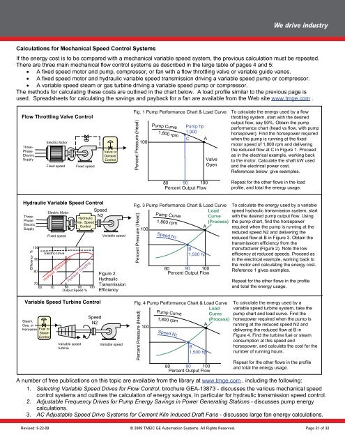
If <strong>the</strong> energy cost is to be compared with a mechanical variable speed system, <strong>the</strong> previous calculation must be repeated.<br />
There If <strong>the</strong> energy are three cost main is to mechanical be compared flow with control mechanical systems as variable described speed in system, <strong>the</strong> large <strong>the</strong> table previous of pages calculation 4 <strong>and</strong> 5: must be repeated.<br />
There<br />
•<br />
are<br />
A fixed<br />
three<br />
speed<br />
main mechanical<br />
motor <strong>and</strong> pump,<br />
flow control<br />
compressor,<br />
systems<br />
or<br />
as<br />
fan<br />
described<br />
with a flow<br />
in <strong>the</strong><br />
throttling<br />
large table<br />
valve<br />
of<br />
or<br />
pages<br />
variable <strong>and</strong><br />
guide<br />
5:<br />
vanes.<br />
• A fixed<br />
fixed<br />
speed<br />
speed<br />
motor<br />
motor<br />
<strong>and</strong><br />
<strong>and</strong><br />
hydraulic<br />
pump, compressor,<br />
variable speed<br />
or fan<br />
transmission<br />
with flow throttling<br />
driving a<br />
valve<br />
variable<br />
or variable<br />
speed pump<br />
guide<br />
or<br />
vanes.<br />
compressor.<br />
• A variable<br />
fixed speed<br />
speed<br />
motor<br />
steam<br />
<strong>and</strong><br />
or<br />
hydraulic<br />
gas turbine<br />
variable<br />
driving<br />
speed<br />
a variable<br />
transmission<br />
speed pump<br />
driving<br />
or compressor.<br />
variable speed pump or compressor.<br />
The methods variable <strong>for</strong> calculating speed steam <strong>the</strong>se or costs gas turbine are outlined driving in <strong>the</strong> variable chart speed below. pump A load or profile compressor. similar to <strong>the</strong> previous page is<br />
used. The methods Spreadsheets <strong>for</strong> calculating <strong>for</strong> calculating <strong>the</strong>se costs <strong>the</strong> savings are outlined <strong>and</strong> payback in <strong>the</strong> chart <strong>for</strong> below. a fan are available load profile from similar <strong>the</strong> Web to <strong>the</strong> site previous www.tmge.com page is .<br />
used. Spreadsheets <strong>for</strong> calculating <strong>the</strong> savings <strong>and</strong> payback <strong>for</strong> fan are available from <strong>the</strong> Web site www.tmge.com Fig. 1 Pump Per<strong>for</strong>mance Chart & Load Curve To calculate <strong>the</strong> energy used by a flow<br />
Flow Throttling Valve Control<br />
Fig. 1 Pump Per<strong>for</strong>mance Chart & Load Curve To throttling calculate system, <strong>the</strong> energy start with used <strong>the</strong> by desired a flow<br />
Flow Throttling Valve Control<br />
throttling output flow, system, say 90%. start Obtain with <strong>the</strong> <strong>the</strong> desired pump<br />
Pump hp<br />
output per<strong>for</strong>mance flow, say chart 90%. (head Obtain vs flow, <strong>the</strong> pump with pump<br />
Pump 1,900 hp<br />
per<strong>for</strong>mance horsepower). chart Find <strong>the</strong> (head horsepower vs flow, with required pump<br />
1,900<br />
C A<br />
horsepower). when <strong>the</strong> pump Find is running <strong>the</strong> horsepower at <strong>the</strong> fixed required<br />
Electric Motor<br />
100<br />
C A<br />
when <strong>the</strong> pump is running at <strong>the</strong> fixed<br />
Electric Motor<br />
100<br />
motor speed of 1,800 rpm <strong>and</strong> delivering<br />
Threemotor<br />
speed of 1,800 rpm <strong>and</strong> delivering<br />
Three- Phase<br />
Valve or<br />
<strong>the</strong> reduced flow at C in Figure 1. Proceed<br />
Phase Electric<br />
Valve Damper or<br />
<strong>the</strong> as in reduced <strong>the</strong> electrical flow at example, C in Figure working 1. Proceed back<br />
Electric Supply<br />
Damper Control<br />
Valve as to <strong>the</strong> in <strong>the</strong> motor. electrical Calculate example, <strong>the</strong> shaft working kW used back<br />
Supply<br />
Control<br />
Valve<br />
Fixed speed Fixed speed<br />
Open to <strong>and</strong> <strong>the</strong> <strong>the</strong> motor. electrical Calculate power <strong>the</strong> cost. shaft kW used<br />
Fixed speed Fixed speed<br />
Open <strong>and</strong> References <strong>the</strong> electrical below power give examples. cost.<br />
References below give examples.<br />
80 90 100<br />
Repeat <strong>for</strong> <strong>the</strong> o<strong>the</strong>r flows in <strong>the</strong> load<br />
80 Percent Output 90 Flow 100<br />
Repeat profile, <strong>and</strong> <strong>for</strong> <strong>the</strong> total o<strong>the</strong>r energy flows in usage. <strong>the</strong> load<br />
Percent Output Flow<br />
profile, <strong>and</strong> total <strong>the</strong> energy usage.<br />
Hydraulic Variable Speed Control<br />
Hydraulic Variable Speed Control<br />
Speed<br />
Electric Motor<br />
Three-<br />
Speed<br />
Electric Motor<br />
N2<br />
Hydraulic<br />
Phase<br />
N2<br />
Efficiency % %<br />
100<br />
100<br />
90<br />
90<br />
80<br />
80<br />
Fixed speed<br />
Fixed speed<br />
Var. Hydraulic Speed<br />
Var. Control Speed<br />
Control<br />
70<br />
70 60 70 *<br />
*<br />
60 70<br />
Output 80 80 Speed 90 90<br />
%<br />
100<br />
100<br />
Output Speed %<br />
Variable Speed Turbine Control<br />
Variable Speed Turbine Control<br />
Steam,<br />
Steam, <strong>Gas</strong>, or<br />
<strong>Gas</strong>, Kerosene or Fuel or<br />
Kerosene Fuel Steamor<br />
Control Steam<br />
Control<br />
Electric <strong>Drive</strong><br />
Electric <strong>Drive</strong><br />
Hydraulic Transmission<br />
Hydraulic Transmission<br />
Hydraulic Coupling<br />
Hydraulic Coupling<br />
Variable speed<br />
Variable turbine speed<br />
turbine<br />
Speed<br />
Speed N2<br />
N2<br />
Variable speed<br />
Variable speed<br />
Figure 2.<br />
Figure Hydraulic 2.<br />
Hydraulic Transmission<br />
Transmission<br />
Efficiency<br />
Efficiency<br />
Variable speed<br />
Variable speed<br />
Percent Pressure (Head)<br />
Pump Curve<br />
Pump Curve<br />
1,800 rpm<br />
1,800 rpm<br />
Fig. 3 Pump Per<strong>for</strong>mance Chart & Load Curve<br />
Fig. 3 Pump Per<strong>for</strong>mance Chart & Load Load Curve<br />
Load Curve<br />
Curve (Process)<br />
A (Process)<br />
100<br />
A<br />
100<br />
Percent Pressure (Head)<br />
Fig. 4 Pump Per<strong>for</strong>mance Chart & Load Curve<br />
Fig. 4 Pump Per<strong>for</strong>mance Chart & Load Load Curve<br />
Load Curve<br />
Curve (Process)<br />
A (Process)<br />
100<br />
A<br />
100<br />
Percent Pressure (Head)<br />
Pump Curve<br />
Pump Curve<br />
1,800 rpm<br />
1,800 rpm<br />
Speed N2<br />
Speed N2<br />
80 90 100<br />
80Percent Output 90 Flow 100<br />
Percent Output Flow<br />
Pump Curve<br />
Pump Curve<br />
1,800 rpm<br />
1,800 rpm<br />
Speed N2<br />
Speed N2<br />
B<br />
B1,500 hp<br />
1,500 hp<br />
B<br />
B1,500 hp<br />
1,500 hp<br />
80 90 100<br />
80Percent Output 90 Flow 100<br />
Percent Output Flow<br />
To calculate <strong>the</strong> energy used by a variable<br />
To speed calculate hydraulic <strong>the</strong> transmission energy used by system, a variable start<br />
speed with <strong>the</strong> hydraulic desired pump transmission output flow. system, Using start<br />
with <strong>the</strong> pump <strong>the</strong> desired chart, find pump <strong>the</strong> output horsepower flow. Using<br />
<strong>the</strong> required pump when chart, <strong>the</strong> find pump <strong>the</strong> horsepower is running at <strong>the</strong><br />
required reduced speed when <strong>the</strong> N2 pump <strong>and</strong> delivering is running <strong>the</strong> at <strong>the</strong><br />
reduced speed flow at N2 B in <strong>and</strong> Figure delivering 3. Obtain <strong>the</strong> <strong>the</strong><br />
reduced transmissiom flow at efficiency B in Figure from 3. <strong>the</strong> Obtain <strong>the</strong><br />
transmissiom manufacturer (Figure efficiency 2). from Note <strong>the</strong> <strong>the</strong> low<br />
manufacturer efficiency at reduced (Figure speeds. 2). Note Proceed <strong>the</strong> low as<br />
efficiency in <strong>the</strong> electrical at reduced example, speeds. working Proceed back as to<br />
in <strong>the</strong> <strong>the</strong> motor electrical <strong>and</strong> calculating example, working <strong>the</strong> energy back cost. to<br />
<strong>the</strong> Reference motor <strong>and</strong> 1 gives calculating examples. <strong>the</strong> energy cost.<br />
Reference 1 gives examples.<br />
Repeat <strong>for</strong> <strong>the</strong> o<strong>the</strong>r flows in <strong>the</strong> profile<br />
Repeat <strong>and</strong> total <strong>for</strong> <strong>the</strong> <strong>the</strong> energy o<strong>the</strong>r usage. flows in <strong>the</strong> profile<br />
<strong>and</strong> total <strong>the</strong> energy usage.<br />
To calculate <strong>the</strong> energy used by a<br />
To variable calculate speed <strong>the</strong> turbine energy system, used by take a <strong>the</strong><br />
variable pump chart speed <strong>and</strong> turbine load curve. system, Find take <strong>the</strong> <strong>the</strong><br />
pump horsepower chart <strong>and</strong> required load when curve. <strong>the</strong> Find pump <strong>the</strong> is<br />
horsepower running at <strong>the</strong> required reduced when speed <strong>the</strong> N2 pump <strong>and</strong>is<br />
running delivering at <strong>the</strong> reduced flow speed at B N2 in<strong>and</strong><br />
delivering Figure 4. Find <strong>the</strong> reduced <strong>the</strong> turbine flow fuel at B or insteam<br />
Figure consumption 4. Find at <strong>the</strong> this turbine speed fuel <strong>and</strong>or steam<br />
consumption horsepower, <strong>and</strong> at this calculate speed <strong>the</strong> <strong>and</strong>cost <strong>for</strong> <strong>the</strong><br />
horsepower, number of running <strong>and</strong> calculate hours. <strong>the</strong> cost <strong>for</strong> <strong>the</strong><br />
number of running hours.<br />
Repeat <strong>for</strong> <strong>the</strong> o<strong>the</strong>r flows in <strong>the</strong> profile<br />
Repeat <strong>and</strong> total <strong>for</strong> <strong>the</strong> <strong>the</strong> energy o<strong>the</strong>r usage. flows in <strong>the</strong> profile<br />
<strong>and</strong> total <strong>the</strong> energy usage.<br />
A number of free publications on this topic are available from <strong>the</strong> library at www.tmge.com , including <strong>the</strong> following:<br />
number of free publications on this topic are available from <strong>the</strong> library at www.tmge.com , including <strong>the</strong> following:<br />
1. Selecting Variable Speed <strong>Drive</strong>s <strong>for</strong> Flow Control, brochure <strong>GE</strong>A-13873 - discusses <strong>the</strong> various mechanical speed<br />
1. control Selecting systems Variable <strong>and</strong> Speed outlines <strong>Drive</strong>s <strong>the</strong> calculation <strong>for</strong> Flow Control, of energy brochure savings, <strong>GE</strong>A-13873 in particular discusses <strong>for</strong> hydraulic <strong>the</strong> various transmission mechanical speed speed control.<br />
2. control Adjustable systems Frequency <strong>and</strong> outlines <strong>Drive</strong>s <strong>the</strong> <strong>for</strong> Pump calculation <strong>Energy</strong> of energy Savings savings, Power in Generating particular <strong>for</strong> Stations hydraulic - discusses transmission pump speed energy control.<br />
2. calculations.<br />
Adjustable Frequency <strong>Drive</strong>s <strong>for</strong> Pump <strong>Energy</strong> Savings in Power Generating Stations discusses pump energy<br />
3. AC calculations. Adjustable Speed <strong>Drive</strong> Systems <strong>for</strong> Cement Kiln Induced Draft Fans - discusses large fan energy calculations.<br />
3. AC Adjustable Speed <strong>Drive</strong> Systems <strong>for</strong> Cement Kiln Induced Draft Fans discusses large fan energy calculations.<br />
Revised: 5-22-09 © 2009 TMEIC <strong>GE</strong> Automation Systems. All Rights Reserved.<br />
Page 31 of 32