Air heating - Giordano Benicchi
Air heating - Giordano Benicchi
Air heating - Giordano Benicchi

You also want an ePaper? Increase the reach of your titles
YUMPU automatically turns print PDFs into web optimized ePapers that Google loves.
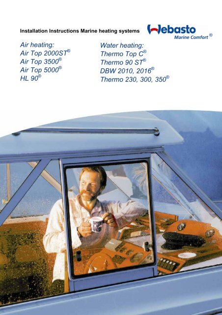
Installation Instructions Marine <strong>heating</strong> systems<br />
<strong>Air</strong> <strong>heating</strong>:<br />
<strong>Air</strong> Top 2000ST ®<br />
<strong>Air</strong> Top 3500 ®<br />
<strong>Air</strong> Top 5000 ®<br />
HL 90 ®<br />
®<br />
Water <strong>heating</strong>:<br />
Thermo Top C ®<br />
Thermo 90 ST ®<br />
DBW 2010, 2016 ®<br />
Thermo 230, 300, 350 ®
Marine <strong>heating</strong> system Installation Instructions<br />
Table of contents<br />
1 Safety instructions ........................................................................................3<br />
2 General ...........................................................................................................4<br />
3 Heating system selection .............................................................................5<br />
4 Installation of the <strong>heating</strong> system................................................................6<br />
5 Exhaust...........................................................................................................9<br />
6 Combustion air supply................................................................................12<br />
7 Fuel supply...................................................................................................13<br />
8 Electrics........................................................................................................18<br />
9 <strong>Air</strong> heaters....................................................................................................19<br />
10 Water heaters...............................................................................................30<br />
11 Acceptance and Commissioning ...............................................................38<br />
12 Operating instructions ................................................................................38<br />
13 Maintenance and Service............................................................................39<br />
Symbols used<br />
Specific risk of injury or fatal accidents<br />
Legal regulations and technical documentation<br />
Specific risk of fire or explosion<br />
Reference to a special technical feature<br />
Recommendations<br />
This brochure supplements the device-specific installation and operating<br />
instructions for the respective ® <strong>heating</strong> units with information that is required<br />
for installation in marine vessels. It contains important safety instructions and<br />
refers to chapters in the device-specific installation and operating instructions,<br />
which must also be observed.<br />
Read these instructions completely before operating the first time!<br />
If you have still have any questions after reading this brochure: Contact an authorized Webasto ®<br />
Partner (www.webasto-marine.com) or the Webasto ® Support Hotline.<br />
2 © Webasto Global Comfort Solutions ®
Marine <strong>heating</strong> system Installation Instructions<br />
1 Safety instructions<br />
Heating systems should only be installed by an authorized Webasto ® Partner.<br />
If you want to install a Webasto ® heater system yourself:<br />
The installation assumes that you have sufficient technical and craft knowledge and skill.<br />
Unskilled installation can endanger life!<br />
Before first use, the <strong>heating</strong> system must be checked by an authorized<br />
Webasto ® Partner!<br />
DANGER<br />
This is both for your safety and for the safety of third persons.<br />
• With do-it-yourself installation: The installation is extensive and can take, depending on the<br />
boat type and size, between 8 and 40 hours. It presupposes sufficient technical and<br />
craftwork knowledge and skills, for example in boat construction, marine electrical systems,<br />
<strong>heating</strong> engineering and fuel systems.<br />
• Incorrect installation or repair of Webasto ® <strong>heating</strong> systems may cause a fire or<br />
result in the emission of carbon monoxide, which can be fatal. Serious or fatal<br />
injuries can be caused as a result.<br />
• Observe carefully: applicable accident prevention regulations and workshop and<br />
work safety instructions.<br />
• Observe regional regulations! Clarify which regulations apply for the planned use<br />
of the boat. Check these! If necessary, obtain official permission.<br />
• ALWAYS obey: Installation and repair instructions. If there are any doubts, safety questions<br />
or technical questions: obtain professional support from an authorized Webasto ® Partner<br />
(www.webasto-marine.com) or the Webasto ® Support Hotline!<br />
• Failure to observe individual points can lead to damage to the <strong>heating</strong> system or the boat.<br />
• Pay attention to all warnings!<br />
• Follow the technical rules!<br />
• Only use original accessories and original spare parts.<br />
• Only use approved Webasto ® control components! Otherwise there is a risk of malfunctions.<br />
• For accessories, installation and assembly components, see the Webasto ® parts catalog<br />
• The example installations shown in this documentation are for information purposes only. No<br />
liability can be derived from the installation examples shown.<br />
© Webasto Global Comfort Solutions ® 3
Marine <strong>heating</strong> system Installation Instructions<br />
• WARNING! When positioning the exhaust outlet, prevent the re-entry of the<br />
exhaust gasses into the warm air system or the accommodation areas. Danger of<br />
suffocation!<br />
• WARNING! Never feed combustion air into the accommodation areas. Danger of<br />
suffocation!<br />
• WARNING! The <strong>heating</strong> system must be turned off while refueling.<br />
• WARNING! Use only fire resistant fuel lines and temperature proof thermally<br />
insulated <strong>heating</strong> air hoses. Fire risk!<br />
• WARNING! Do not blow hot air directly onto living creatures or temperature<br />
sensitive parts.<br />
2 General<br />
Use of the <strong>heating</strong> system<br />
Solely for use on ships:<br />
• For the pre-<strong>heating</strong> and <strong>heating</strong> of ship cabins, cargo holds, personnel and crew<br />
transportation areas<br />
• on inland waters and at sea<br />
• for sailing and motor boats from approximately 8 to 28 m in length<br />
Not suitable for<br />
• continuous <strong>heating</strong> of living areas, houseboats, etc.<br />
• for <strong>heating</strong> and/or drying living beings<br />
Permits<br />
Existing <strong>heating</strong> system permits with a symbol on type plate:<br />
• EU type permit in accordance with directive 72/245/EWG for electromagnetic compatibility<br />
• EU type permit in accordance with directive 2001/56/EG for fuel-powered <strong>heating</strong><br />
• CE symbol (prescribed in EU for new recreational craft from 2.5 to 24 m length )<br />
Relevant standard for installation<br />
- Recreational craft directive 94/25/EG<br />
- ISO 8845/46 – Protection against ignition of surrounding flammable gasses<br />
- ISO 7840 – Fire-resistant fuel hoses<br />
4 © Webasto Global Comfort Solutions ®
Marine <strong>heating</strong> system Installation Instructions<br />
3 Heating system selection<br />
Criteria for <strong>heating</strong> system selection<br />
• Boat length<br />
• region where used,<br />
• Season and<br />
• Boat form<br />
Simplified graphical representation<br />
1. Select the boat length.<br />
2. Go horizontally to the left to the line for the region.<br />
3. Go vertically downwards to the line for the season when used.<br />
4. Go horizontally to the right.<br />
a) Water heater: Follow the boat type line vertically downwards in the lower triangle.<br />
b) <strong>Air</strong> heater: Follow the boat type line vertically up in the upper right triangle.<br />
More accurate capacity rating of the heat requirement:<br />
calculate approx. 150 to 200 W <strong>heating</strong> capacity per m³ of heated area.<br />
For extreme cold, calculate 250-400 W per m³.<br />
Use the upper or lower guide value according to<br />
• Operating area,<br />
• Boat hull/superstructure insulation,<br />
• Integration of a hot water boiler.<br />
Recommendations:<br />
<strong>Air</strong> <strong>heating</strong> for ships from 15 m: use two systems (better warm air distribution and<br />
controllability, less noise and power consumption). Use separate connections for electricity,<br />
exhaust gas, fuel supply, etc.<br />
© Webasto Global Comfort Solutions ® 5
Marine <strong>heating</strong> system Installation Instructions<br />
4 Installation of the <strong>heating</strong> system<br />
4.1 Choosing the location<br />
• Install the <strong>heating</strong> system in a dry location; protected from the ingress of sea water, excessive<br />
vibration, heat and engine exhaust gasses<br />
• Suit the installation for the type of use/type of boat. Observe: all peripheral components such as<br />
maximum permitted exhaust length, on-board wall duct positions, combustion air intake,<br />
electrical wiring and cable lengths, distance from fuel tank, routing of warm air hoses, fresh air<br />
intake, etc. For data, see the equipment-specific installation instructions.<br />
• Observe: Maximum ship inclination cannot lead to the ingress of sea water through the<br />
exhaust outlet.<br />
• Inclination must not bring the <strong>heating</strong> system into contact with bilge water.<br />
• Do not obstruct moving parts (e.g. rudder assembly)<br />
• When arranging the <strong>heating</strong> system, avoid the danger of injury to persons or the risk of damage<br />
to objects as much as possible.<br />
Fire risk! The <strong>heating</strong> system can overheat.<br />
• Pay attention to maintaining a sufficient distance and sufficient ventilation for all parts.<br />
• Use only fire resistant materials.<br />
• If necessary, fit a heat shield.<br />
• Do not install in the vicinity of flammable or temperature-sensitive objects such as sails,<br />
fenders, bulkheads, paper, gas lines, fuel containers, etc.<br />
• When installing in a lockers or control cabinets;<br />
• Only with good ventilation<br />
• Prevent contact with hot parts<br />
• If necessary, create a contact barrier around the <strong>heating</strong> system<br />
DANGER<br />
• Recommended locations:<br />
o not next to sleeping berths or next to the salon (because of ventilation noise)<br />
o in lockers or control cabinets, if the are well ventilated.<br />
If necessary create a contact barrier around the <strong>heating</strong> system so that the sail, fender,<br />
bulkheads, etc. do not come into contact with hot parts.<br />
o in the engine compartment of inboard diesel engines. Assuming: Hot air intake from outside,<br />
combustion air intake from outside or the engine compartment if this is well ventilated to the<br />
outside.<br />
6 © Webasto Global Comfort Solutions ®
Marine <strong>heating</strong> system Installation Instructions<br />
Heating system installation in lockers (1), control cabinets (2) or engine compartment (3).<br />
4.2 Equipment orientation<br />
Permissible installation locations: see device-specific installation instructions.<br />
0-90˚ 0-90˚ 0-90˚<br />
Examples of permissible installation locations for <strong>Air</strong> Top ® air <strong>heating</strong> system and Thermo 90 ST ® water<br />
<strong>heating</strong> system<br />
• Installation locations: consider possible ship inclination.<br />
• Recommended installation location: exhaust outlet downwards, heater parallel to ship’s<br />
longitudinal axis.<br />
• Do not install transversely in sailing boats.<br />
Exception: if heater operation is only when moored or in motorboats then installation<br />
transverse to the longitudinal axis is also permissible.<br />
Install heater system along the longitudinal axis in sailing boats.<br />
© Webasto Global Comfort Solutions ® 7
Marine <strong>heating</strong> system Installation Instructions<br />
4.3 Heater mounting<br />
• Securely mount the equipment (vibration, swell)!<br />
• Use a mounting assembly or bracket<br />
<strong>Air</strong> heaters: use the bracket and rubber seals provided under the feet of the equipment.<br />
Securing <strong>Air</strong> Top ® using the mounting bracket<br />
• Recommendation: flexible mountings (decoupling oscillations, noise reduction)<br />
• Secure the heater unit with screws to the mounting assembly.<br />
• Recommendation, if attached to the outside skin of GRP boats: Laminate a wooden plate on<br />
the inside at the mounting location to avoid having to drill through the outer skin.<br />
WARNING! When drilling into the outer skin of the ship there is a risk of drowning!<br />
Drilling under the water line can cause the ship to sink.<br />
If the boat is in the water: check the drilling location. Keep leak sealing equipment<br />
available and familiarize yourself with the possible escape routes.<br />
8 © Webasto Global Comfort Solutions ®
Marine <strong>heating</strong> system Installation Instructions<br />
5 Exhaust<br />
5.1 Exhaust system<br />
Feed the combustion gasses out of the boat through the exhaust system.<br />
1) Heater; 2) Combustion air intake; 3) Flexible stainless steel exhaust pipe; 4) Condensation drain;<br />
5) Exhaust gas sound absorber; 6) Isolation; 7) Goose neck; 8) On-board duct<br />
5.2 Exhaust outlet<br />
Outlet arrangement:<br />
• Position the exhaust outlet where as little water spray can enter as possible.<br />
Recommendation:<br />
Sail boat: in the stern transom.<br />
Motor boat: in the lateral side wall.<br />
WARNING! Do not position the exhaust outlet underneath or next to ventilation<br />
equipment, window openings or the <strong>heating</strong> air intake (risk of suffocation).<br />
• at least 60 cm above the water line so that no water can enter when the boat heels.<br />
• do not connect to the engine or generator exhaust line (higher pressure, damage to the<br />
heater).<br />
• not in the direction of movement of the boat (higher wind pressure).<br />
• not where it can be covered easily, e.g. by the fender.<br />
Wall ducts:<br />
• Choose the design and installation position: minimize rain water ingress.<br />
• Only metals ducts are permissible. Use insulating washers for thermal isolation from the walls.<br />
Use properly fitting seals (minimizing water ingress).<br />
If additional seals are needed: use heat-resistant sealant only.<br />
• Wall ducts: Not sealable; not with self-opening valves.<br />
© Webasto Global Comfort Solutions ® 9
Marine <strong>heating</strong> system Installation Instructions<br />
Always assemble wall ducts with seals.<br />
5.3 Exhaust pipe<br />
5.3.1 Exhaust pipe<br />
Use 2-layer stainless steel flexible exhaust pipe.<br />
• Keep the exhaust pipe as short as possible (maximum exhaust pipe length: see device-specific<br />
installation instructions).<br />
• Route the exhaust pipe as straight as possible (permissible number of bends, smallest<br />
permissible curve radius: see device-specific installation instructions).<br />
• No contact with temperature-sensitive objects such as electrical cables, water pipes, plastic<br />
parts, sails or boat hull.<br />
• Minimum wall distance: ≥ 20 mm.<br />
• Minimum pipe diameters; see device-specific installation instructions.<br />
5.3.2 Exhaust gas pipes in personnel accommodation<br />
WARNING! Avoid installing the heater and exhaust pipes in personnel accommodation<br />
if possible. (Danger of suffocation if routing is inappropriate)<br />
• If unavoidable: use rigid stainless steel pipes with a wall thickness ≥ 1mm.<br />
• Replace pipes with new ones after ≤ 10 years.<br />
• Make the joints especially precise and gas tight.<br />
• Use high temperature resistant sealing compound.<br />
5.4 Exhaust pipe connections<br />
• When routing the exhaust pipes, pay attention: all connections must be sealed.<br />
• Use only Webasto ® approved hose connections. No hose clamps.<br />
•<br />
Permitted hose clamps for exhaust pipe mounting<br />
10 © Webasto Global Comfort Solutions ®
Marine <strong>heating</strong> system Installation Instructions<br />
5.5 Thermal isolation<br />
When routing the exhaust pipe, pay attention to:<br />
• Avoid contact between the hot exhaust pipes with temperature-sensitive objects such as<br />
electrical cables, water pipes, plastic parts, sails or boat hull.<br />
• If contact with persons/objects during operation is possible: Insulate the exhaust pipes or fit<br />
shielding. Use suitable exhaust pipe insulation: see the Webasto ® parts catalog.<br />
• Surface temperature ≤ 80°C!<br />
• Minimum distance from walls 20 mm<br />
5.6 Goose neck<br />
Last section of the exhaust pipe: goose neck pointing downwards to outlet<br />
(against possible ingress of water) Height of goose neck: ≥ 20 cm.<br />
5.7 Condensation drain<br />
With an exhaust pipe > 2 m, fit a condensation drain (not rusting)<br />
A) With a t-piece at the lowest point in the exhaust pipe or<br />
B) if the heater itself is at the lowest point: exhaust pipes with integrated condensation drain.<br />
Use suitable components: see the Webasto ® parts catalog.<br />
If necessary, use a drain trap or drain hose for the condensation.<br />
There are various models of condensation drain pipes<br />
5.8 Silencer<br />
Recommendation: use an exhaust silencer. It gives a significant noise reduction.<br />
No condensation drain holes in the silencer (escaping exhaust).<br />
Suitable models: see the Webasto ® parts catalog.<br />
© Webasto Global Comfort Solutions ® 11
Marine <strong>heating</strong> system Installation Instructions<br />
6 Combustion air supply<br />
6.1 Combustion air circulation<br />
Observe carefully:<br />
• Intake from are well ventilated from the outside at ambient pressure and/or directly from the<br />
outside.<br />
Do not extract intake air from accommodation/cabins. Danger of suffocation!<br />
• Intake location: no intake of exhaust gasses (from heater and/or engine).<br />
6.1.1 Intake of combustion air from area well ventilated from the outside<br />
(locker, storage area or engine compartment)<br />
• No on-board ducts needed.<br />
• Intake area must be at ambient pressure and be sufficiently ventilated to the outside.<br />
• When intake is in the engine compartment: the engine compartment ventilation blower may<br />
not create an under-pressure or overpressure in the engine compartment.<br />
6.1.2 Combustion air intake directly from outside<br />
• Use separate on-board ducts when an intake from a ventilated area is not possible.<br />
• Route the end of the intake hose like a goose neck, as shown in the illustration.<br />
• Do not arrange on-board ducts in the direction of travel (other pressure build-up and water<br />
ingress in the intake pipe is possible).<br />
• Make a drain hole at the lowest point, as shown in the illustration.<br />
• Route the hose so that it is kink free.<br />
Combustion air intake from outside through an on-board duct<br />
12 © Webasto Global Comfort Solutions ®
Marine <strong>heating</strong> system Installation Instructions<br />
6.2 Intake hose<br />
• Use is optional, not mandatory.<br />
• Drill a Ø 5 mm condensation opening in the downward line from the heater and/or use a<br />
separate condensation drain, see illustration.<br />
• Fit a cap over the end of the hose as a protection against ingress.<br />
• <strong>Air</strong> intake arrangement: cannot be blocked by objects.<br />
• Intake hose as short as possible. Permissible intake length: see device-specific installation<br />
instructions.<br />
• Secure the intake hose: with hose clamps to at the heater intake hoses and with pipe clamps<br />
or cable ties to fixed fittings.<br />
• Recommendation: Use intake silencers (intake noise). Supplied with <strong>Air</strong> Top <strong>heating</strong><br />
systems. Otherwise: for suitable silencers see the parts catalog.<br />
• Pay attention, if the metering pump cable is fed through the intake pipes: avoid pinching the<br />
intake hose during assembly. Do not use metal intake hoses.<br />
• Route the hose so that it is kink free.<br />
7 Fuel supply<br />
• During installation comply with national or local directives. If necessary, ask your local<br />
authorized Webasto ® Partner.<br />
• Protect the boat hull/construction in the vicinity of the heater from the effects of<br />
heat/contamination by fuel/oil.<br />
Example <strong>Air</strong> Top ® heater fuel supply<br />
1) Metering pump; 2) Fuel inlet; 3) Tank inlet; 4) Tank; 5) Fuel line; 6) Heater<br />
7.1 Pipe lengths and lifting height<br />
Observe the maximum permissible fuel intake height and/or lifting height for the dosing pump during<br />
installation. Lengths: see device-specific installation instructions.<br />
Example of the lifting heights for <strong>Air</strong> Top ® , Thermo Top C ® , Thermo 90ST ® <strong>heating</strong> systems:<br />
• Metering pump: Installation max. 500 mm below the tank surface level.<br />
• Total intake length (A+B) < 2 m.<br />
• C+D at pump pressure side < 6 m.<br />
• Total lifting height D < 3 m.<br />
© Webasto Global Comfort Solutions ® 13
Marine <strong>heating</strong> system Installation Instructions<br />
Permissible pipe lengths and lifting heights<br />
7.2 Fuel take-off<br />
For taking off the fuel for the heater there are the following alternatives:<br />
7.2.1 Tank take-off device<br />
• Fuel take-off directly from the boat’s fuel tank.<br />
• Plastic tanks: install tank take-off in tank fitting. Do not drill into a plastic tank.<br />
• Suitable tank take-off for metal tanks: see parts catalog and/or scope of delivery.<br />
Installation of a tank take-off in metal tanks<br />
Fit a tank take-off as shown in illustration:<br />
1. Shorten the immersion tube: the end should be approx. 25 mm from the bottom of the tank.<br />
Cut the hose diagonally. Deburr the cut end.<br />
2. Cut a hole in the top of the tank or tank fitting. Use a suitable drilling attachment. Grease the<br />
drill and drilling surface in advance (to catch small drill swarf).<br />
3. Insert the take-off into the hole and screw tight (seal lightly compressed).<br />
7.2.2 Tank drain pipes<br />
If an unused tank drain pipe is already fitted to the boat’s tank, use this.<br />
Do not use a tank discharge screw at the bottom since contamination or water can be taken up.<br />
14 © Webasto Global Comfort Solutions ®
Marine <strong>heating</strong> system Installation Instructions<br />
7.2.3 Fuel extractor<br />
Fuel extractor with in-built blister separator<br />
The fuel extractor is a special t-piece with an integrated blister separator. Installation is possible in<br />
the feed to the engine if no priming pump is available in the tank, or in the engine return feed if this<br />
reaches nearly to the bottom of the tank. When selecting the fuel extractor, pay attention to the<br />
available pipe diameter.<br />
7.3 Fuel line<br />
Fuel line material (metal/plastic): comply with regional/national regulations!<br />
Fire risk! In the engine compartment, fuel lines must be metal and<br />
connecting hoses between separate components must be made of<br />
fire resistant material (DIN-EN-ISO 7840).<br />
Installation kits for metal fuel lines: see parts catalog.<br />
Use stainless steel hose clamps for fuel lines.<br />
• Use only stainless steel hose clamps to secure plastic fuel lines.<br />
• Metal pipes: pay attention to clean working. Before assembly, remove all contamination and<br />
burrs from the junction points.<br />
• Do not over-tighten union nuts (otherwise leaks will occur).<br />
• Route the fuel line as straight as possible and slightly ascending so that air bubble escape<br />
towards the heater.<br />
• Secure the line at regular distances, avoid kinks.<br />
• Keep away from heat sources.<br />
7.4 Metering pump<br />
The metering pump of some <strong>heating</strong> systems is supplied through its own cable harness and<br />
depending on the heat capacity required feeds the fuel into the combustion chamber of the heater.<br />
Because of their individual propeller blades, the separate metering pumps make a ticking noise.<br />
© Webasto Global Comfort Solutions ® 15
Marine <strong>heating</strong> system Installation Instructions<br />
• Fit the metering pump close to the tank. Distance from the tank take-off is ≤ 1.2 m.<br />
• Install the pump in a dry/cool area. Do not install in the bilge.<br />
• Pay attention to the pump flow direction.<br />
• Use flexible mountings for the metering pump (reduces the transmission of impeller<br />
noise/ticking).<br />
• Recommended installation: suspended from solid boat structures.<br />
• Recommended fuel line mounting: Distance from metering pump ≥ 20cm or in an elbow<br />
so that no impeller noise is conducted through the pipes.<br />
Fuel line mounting at wall (top view) should not be too close to the metering pump<br />
• Attach the metering pump horizontally.<br />
Assembly orientation of the metering pump<br />
If the metering pump has a plastic fuel damper, if it is installed in the engine compartment it must<br />
be protected with a protective sleeve (see parts catalog).<br />
16 © Webasto Global Comfort Solutions ®
7.5 Fuel filter<br />
Marine <strong>heating</strong> system Installation Instructions<br />
Use of a fuel filter is necessary for protecting from contamination. Install before the metering<br />
pump.<br />
If installing in the engine compartment, use only fire-resistant types in accordance with ISO 7840.<br />
7.6 Auxiliary tank<br />
If an auxiliary tank is required for the <strong>heating</strong> system fuel supply:<br />
installation only by a specialist in marina applications (know-how about applicable standards,<br />
regulations and directives).<br />
7.7 Special instruction for petrol-driven heaters in boats<br />
WARNING!<br />
The inappropriate installation of a petrol-driven heater in a petrol-driven boat increases<br />
the fire hazard. Local regulations as well as special safety measures are to be<br />
observed.<br />
Installation of a petrol-driven heater is only to be carried out by an authorized Webasto ® Partner<br />
and/or with the direct support of Webasto ® !<br />
• The motor compartment of petrol-driven boats and ships must be vented before the <strong>heating</strong><br />
system is started. Appropriate stickers must be affixed close to the controls.<br />
• Do not install <strong>heating</strong> systems where flammable vapors can accumulate.<br />
• The combustion air intake must come from the outside, not from the engine compartment.<br />
• Components with a surface temperature > 80°C are not permitted – use insulation.<br />
• Install the metering pump in the coolest place possible
Marine <strong>heating</strong> system Installation Instructions<br />
8 Electrics<br />
• Heating system power supply: from the boat’s service battery (not the starter batteries for the<br />
driving engine because of the risk of discharge).<br />
• Electrical connection: see device-specific installation instructions.<br />
• Note: all data and safety instructions.<br />
• Fit an operating indication that is clearly visible for the operator that shows whether<br />
the <strong>heating</strong> is switched on or off.<br />
Note:<br />
• Route all cables and electrical components in dry and protected areas.<br />
• If there are battery isolation switches in the boat: connect the plus lead from the <strong>heating</strong> system<br />
directly to the positive pole of the service battery. This makes it possible for the <strong>heating</strong> system<br />
to always be switched off afterwards.<br />
• Power supply cables: keep them as short as possible. If necessary, shorten cables.<br />
• Connecting cable diameter: ≥ 4.0 mm². If supply cable > 7.5 m” ≥ 6.0 mm²<br />
• When extending cables, make sure to use an adequate diameter and insulation type.<br />
• Distance of main fuse from battery positive terminal: ≤ 1 m.<br />
• If highly sensitive electronic devices are on board: note any special electrical screening needed.<br />
Contact your authorized Webasto ® Partner.<br />
• Do not touch exposed equipment printed circuit boards (electrostatic discharges).<br />
18 © Webasto Global Comfort Solutions ®
Marine <strong>heating</strong> system Installation Instructions<br />
9 <strong>Air</strong> heaters<br />
9.1 General<br />
Use Heating and ventilation of<br />
- Ships cabins<br />
- Bridges<br />
Installation accessories: see parts catalog.<br />
9.2 Method of operation<br />
<strong>Air</strong> <strong>heating</strong> in lockers draws in outside air over in-built fans and hot air intakes. The air heated in the<br />
heater flows through warm air hoses towards the bow. The warm air enters the cabins through<br />
outlets. Fuel is supplied by separate metering pumps from the boat’s fuel tank. Power is supplied<br />
(for the fan, electronics, etc.) from the boat’s battery. The combustion circuit is separated from the<br />
<strong>heating</strong> circuit. Independent combustion air intake. Exhaust removal through exhaust pipes<br />
including silencers to the outside.<br />
Interior temperature regulation: by cabin temperature sensor and preset value control. The heater<br />
system constantly compares the actual temperature with the selected temperature and<br />
automatically adjusts the <strong>heating</strong> capacity accordingly.<br />
Example of a sailing yacht: 1) <strong>Air</strong> <strong>heating</strong>; 2) Heating air intake; 3) Warm air hose; 4) Outlet;<br />
5) Metering pump; 6) Fuel tank; 7) Exhaust pipe; 8) Temperature sensor; 9) Control<br />
© Webasto Global Comfort Solutions ® 19
Marine <strong>heating</strong> system Installation Instructions<br />
9.3 Hot air intake<br />
WARNING! Hot air intake from a clean area without exhaust gasses. Not from the engine<br />
compartment.<br />
• The intake opening can not be blocked by stowed articles.<br />
• Intake through an inlet hose leads to pressure losses. Consider this in the resistance<br />
calculations.<br />
• Use grilles or intake protection so that foreign objects cannot be drawn into the heater.<br />
It is possible to use the warm air intake for fresh-air operation or recirculation.<br />
9.3.1 Fresh air operation<br />
Draw in <strong>heating</strong> air from the outside, heat and blow into interior areas. This renews the cabin air and<br />
reduces the humidity. Pay attention to the outlet opening in the cabins. For temperature control, an<br />
external temperature sensor should preferably be installed in the salon.<br />
In summer, ventilation is also possible (ventilation switches on the control panel are required).<br />
• Warm air intake directly from the lockers or control cabinets, if this is dry, clean, noise free<br />
and exhaust gas free. For proper ventilation observe an intake diameter of ≥ 1.5 x diameter<br />
of the heater system.<br />
• otherwise use an intake hose for intake from outside.<br />
• Avoid the ingress of water into the intake openings.<br />
<strong>Air</strong> intake for well ventilated lockers<br />
<strong>Air</strong> intake through an inlet hose, straight<br />
from the outside.<br />
9.3.2 Circulation air<br />
With recirculation the <strong>heating</strong> air is taken from the interior air. The advantage is fast arming up<br />
through better use of the heat. However, there is no reduction in the humidity or renewal of the air.<br />
20 © Webasto Global Comfort Solutions ®
Marine <strong>heating</strong> system Installation Instructions<br />
9.4 Hot air circulation<br />
9.4.1 Routing the hoses<br />
WARNING! Fire risk! Only use temperature-resistant Webasto ® hot air hoses.<br />
WARNING! Do not drill into the outer skin of the ship. Risk of drowning.<br />
Risk of injury or damage. Route hot air hoses away from contact and insulate them.<br />
• Hot air circulation: avoid compressing or pinching the hot air hoses.<br />
Recommended hose routing around corners<br />
• Do not route hot air hoses through the bilge.<br />
• Hot air hoses in humid areas: use temperature-resistant, flexible plastic hoses with metal<br />
spirals.<br />
• In storage areas: Protect the hot air hoses from damage by the load, e.g. cover with a perforated<br />
metal cover.<br />
• Recommendation: Routing through bulkheads: use wall ducts as shown in illustration (protect<br />
from chafing). see the Webasto ® parts catalog.<br />
Recommended hose duct through a bulkhead using wall ducts.<br />
© Webasto Global Comfort Solutions ® 21
Marine <strong>heating</strong> system Installation Instructions<br />
• Secure the hoses: with hose clamps on all joints.<br />
• Recommendation for hose routing through areas not to be heated: fit hoses with hose<br />
insulation to prevent heat loss (Webasto Thermoduct ® available as accessory).<br />
9.4.2 Silencers in air circulation<br />
Recommendation: For <strong>Air</strong> Top 5000 ® systems with short hot air supply hoses, use a silencer in<br />
the intake and/or outlet side (noise level reduction). See the parts catalog.<br />
Hot air silencer for reducing the noise levels.<br />
9.4.3 <strong>Air</strong> distribution and outlet<br />
Through an appropriate air distribution, all the required areas in the boat can be evenly heated. To<br />
this end, multiple side branches branch off the main line so as to reach all the cabins. Through an<br />
appropriate selection of branches and diameters you can influence the air flow, and thus the heat<br />
flow.<br />
See the parts catalog for branches, connecting pieces, y-junctions, outlets, etc. made of<br />
temperature-resistant material.<br />
WARNING! Risk of injury. Do not direct hot air onto living beings or temperaturesensitive<br />
objects.<br />
• Hoses: keep them as short as possible (heat loss).<br />
• Hose routing: straight if possible (large curve radii).<br />
• Recommendation: use distributors with control shutters and Bowden cable controls<br />
(regulation of the air flow as required).<br />
• Maintain the hose diameter of the main hose continuously from the heater to the main outlet.<br />
• The outlet from the main hose must not be shuttered in order to prevent over<strong>heating</strong> of the<br />
<strong>heating</strong> system. Side branches: shuttered outlets are possible.<br />
• Note: arrange the outlets so that they do not get blocked.<br />
22 © Webasto Global Comfort Solutions ®
Marine <strong>heating</strong> system Installation Instructions<br />
• Free flow into the cabins enables the best cabin <strong>heating</strong> and air circulation.<br />
• Only use one or two outlets per cabin.<br />
• Position of the outlet: close to the floor (best air circulation).<br />
• Choose an outlet color that matches the interior, see the parts catalog.<br />
When using air distributors, the principle applies that air always takes the route of least<br />
resistance. The type and orientation of the distributor has exactly the same effect as the diameter<br />
and flow resistance of the connected air line.<br />
Rough orientation for distributor selection:<br />
Principles of air distribution with branches<br />
9.4.4 Interpretation using resistance points<br />
Optima heat output of an air <strong>heating</strong> system. <strong>Air</strong> flows if possible unrestrictedly into the interior.<br />
<strong>Air</strong> distribution at the intake and outlet sides present a flow resistance so: keep this resistance<br />
as small as possible.<br />
As a reference point for a maximum permissible air flow, air supply components are given so-called<br />
“resistance points” that represent a value of flow resistance. The greater the number of resistance<br />
points an air supply component has, the worse the air flows through it.<br />
The table of resistance points lists common components and their resistance points.<br />
For the complete parts spectrum, see the Webasto ® parts catalog.<br />
For in-built air supply systems, ensure that the total sum of the resistance points in the main<br />
branch are not exceeded (otherwise there is a risk of the heater over<strong>heating</strong> or premature<br />
reduction of the <strong>heating</strong> capacity while the interior has not yet been warmed up.<br />
<strong>Air</strong> Top 2000 / S / ST ®<br />
<strong>Air</strong> Top 3500 / ST ®<br />
<strong>Air</strong> Top 5000 / ST ®<br />
max. 325 points.<br />
max. 550 points.<br />
max. 375 points.<br />
© Webasto Global Comfort Solutions ® 23
Marine <strong>heating</strong> system Installation Instructions<br />
Determine the resistance points of the planned air lines: total the separate resistance points in the<br />
main line and add the components used.<br />
Main line begins at intake point E and ends at open outlet A.<br />
Example: <strong>Air</strong> Top 5000 ® <strong>Air</strong> line<br />
No. Components<br />
Resistance points<br />
1 Intake grille, Ø 90 mm 65<br />
2 1 m hot air hose, Ø 90 mm curved 25 + 6<br />
3 0.5 m hot air hose, Ø 90 mm straight 0.5 x 25<br />
4 0.4 m hot air hose, Ø 90 mm straight 0.4 x 25<br />
5 Branch, 90/60/90 16<br />
6 1 m hot air hose, Ø 90 mm straight 25<br />
7 0.5 m hot air hose, Ø 90 mm curved 0.5 x 25 + 6<br />
8 Branch, 90/60/90 16<br />
9 0.4 m hot air hose, Ø 90 mm curved 0.4 x 25 + 6<br />
10 1 m hot air hose, Ø 90 mm straight 25<br />
11 Outlet, Ø 90 mm with 90° shutters 33 _<br />
Total<br />
268 points<br />
Total of 268 points is less than the upper limit of 375 points for <strong>Air</strong> Top 5000 ® : Interpretation is good<br />
for flows.<br />
Optimal air distribution:<br />
• short hoses<br />
• few curves<br />
• no reduction of the total diameter<br />
• non-shuttered outlet in main line.<br />
• optimal flow branches and distributors.<br />
24 © Webasto Global Comfort Solutions ®
Marine <strong>heating</strong> system Installation Instructions<br />
Resistance points <strong>Air</strong> Top ® <strong>Air</strong> <strong>heating</strong> system<br />
AT 2000/S/ST ® : 325 P AT 3500/ST ® : 550 P AT5000/ST ® : 375 P<br />
55/60 mm inlet 80 mm inlet 90 mm inlet<br />
Dim.<br />
in mm<br />
Poin<br />
ts<br />
Id.<br />
Dim.<br />
in mm<br />
Poin<br />
ts<br />
Id.<br />
Dim.<br />
in mm<br />
Points<br />
Intake grille 60 24 67492A '--- 90 65 89141A<br />
Flexible<br />
pipe<br />
per meter<br />
Bends in<br />
flexible<br />
hose<br />
55<br />
60<br />
55:<br />
60:<br />
30<br />
27<br />
10<br />
8<br />
411376<br />
398497<br />
411376<br />
398497<br />
80 27 398519 90 25 90395A<br />
80 7 398519 90 6 90395A<br />
Reduction 60->55 27 29852A 90-->60<br />
90-->80<br />
90° device<br />
connection<br />
60 90 29849A<br />
Double<br />
union<br />
55<br />
60<br />
12<br />
10<br />
495638<br />
9009258C<br />
211<br />
45<br />
Id.<br />
9011011C<br />
9009270B<br />
80 5 495646 90 5 9009259C<br />
90° bend 80 50 128503 90 77 9009260C<br />
Branch 55/55/55<br />
60/60/60<br />
11<br />
9<br />
495697<br />
9009264B<br />
80/55/80<br />
80/60/80<br />
80/80/80<br />
12<br />
15<br />
8<br />
495719,<br />
252778<br />
495700,<br />
252786<br />
Branch 60/60/60 21 9009264B 80/80/80 50 495700,<br />
252786<br />
Y-piece 80/55/55<br />
80/60/60<br />
230<br />
201<br />
495689<br />
9009262B<br />
90/60/90<br />
90/60/90<br />
90/80/80<br />
90/90/90<br />
8<br />
16<br />
50<br />
42<br />
9009263B<br />
90999A<br />
91000A<br />
9009261C<br />
T-piece 60/60/60 13 9009266C 90/90/90 13 9009265C<br />
T-piece 60/60/60 63 9009266C 90/90/90 61 9009265C<br />
Distributor 55/55/55<br />
60/60/60<br />
20<br />
19<br />
101374<br />
429627<br />
9009642A<br />
80/80/80 70 100567,<br />
100548<br />
90/90/90 21 9009641A<br />
T-branch 60/60/60 8 9009268B 90/60/90 11 9009267B<br />
T-branch 60/60/60 36 9009268B 90/60/90 254 9009267B<br />
Ball outlet. 60 24 398551 80 150 264091<br />
Shuttered<br />
outlet<br />
Outlets<br />
Outlets<br />
Wall<br />
connectors<br />
60 59 9012300/<br />
..01/..02A+<br />
9009239B<br />
Ø60<br />
45°<br />
Ø60<br />
90°<br />
139 9012294/<br />
..95/..96A+<br />
9009239B<br />
35 9012297/<br />
..98/..99A+<br />
9009239B<br />
60 10 9009249C+<br />
9009239B<br />
Ø80<br />
90°<br />
90 50 9012291/<br />
..92/..93A+<br />
9009240B<br />
Ø90<br />
45°<br />
40 107976 Ø90<br />
90°<br />
134 9012285/<br />
..86/..87A+<br />
9009240B<br />
33 9012288/<br />
..89/..90A+<br />
9009240B<br />
80 12 495425 90 12 9009250C+<br />
9009240B<br />
Resistance points table for common air circulation systems<br />
© Webasto Global Comfort Solutions ® 25
Marine <strong>heating</strong> system Installation Instructions<br />
9.4.5 <strong>Air</strong> circulation example<br />
A): <strong>Air</strong> Top 2000ST ® Marine in 9 m sailing boat:<br />
B): <strong>Air</strong> Top 3500 ® Marine in 11 m sailing boat:<br />
C): <strong>Air</strong> Top 5000 ® Marine in 13 m sailing boat:<br />
Legend:<br />
open open and/or closable<br />
Heater intake; Y-branch or T-piece; Outlet<br />
With the <strong>Air</strong> Top 5000 ® do not reduce the main line diameter from 90 to 80 mm. If continuous<br />
use of 90 mm is not possible, it is better to use a Y-piece 90/80/80 and produce two 80 mm main<br />
strings.<br />
26 © Webasto Global Comfort Solutions ®
Marine <strong>heating</strong> system Installation Instructions<br />
9.4.6 Installation examples<br />
<strong>Air</strong> Top 3500 ® Marine in 37 foot sailing boat<br />
<strong>Air</strong> Top 3500 ® Marine in 43 foot sailing boat<br />
1 Branch 90/60/90; 2 Outlet Ø 60 mm shuttered; 3 Y-piece 90/90/90;<br />
4 Outlet Ø90 open; 5 Y-piece 60/60/60; 6 Outlet Ø 90 mm shuttered; T-piece 90/60/90<br />
© Webasto Global Comfort Solutions ® 27
Marine <strong>heating</strong> system Installation Instructions<br />
9.5 Temperature control<br />
Install external temperature sensors in boat interior (mandatory for fresh air operation).<br />
The <strong>heating</strong> system compares the interior temperature with the set value and adjust the <strong>heating</strong><br />
capacity automatically.<br />
9.5.1 Operating control<br />
Shows the set value for the interior temperature.<br />
Position: easily accessible, visible and protected from water. The position has no effect on the<br />
control behavior.<br />
Various controls with different operating ranges are available, see the parts catalog.<br />
9.5.2 Temperature sensor<br />
Position: essential for control behavior.<br />
Recommendations:<br />
in largest cabin to be heated<br />
in position with average ambient temperature<br />
is possible at average height (half room height)<br />
if possible on vertical inner wall, not directly on outside wall<br />
− not in the air flow of hot air outlets<br />
− not within range of the landing<br />
− not in the vicinity of heat sources<br />
− not behind cushions or curtains<br />
− not in direct sunshine<br />
Temperature sensor for determining the interior temperature<br />
9.6 Electrics<br />
Interfaces to 4 main components.<br />
1. Power supply: from battery, directly from the boat’s supply system.<br />
2. Metering pump: Cable harness is normally led out from combustion air intake pipes. Pull out<br />
stowed cable (and do not push it back in again). Connect to metering pumps. Polarity not important.<br />
If length is not sufficient, use an extension cable (accessory).<br />
3. Connect controls (on/off switching and temperature selection) directly to potentiometer pots on<br />
cable harness. To mount the combi-timer, use an adapter cable harness.<br />
4. Heat/<strong>Air</strong> switch (option): connect the positive from the on-board supply and the ventilation cable<br />
from the cable harness to the connector.<br />
5. Connect the external temperature sensor for the interior temperature directly to the <strong>heating</strong><br />
system controller. (Exception <strong>Air</strong> Top 2000 STT ® : temperature sensor connection on main cable<br />
harness).<br />
Connect the cable harness to the <strong>heating</strong> system controller (under grey cover).<br />
Refit the cover (can be done in both directions) and feed out the cable harness from the heater.<br />
Remove the cover (with blunt instrument) as shown in the illustration.<br />
28 © Webasto Global Comfort Solutions ®
Marine <strong>heating</strong> system Installation Instructions<br />
Places for removing the controller cover<br />
Connector locations for single cable harness to heater according to illustration. Plugs are coded<br />
over sockets.<br />
Connections: 1) AT 3500/5000ST ® cable harness; 2) External temperature sensor; 3) AT 2000ST ® cable<br />
harness<br />
Principles of connection of the main components for the <strong>Air</strong> Top 2000ST ® and <strong>Air</strong> Top 3500/5000 ®<br />
as shown in the illustration. Details of wiring: see device-specific installation instructions.<br />
1) <strong>Air</strong> Top 2000 ST ® (left) / <strong>Air</strong> Top 3500/5000 ® (right); 2) Main cable harness; 3) Control or combi-timer;<br />
4) Fuse 12V – 20A / 24V – 15A; 5) Battery; 6) Diagnostic connector; 7) Metering pump cable harness;<br />
8) Extension cable for metering pump; 9) External temperature sensor<br />
© Webasto Global Comfort Solutions ® 29
Marine <strong>heating</strong> system Installation Instructions<br />
10 Water heaters<br />
10.1 General<br />
Use: Heating boat cabins, bridges, consumption water <strong>heating</strong>.<br />
System accessories depending on the size, equipment and function. See the parts catalog.<br />
10.2 Method of operation<br />
A water/glycol mixture is pumped through the <strong>heating</strong> system by a circulation pump, where it is<br />
heated. Then it flows through the initial pipes of the <strong>heating</strong> circuit to the various heat exchangers<br />
(e.g. <strong>heating</strong> elements, radiators, blower heat exchangers) or a warm water boiler can be<br />
connected.<br />
Fuel supply: through a separate metering pump independently from the fuel tank.<br />
Power supply (fan, electronics, etc.): from the boat battery.<br />
Combustion circuit: separate from the <strong>heating</strong> circuit. Independent combustion air intake. Exhaust<br />
removal through exhaust pipes including silencers to the outside.<br />
Interior temperature regulation: by thermostat. Heating system always keeps hot water temperature<br />
constant. The result is independent adjustment of the <strong>heating</strong> capacity according to the heat<br />
requirement of the ship.<br />
Motorboat example: 1) Water <strong>heating</strong>; 2) Circulation pump; 3) Heating element, radiators;<br />
4) Blower heat exchanger; 5) Boiler; 6) separate metering pump; 7) Fuel tank; 8) Exhaust pipe<br />
30 © Webasto Global Comfort Solutions ®
Marine <strong>heating</strong> system Installation Instructions<br />
10.3 Water circulation<br />
10.3.1 Pipe material selection<br />
Hot water circulation: Plastic and copper pipes or rubber hoses can be used.<br />
Material selection depends on boat type, operating conditions (salty sea air) and customer<br />
requirements.<br />
Plastic pipes<br />
• Advantages: small weight, corrosion-resistant, good insulating properties, easy to install<br />
• Only use pipes with a temperature resistance ≥ 100°C.<br />
• Consider the temperature expansion coefficient.<br />
Copper pipes<br />
• Advantages: easy to install, small friction losses, small expansion coefficient<br />
• smallest curve radius: 8 x diameter.<br />
• available with and without insulation. Pipes without insulation can be used as heat sources<br />
(smaller <strong>heating</strong> elements).<br />
• Be aware of corrosion sensitivity in contact with other materials.<br />
• Hard or soft solder pipes, connect with screw thread connecting rings.<br />
Rubber hoses<br />
• Advantages: no corrosion, good insulation properties, very easy to install.<br />
• Avoid sagging (otherwise air locks)<br />
• Avoid kinks<br />
• Only use pipes with a temperature resistance ≥ 100°C.<br />
10.3.2 Routing pipes and hoses<br />
• Secure pipes/hoses without tension applied.<br />
• Plastic or copper pipes: sliding bearings in clamps and expansion elbows in pipelines<br />
(longitudinal expansion).<br />
• Pipe connection to circulation pump and to heater with rubber grommets (sound conduction)<br />
• Route horizontally if possible (simpler to bleed).<br />
• Route hoses as short as possible. No unnecessary curves.<br />
10.3.2.1 Longitudinal expansion<br />
Pay attention to linear expansion when routing.<br />
For example, longitudinal expansions at a 60 K temperature difference:<br />
• Plastic pipes: approx. 1%<br />
• Copper pipes: approx. 0.1% and<br />
• Rubber pipe: elasticity compensates.<br />
© Webasto Global Comfort Solutions ® 31
Marine <strong>heating</strong> system Installation Instructions<br />
10.3.2.2 Minimum pipe diameter<br />
The pipe diameter of the main pipe depends on the diameter of the <strong>heating</strong> system water<br />
connection.<br />
Thermo Top C ®<br />
20 mm<br />
Thermo 90 ST ®<br />
20 mm<br />
DBW 2010/2016 ® 20 mm<br />
Thermo 230/300/350 ® 38 mm<br />
Pipe diameter in side branches: keep at least to the connection diameter of the heat exchangers<br />
(<strong>heating</strong> elements, blower heat exchanger, convectors).<br />
10.3.3 Circulation pump<br />
For particularly large ships (depending on length/diameter of the pipelines), a larger circulation<br />
pump is necessary. Ask a specialist for an estimate.<br />
To avoid sound conductance as much as possible, fit rubber grommets.<br />
10.3.4 Water volumes and additives<br />
Heater unit recommended water volumes Minimum water volumes<br />
Thermo Top C ® 8 l 4 l<br />
Thermo 90ST ® 12 l 6 l<br />
DBW 2010/2016 ® 20 l 10 l<br />
Thermo 230/300/350 ® 30 l 30 l<br />
Keep to the recommended water volumes as much as possible. If necessary, use buffer storage in<br />
the circuit to increase the volume. Add branded anti-freeze as a corrosion and freezing protection<br />
according to the manufacturer’s instructions.<br />
10.3.5 Water system – open or closed<br />
Water circulation: Open and closed system versions are available.<br />
Closed: less sensitive to corrosion, if carefully bled. Guide: per 1 KW of <strong>heating</strong> capacity, approx. 1<br />
liter water content in pressure expansion vessel. Safety valve required (P > 2.0 bar). Heater and<br />
expansion vessel can be lower than the <strong>heating</strong> elements.<br />
Open: Header tank with safety valve (P > 1.0 bar) in circuit for absorbing expanding water volume.<br />
Guide: per 10 l water content, approx. 1 l compensation vessel. Compensation vessel: install at the<br />
highest point in the circuit.<br />
32 © Webasto Global Comfort Solutions ®
Circulation principles<br />
Legend (also see images on page 35).<br />
Marine <strong>heating</strong> system Installation Instructions<br />
1. Heater unit 6. Blower heat exchanger 11. 3-way valve<br />
2. Circulation pump 7. Filler and overpressure valve 12. Boiler<br />
3. Buffer vessel 8. Pressure expansion vessel 13. Engine<br />
4. Convector 9. Thermostat valve 14. Filler and overpressure valve<br />
5. Heating element 10. Interior room thermometer<br />
Schematic representation of a closed water <strong>heating</strong> system<br />
Schematic representation of an open water <strong>heating</strong> system<br />
Single-pipe system not permitted (null connection = control or closing of a valve blocks the whole system).<br />
© Webasto Global Comfort Solutions ® 33
Marine <strong>heating</strong> system Installation Instructions<br />
Install a bleed valve (automatic or manual): at high point or near difficult to reach locations; in<br />
return line.<br />
10.4 Heat exchanger<br />
Possible heat exchangers:<br />
Plate heater body: small weight, flat construction, even heat distribution, relatively large surface for<br />
good efficiency, silent.<br />
Convectors: good heat output with good air circulation and wide construction, silent.<br />
Achieve fireplace effect. See illustration (side view).<br />
When installing convectors, ensure there is good air convection<br />
Blower heat exchanger: optimal heat exchange with compact construction, requires power.<br />
Blower heat exchanger positioning: if possible, close to the bottom. Good accessibility (for<br />
bleeding). Pay attention to sufficient fresh air supply.<br />
<strong>Air</strong> distribution using hoses is possible. Hoses: keep them as short as possible.<br />
Avoid air short circuits (intake of exhaust hot air).<br />
Avoid air short circuits (top view): 1) Blower heat exchanger; 2) <strong>Air</strong> outlet; 3) <strong>Air</strong> inlet<br />
34 © Webasto Global Comfort Solutions ®
Marine <strong>heating</strong> system Installation Instructions<br />
10.5 Consumption water <strong>heating</strong><br />
Consumption water <strong>heating</strong> by an additional boiler for showering, rinsing, washing, etc.<br />
Integration into open and closed water <strong>heating</strong> system possible.<br />
Use of a 3-way valve allows consumption water <strong>heating</strong> in summer without <strong>heating</strong> the boat.<br />
Recommendation: use a pre-installed ”Webasto ® Plug&Heat Water station“ (circulation control<br />
with connections).<br />
Boiler<br />
• various sizes can be used<br />
• with one/two heat exchangers<br />
• Optional: electrical heater elements.<br />
Model with two heat exchangers: Boiler can be heated from <strong>heating</strong> circuit and/or engine<br />
circuit.<br />
If necessary, additional buffer vessels ensure minimum water volume is also guaranteed in summer.<br />
Connection of a boiler with double heat exchanger in <strong>heating</strong> and engine circuit (open system)<br />
Legend on page 33<br />
10.6 Temperature control<br />
Recommendation: temperature control of interior thermostat controlled.<br />
Use thermostat valves for convectors or <strong>heating</strong> elements.<br />
Blower heat exchanger: thermostat controlled blower control also possible.<br />
A direct setting of the water temperature is not possible. The <strong>heating</strong> system tries to maintain a<br />
preset range.<br />
© Webasto Global Comfort Solutions ® 35
Marine <strong>heating</strong> system Installation Instructions<br />
10.7 Electrics<br />
Interfaces to 4 main components.<br />
1. Power supply: from battery, directly from the boat’s supply system.<br />
2. Metering pump: connect cable harness to metering pump (only for Thermo Top C ® and Thermo<br />
90ST ® ).<br />
Polarity not important. If length is not sufficient, use an extension cable (accessory).<br />
3. Connect control (on/off switch) to cable harness.<br />
4. Circulation pump (each type separately).<br />
Connect the cable harness to the <strong>heating</strong> system controller.<br />
Heating system circuit diagram and cabling details: see device-specific installation instructions.<br />
Principles of connection of the main components for water <strong>heating</strong> according to illustrations.<br />
Thermo 90ST ® DBW 2010/2016 ®<br />
Thermo 230/300/350 ® Thermo Top C ®<br />
Legend:<br />
1 Heater unit<br />
2) Main cable harness<br />
4) Fuses<br />
5) Battery<br />
7) Metering pump cable harness<br />
10) Circulation pump<br />
11) Control and/or on/off switch<br />
36 © Webasto Global Comfort Solutions ®
Marine <strong>heating</strong> system Installation Instructions<br />
Installation example<br />
Schematic representation of a water <strong>heating</strong> system with blower heat exchangers and consumption<br />
water <strong>heating</strong> in a motorboat.<br />
1) Y-junction; 2) Outlet Ø 55 mm; 3) Outlet Ø 80 mm; 4) Salon heat exchanger; 5) Pilot’s heat exchanger; 6)<br />
Pilot’s window heat exchangers; 7) Guest cabin heat exchanger; 8) Owner’s cabin heat exchanger; 9) DBW<br />
2010 ® <strong>heating</strong> system; 10) Pressure expansion vessel; 11) Engine cooling circuit;<br />
12) Warm water boiler (40 l); 13) Engine<br />
© Webasto Global Comfort Solutions ® 37
Marine <strong>heating</strong> system Installation Instructions<br />
11 Acceptance and Commissioning<br />
Before commissioning, the <strong>heating</strong> system must be checked by an authorized Webasto ®<br />
partner! Charges are liable for the acceptance.<br />
The following commissioning instructions apply only for authorized Webasto ® Partners:<br />
• With a do-it-yourself installation by customers: Check the <strong>heating</strong> system for correct<br />
installation, if necessary, rectify installation faults.<br />
• Only put completely installed <strong>heating</strong> systems into service.<br />
• Carefully bleed the water circuit and fuel supply system.<br />
• Fill the water circuit at the lowest possible position (avoiding air pockets).<br />
• Bleed thoroughly at the highest point of the <strong>heating</strong> circuit (for high efficiency ad to avoid<br />
corrosion)<br />
• Open bleed valves after one another, switch on the <strong>heating</strong> system briefly, then bleed<br />
again. If no more air escapes: let the <strong>heating</strong> system run for longer. If the heat<br />
exchangers heat up very quickly: there is no water circulation. Turn off the <strong>heating</strong> system<br />
and bleed again.<br />
• Turn the <strong>heating</strong> system on again and check the system for water output. Always ensure the<br />
fluid level is sufficient. After filling and pressure testing the <strong>heating</strong> circuit, carefully bleed the<br />
<strong>heating</strong> elements and convectors.<br />
• Open systems: static bleeding.<br />
• Test run the heater: check all water and fuel connections for sealing and security.<br />
• If there are any fault messages during operation: troubleshoot.<br />
• Type plate/duplicate type plate easily readable. Record the year of first commissioning.<br />
12 Operating instructions<br />
• Before switching on the equipment, check that the on-board ducts are free of exhaust<br />
gasses.<br />
• The <strong>heating</strong> system must be turned off while refueling.<br />
• Do not operate in enclosed areas, e.g. in the shipyard.<br />
• Set the adjustable heat outlets so that they do not blow hot air directly onto living<br />
beings or temperature-sensitive objects.<br />
• The area around the heater must be kept clear. Do not store easily flammable /<br />
temperature-sensitive articles such as fuel containers, oil cans, spray cans, fire<br />
extinguishers, cleaning cloths, clothing, paper, sails, fenders etc. on/near heaters or allow<br />
them to come into contact during rough sailing.<br />
• On fuel loss: repair the damage immediately. Until it has been repaired, do not use the<br />
heater again.<br />
• If sea water gets into the heater: no not start, but contact an authorized Webasto ® Partner<br />
• Do not prematurely end the heater operation (e.g. after operation of battery cutoff), except<br />
during an emergency shut-down. Emergency shut-down:<br />
o Switch off <strong>heating</strong> system at control or<br />
o Remove fuse or<br />
o Disconnect <strong>heating</strong> system from the battery (operate battery switch)<br />
An emergency shut-down can damage the <strong>heating</strong> system.<br />
38 © Webasto Global Comfort Solutions ®
Marine <strong>heating</strong> system Installation Instructions<br />
• Operate the <strong>heating</strong> system roughly once each month (also in summer) for approx.30<br />
minutes to refresh the fuel in the pipes.<br />
• After installation (and/or acceptance by an authorized Webasto ® Partner) return the<br />
guarantee card to Webasto ® . Keep the purchase receipt.<br />
• Inform the insurer of the installation (adjustment of the amount insured).<br />
13 Maintenance and Service<br />
Heating systems should only be repaired and maintained by an authorized Webasto ® Partner.<br />
Unskilled repair can endanger life!<br />
This is both for your safety and for the safety of third persons.<br />
Regular maintenance of the <strong>heating</strong> system is required for trouble-free operation.<br />
DANGER<br />
• Before repair work, turn off the <strong>heating</strong> system and allow all parts to cool off.<br />
• Disconnect the battery before starting repair work.<br />
• Electrical welding: disconnect battery positive terminal, connect to ground<br />
(control protection).<br />
• Do not modify any parts relevant to the <strong>heating</strong> system.<br />
• Replacing fuses: only use the prescribed fuse ratings.<br />
• Only use original accessories/original parts/foreign parts approved by Webasto ®<br />
Maintenance and service work comes due at the following intervals:<br />
Annually:<br />
• Check electrical plugs and sockets for corrosion.<br />
• Clean or replace fuel filter.<br />
• Check sealing of fuel hose.<br />
• Check exhaust system for corrosion and sealing.<br />
• Check combustion air intake, exhaust gas outlet, hot air intake and hot air outlet for<br />
clearance.<br />
• Check hot air hoses for damage.<br />
Every 2 years:<br />
• Check exhaust values (CO, CO2)<br />
• Carry out PC diagnostics<br />
• With high operating hours: clean burner and replace if necessary.<br />
Every 10 years:<br />
• Replace heat exchanger in hot air systems 10 years after first commissioning. Record the<br />
installation date on the plate supplied. Affix the plate next to the <strong>heating</strong> system type plate.<br />
© Webasto Global Comfort Solutions ® 39
Webasto Product N.A., Inc.<br />
15083 North Road<br />
Fenton, MI 48430<br />
Technical Assistance Hotline<br />
USA: (800) 555-4518<br />
Canada: (800) 667-8900<br />
www.webasto.us<br />
www.techwebasto.com<br />
Rev. 5/2007 P/N 5001402A © 2007 Webasto Product N.A., Inc.