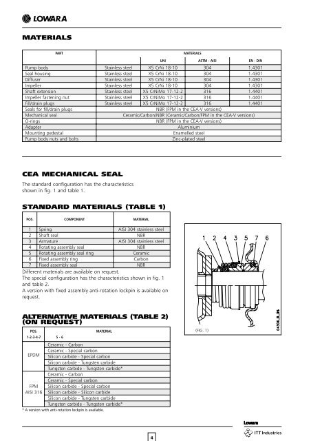
MATERIALS PART MATERIALS UNI ASTM - AISI EN - DIN Pump body Stainless steel X5 CrNi 18-10 304 1.4301 Seal housing Stainless steel X5 CrNi 18-10 304 1.4301 Diffuser Stainless steel X5 CrNi 18-10 304 1.4301 Impeller Stainless steel X5 CrNi 18-10 304 1.4301 Shaft extension Stainless steel X5 CrNiMo 17-12-2 316 1.4401 Impeller fastening nut Stainless steel X5 CrNiMo 17-12-2 316 1.4401 Fill/drain plugs Stainless steel X5 CrNiMo 17-12-2 316 1.4401 Seals for fill/drain plugs NBR (FPM in the <strong>CEA</strong>-V versions) Mechanical seal Ceramic/Carbon/NBR (Ceramic/Carbon/FPM in the <strong>CEA</strong>-V versions) O-rings NBR (FPM in the <strong>CEA</strong>-V versions) Adapter Aluminium Mounting pedestal Enamelled steel Pump body nuts and bolts Zinc-plated steel <strong>CEA</strong> MECHANI<strong>CA</strong>L SEAL The standard configuration has the characteristics shown in fig. 1 and table 1. STANDARD MATERIALS (TABLE 1) POS. COMPONENT MATERIAL 1 Spring AISI 304 stainless steel 2 Shaft seal NBR 3 Armature AISI 304 stainless steel 4 Rotating assembly seal NBR 5 Rotating assembly seal ring Ceramic 6 Fixed assembly ring Carbon 7 Fixed assembly seal NBR Different materials are available on request. The special configuration has the characteristics shown in fig. 1 and table 2. A version with fixed assembly anti-rotation lockpin is available on request. ALTERNATIVE MATERIALS (TABLE 2) (ON REQUEST) POS. 1-2-3-4-7 5 - 6 MATERIAL Ceramic - Carbon Ceramic - Special carbon EPDM Silicon carbide - Special carbon Silicon carbide - Tungsten carbide Tungsten carbide - Tungsten carbide* Ceramic - Carbon Ceramic - Special carbon FPM Silicon carbide - Special carbon AISI 316 Silicon carbide - Silicon carbide Silicon carbide - Tungsten carbide Tungsten carbide - Tungsten carbide* * A version with anti-rotation lockpin is available. (FIG. 1) 4
HYDRAULIC PERFORMANCE TABLE, <strong>CEA</strong>-<strong>CEA</strong>M <strong>SERIES</strong> 60 Hz PUMP TYPE RATED Q = DELIVERY POWER l/min 0 20 30 40 60 80 120 140 160 180 240 300 315 325 360 400 440 460 m 3 /h 0 1,2 1,8 2,4 3,6 4,8 7,2 8,4 9,6 10,8 14,4 18 18,9 19,5 21,6 24 26 28 kW HP H = TOTAL HEAD METERS COLUMN OF WATER <strong>CEA</strong>(M) 706/3 0,75 1 32,3 30,7 30,0 29,2 27,0 23,5 <strong>CEA</strong>(M) 706/4 0,9 1,2 39,2 37,5 36,6 35,7 33,4 28,7 <strong>CEA</strong>(M) 706/5 1,1 1,5 45,2 43,3 42,4 41,4 38,6 31,6 <strong>CEA</strong>(M) 1206/1 0,55 0,75 22,1 19,1 17,7 14,4 12,2 9,8 <strong>CEA</strong>(M) 1206/2 0,75 1 27,8 24,1 22,6 19,1 16,9 14,3 <strong>CEA</strong>(M) 1206/3 0,9 1,2 32,8 29,1 27,7 24,1 22,0 19,6 <strong>CEA</strong>(M) 1206/4 1,5 2 40,5 36,3 34,6 30,6 28,2 25,4 <strong>CEA</strong>(M) 1206/5 1,85 2,5 46,6 42,2 40,4 36,0 33,4 30,6 27,4 <strong>CEA</strong>(M) 2106/0 0,75 1 17,0 15,9 15,5 14,9 14,3 11,9 8,8 <strong>CEA</strong>(M) 2106/1 1,1 1,5 21,1 20,4 20,0 19,5 19,0 16,9 14,0 <strong>CEA</strong>(M) 2106/2 1,5 2 25,3 24,5 24,1 23,7 23,2 21,3 18,7 18,0 <strong>CEA</strong>(M) 2106/3 1,85 2,5 30,0 29,4 29,1 28,8 28,3 26,7 24,3 23,5 <strong>CEA</strong>(M) 2106/4 2,2 3 34,8 34,3 34,0 33,6 33,2 31,5 28,9 28,2 27,6 <strong>CEA</strong>(M) 3706/0 1,1 1,5 16,9 15,9 15,6 14,4 12,8 12,4 12,0 10,8 9,1 <strong>CEA</strong>(M) 3706/0A 1,5 2 19,8 19,4 19,2 18,4 17,2 16,8 16,5 15,4 13,8 11,9 <strong>CEA</strong>(M) 3706/1 1,85 2,5 23,5 22,9 22,6 21,7 20,3 19,9 19,6 18,5 17,1 15,4 14,5 cea-2p60-en_b_th PUMP TYPE INPUT INPUT <strong>CA</strong>PACITOR PUMP TYPE INPUT INPUT INPUT POWER* CURRENT* POWER* CURRENT* CURRENT* SINGLE-PHASE 220-230 V THREE-PHASE 220-230 V 380-400 V kW A µF / 450 V kW A A <strong>CEA</strong>M 706/3 0,96 4,39 20 <strong>CEA</strong> 706/3 0,89 2,93 1,69 <strong>CEA</strong>M 706/4 1,30 5,91 25 <strong>CEA</strong> 706/4 1,15 3,65 2,11 <strong>CEA</strong>M 706/5 1,54 7,13 30 <strong>CEA</strong> 706/5 1,40 4,17 2,41 <strong>CEA</strong>M 1206/1 0,84 3,87 16 <strong>CEA</strong> 1206/1 0,74 2,36 1,36 <strong>CEA</strong>M 1206/2 1,05 4,79 20 <strong>CEA</strong> 1206/2 0,99 3,14 1,81 <strong>CEA</strong>M 1206/3 1,39 6,31 25 <strong>CEA</strong> 1206/3 1,24 3,88 2,24 <strong>CEA</strong>M 1206/4 1,85 8,71 40 <strong>CEA</strong> 1206/4 1,70 5,09 2,94 <strong>CEA</strong>M 1206/5 2,23 10,6 40 <strong>CEA</strong> 1206/5 2,05 6,26 3,62 <strong>CEA</strong>M 2106/0 1,06 4,85 20 <strong>CEA</strong> 2106/0 1,00 3,17 1,83 <strong>CEA</strong>M 2106/1 1,50 6,98 30 <strong>CEA</strong> 2106/1 1,37 4,09 2,36 <strong>CEA</strong>M 2106/2 1,90 8,87 40 <strong>CEA</strong> 2106/2 1,75 5,21 3,01 <strong>CEA</strong>M 2106/3 2,29 10,8 40 <strong>CEA</strong> 2106/3 2,12 6,43 3,71 <strong>CEA</strong>M 2106/4 3,02 14,2 40 <strong>CEA</strong> 2106/4 2,86 8,35 4,82 <strong>CEA</strong>M 3706/0 1,54 7,15 30 <strong>CEA</strong> 3706/0 1,41 4,19 2,42 <strong>CEA</strong>M 3706/0A 1,97 9,19 40 <strong>CEA</strong> 3706/0A 1,84 5,44 3,14 <strong>CEA</strong>M 3706/1 2,51 11,7 40 <strong>CEA</strong> 3706/1 2,35 7,00 4,04 * Maximum value in specified range cea-2p60-en_b_te IDENTIFI<strong>CA</strong>TION CODE The <strong>CEA</strong>M-<strong>CEA</strong> models are identified as shown in the following table. C E A M 1 2 0 6 / 5 – V FPM version Impeller size 60 Hz Flow rate in l/min. Single-phase version Series 5