FHWS Science Journal - Fakultät Informatik und Wirtschaftsinformatik
FHWS Science Journal - Fakultät Informatik und Wirtschaftsinformatik
FHWS Science Journal - Fakultät Informatik und Wirtschaftsinformatik

Create successful ePaper yourself
Turn your PDF publications into a flip-book with our unique Google optimized e-Paper software.
Tobias Gegner<br />
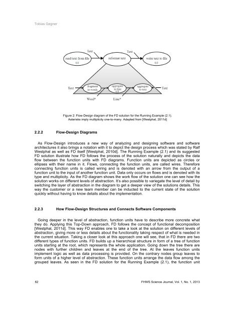
Figure 2: Flow-Design diagram of the FD solution for the Running Example (2.1).<br />
Asterisks imply multiplicity one-to-many. Adapted from [Westphal, 2011d]<br />
2.2.2 Flow-Design Diagrams<br />
As Flow-Design introduces a new way of analyzing and designing software and software<br />
architectures it also brings a notation with it to depict the design process which was stated by Ralf<br />
Westphal as well as FD itself [Westphal, 2010d]. The Running Example (2.1) and its suggested<br />
FD solution illustrate how FD follows the process of the solution naturally and depicts the data<br />
flow between the function units with FD diagrams. Function units are depicted as circles or<br />
ellipses with their name in it. Flows, connecting the function units, are called wires. Therefore<br />
connecting function units is called wiring and is denoted with an arrow from the output of a<br />
function unit to the input of another function unit. Data only occurs on flows and is denoted with its<br />
type and multiplicity. As the FD diagram shows the work flow of the solution one can see how the<br />
solution works on different levels of abstraction. It’s also possible to variegate the level of detail by<br />
switching the layer of abstraction in the diagram to get a deeper view of the solutions details. This<br />
way the customer or a new team member can be inducted to the current state of the solution<br />
quickly without having to know details about the implementation.<br />
2.2.3 How Flow-Design Structures and Connects Software Components<br />
Going deeper in the level of abstraction, function units have to describe more concrete what<br />
they do. Applying this Top-Down approach, FD follows the concept of functional decomposition<br />
[Westphal, 2011d]. This way FD enables one to take a look at the solution on different levels of<br />
abstraction, giving more or less details about the functionality taking respect of what is needed in<br />
the current situation. Taking a closer look at this approach one will see, that in FD there are two<br />
different types of function units. FD builds up a hierarchical structure in form of a tree of function<br />
units starting at the root, which represents the whole application. Going down the tree there are<br />
nodes with further children and leaves at the end of the tree. At the leaves function units<br />
implement logic as well as data processing is provided. On the contrary nodes group leaves to<br />
form units of a higher level of abstraction. These function units arrange the data flow among the<br />
grouped leaves. As seen in the FD solution for the Running Example (2.1), the function unit<br />
62 <strong>FHWS</strong> <strong>Science</strong> <strong>Journal</strong>, Vol. 1, No. 1, 2013