Owners Manual - HKTS 20, HKTS 30 (English EU
Owners Manual - HKTS 20, HKTS 30 (English EU
Owners Manual - HKTS 20, HKTS 30 (English EU

You also want an ePaper? Increase the reach of your titles
YUMPU automatically turns print PDFs into web optimized ePapers that Google loves.
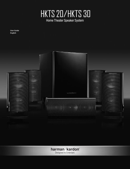
<strong>HKTS</strong> <strong>20</strong>/<strong>HKTS</strong> <strong>30</strong><br />
Home Theater Speaker System<br />
User Guide<br />
<strong>English</strong><br />
Designed to Entertain.
Important Safety Instructions<br />
Please read the following precautions before use:<br />
1. Read these instructions.<br />
2. Keep these instructions.<br />
3. Heed all warnings.<br />
4. Follow all instructions.<br />
5. Do not use this apparatus near water.<br />
6. Clean only with a dry cloth.<br />
7. Do not block any ventilation openings. Install in accordance with the manufacturer’s<br />
instructions.<br />
8. Do not install near any heat sources such as radiators, heat registers, stoves or other<br />
apparatus (including amplifiers) that produce heat.<br />
9. Do not defeat the safety purpose of the polarized or grounding-type plug. A polarized<br />
plug has two blades with one wider than the other. A grounding-type plug has two blades<br />
and a third grounding prong. The wide blade or the third prong is provided for your safety. If<br />
the provided plug does not fit into your outlet, consult an electrician for replacement of the<br />
obsolete outlet.<br />
10. Protect the power cord from being walked on or pinched, particularly at plugs,<br />
convenience receptacles and the point where they exit from the apparatus.<br />
11. Only use attachments/accessories specified by the manufacturer.<br />
12. Use only with the cart, stand, tripod, bracket or table specified by<br />
the manufacturer or sold with the apparatus. When a cart is used, use<br />
caution when moving the cart/apparatus combination to avoid injury<br />
from tip-over.<br />
13. Unplug this apparatus during lightning storms or when unused for long periods of time.<br />
14. Refer all servicing to qualified service personnel. Servicing is required when the<br />
apparatus has been damaged in any way, such as power supply cord or plug is damaged,<br />
liquid has been spilled or objects have fallen into the apparatus, the apparatus has been<br />
exposed to rain or moisture, does not operate normally, or has been dropped.<br />
15. Do not expose this apparatus to dripping or splashing and ensure that no objects filled<br />
with liquids, such as vases, are placed on the apparatus.<br />
16. To completely disconnect this apparatus from the AC Mains, disconnect the power<br />
supply cord plug from the AC receptacle.<br />
17. The mains plug of the power supply cord shall remain readily operable.<br />
18. Do not expose batteries to excessive heat such as sunshine, fire or the like.<br />
The lightning flash with arrowhead symbol, within an equilateral triangle,<br />
is intended to alert the user to the presence of uninsulated “dangerous<br />
voltage” within the product’s enclosure that may be of sufficient magnitude<br />
to constitute a risk of electric shock to persons.<br />
The exclamation point within an equilateral triangle is intended to alert the<br />
user to the presence of important operating and maintenance (servicing)<br />
instructions in the literature accompanying the product.<br />
WARNING: To reduce the risk of fire or electric shock,<br />
do not expose this apparatus to rain or moisture.<br />
Pb<br />
Instructions for users on removal and disposal of used batteries.<br />
Specification of included battery types.<br />
These symbols shown on the product, the packaging or in the manual or separate information<br />
sheet mean that the product itself, as well as the batteries included or built into the<br />
product, should never be thrown away with general household waste. Take them to applicable<br />
collection points, where proper treatment, recycling and recovery takes place, in accordance<br />
with national or local legislation, or European Directives <strong>20</strong>02/96/EC and <strong>20</strong>06/66/EC.<br />
Correct handling of the product and batteries to be disposed helps save resources and prevents<br />
possible negative effects on the environment or human health.<br />
The batteries included with your equipment may be Alkaline, Carbon Zinc/Manganese or<br />
Lithium (button cells) type. All types should be disposed of according to the above instructions.<br />
To remove the batteries from your equipment or remote control, reverse the procedure<br />
described for inserting batteries in the <strong>Owners</strong> <strong>Manual</strong>.<br />
For products with a built-in battery that lasts for the lifetime of the product, removal may not<br />
be possible for the user. In this case, recycling or recovery centers handle the dismantling of<br />
the product and the removal of the battery. If, for any reason, it becomes necessary to replace<br />
such a battery, this procedure must be performed by authorized service centers.<br />
Declaration of Conformity<br />
We, Harman Consumer, Consumer Division<br />
8500 Balboa Blvd.<br />
Northridge, CA 91329<br />
USA<br />
As the manufacturer and through our representative<br />
within the <strong>EU</strong><br />
Harman Consumer, Consumer Division<br />
2, route de Tours<br />
72500 Chateau du Loir<br />
France<br />
Do declare under our sole responsibility that the product listed<br />
below conforms to the requirements of the Directive(s) and<br />
Standards listed here in.<br />
Model(s): <strong>HKTS</strong><strong>20</strong> and <strong>HKTS</strong><strong>30</strong><br />
Directives to which Conformity is declared:<br />
<strong>20</strong>04/108/EC – EMC Directive, as amended.<br />
1999/5EC – R&TTE Directive, as amended.<br />
<strong>20</strong>06/95/EC – Low Voltage Directive, as amended<br />
<strong>20</strong>05/32/EC – Energy Using Products Directive, as amended<br />
Harmonized Standards Applied to show Conformity:<br />
EN 55013:<strong>20</strong>01+A1:<strong>20</strong>03+A2:<strong>20</strong>06<br />
EN 550<strong>20</strong>:<strong>20</strong>07<br />
EN 61000-3-2:<strong>20</strong>06<br />
EN 61000-3-3:1995+A1:<strong>20</strong>01+A2:<strong>20</strong>05<br />
EN 60065:<strong>20</strong>02+A11:<strong>20</strong>08<br />
EN 60825-1:<strong>20</strong>07<br />
ETSI EN <strong>30</strong>0 328 V1.7.1 (<strong>20</strong>06-10)<br />
ETSI EN <strong>30</strong>1 489-1 V1.8.1 (<strong>20</strong>08-04)<br />
Laurent Rault<br />
Harman Consumer Group, Inc.<br />
Château du Loir, France 10/09<br />
THE LIGHTNING<br />
FLASH AND<br />
ARROWHEAD WITHIN<br />
THE TRIANGLE IS<br />
A WARNING SIGN<br />
ALERTING YOU TO<br />
DANGEROUS VOLTAGE<br />
INSIDE THE PRODUCT.<br />
CAUTION<br />
RISK OF ELECTRIC SHOCK<br />
DO NOT OPEN<br />
CAUTION: TO REDUCE THE RISK OF<br />
SHOCK, DO NOT REMOVE COVER.<br />
NO USER-SERVICEABLE PARTS<br />
INSIDE. REFER SERVICING TO<br />
QUALIFIED SERVICE PERSONNEL.<br />
SEE MARKING ON BACK OF PRODUCT.<br />
THE EXCLAMATION<br />
POINT WITHIN<br />
THE TRIANGLE IS<br />
A WARNING SIGN<br />
ALERTING YOU<br />
TO IMPORTANT<br />
INSTRUCTIONS<br />
ACCOMPANYING THE<br />
PRODUCT.<br />
ATTENTION!<br />
It is considered good practice to always connect the power<br />
supply to your Harman Kardon unit before plugging<br />
the device into the wall or AC power outlet.<br />
Important Note for All Electronic Products:<br />
Before inserting or unplugging audio cables from the source device’s<br />
headphones or line-level output jacks, it is good practice to turn off the device<br />
first. This will prolong the life of your unit, help protect your device from static<br />
electricity and prevent potential damage.<br />
WARNING: TO PREVENT FIRE OR ELECTRICAL SHOCK HAZARD, DO NOT EXPOSE THIS PRODUCT<br />
TO RAIN OR MOISTURE.<br />
WARNING: THE APPARATUS SHOULD NOT BE EXPOSED TO DRIPPING OR SPLASHING AND NO<br />
OBJECTS FILLED WITH LIQUID, SUCH AS VASES, SHOULD BE PLACED ON THE APPARATUS.<br />
Harman Kardon® <strong>HKTS</strong> <strong>20</strong> / <strong>HKTS</strong> <strong>30</strong><br />
Typographical Conventions<br />
We have employed certain conventions to help you use this manual:<br />
– (number in a circle) – Indicates a rear-panel control or connection on the illustration of the <strong>HKTS</strong><strong>20</strong>0SUB subwoofer<br />
Example (bold type) – Indicates the name of a specific control or rear-panel connection on the <strong>HKTS</strong><strong>20</strong>0SUB subwoofer<br />
EXAMPLE (OCR type) – Indicates a control or switch setting on the <strong>HKTS</strong><strong>20</strong>0SUB subwoofer<br />
2
Harman Kardon®<br />
<strong>HKTS</strong> <strong>20</strong> / <strong>HKTS</strong> <strong>30</strong><br />
Introduction<br />
Thank you for purchasing the Harman Kardon ® <strong>HKTS</strong><strong>20</strong>/<strong>HKTS</strong><strong>30</strong> speaker system, with<br />
which you’re about to begin many years of listening enjoyment. The <strong>HKTS</strong><strong>20</strong>/<strong>HKTS</strong><strong>30</strong> has<br />
been custom designed to provide all the excitement and power of the cinema experience<br />
in your own living room.<br />
While sophisticated electronics and state-of-the-art speaker components are hard at work<br />
within the <strong>HKTS</strong><strong>20</strong> and <strong>HKTS</strong><strong>30</strong>, hookup and operation are simple. Color-keyed cables and<br />
connections, and simple controls make the <strong>HKTS</strong><strong>20</strong>/<strong>HKTS</strong><strong>30</strong> easy to use.<br />
To obtain maximum enjoyment from your new home theater speaker system, we urge<br />
you to take a few minutes to read through this manual. This will help ensure that the<br />
connections you make to your receiver (or preamp/processor), amplifier and other devices<br />
are correct. In addition, a few minutes spent learning the functions of the various controls<br />
will enable you to take advantage of all the power and refinement the <strong>HKTS</strong><strong>20</strong>/<strong>HKTS</strong><strong>30</strong> is<br />
able to deliver.<br />
If you have any questions about this product, its installation or its operation, please<br />
contact your dealer, the best local source of information.<br />
Description and Features<br />
The <strong>HKTS</strong><strong>20</strong>/<strong>HKTS</strong><strong>30</strong> is a complete six-piece home theater speaker system that includes:<br />
•• An 8-inch, <strong>20</strong>0-watt powered subwoofer<br />
•• Four identical two-way video-shielded satellite speakers (the <strong>HKTS</strong><strong>30</strong> satellite<br />
speakers feature dual drivers) for the left and right front, and left and right rear<br />
(surround) speaker positions<br />
•• A dedicated, voice-matched, video-shielded, dual-driver center speaker<br />
•• Removable bases and wall-mount brackets for the satellite speakers and a wallmount<br />
bracket for the center speaker<br />
•• All of the cables you need to connect all of the speakers to your receiver or preamp/<br />
processor and amplifier.<br />
The speaker cables all use a color-coding system to conform to the Consumer Electronics<br />
Association (CEA) standard. This color-coding system minimizes confusion when<br />
connecting the speakers, especially when you are connecting them to a Harman Kardon<br />
receiver.<br />
The <strong>HKTS</strong><strong>20</strong>0SUB subwoofer is equipped with a special LFE input that simplifies<br />
connection to receivers and preamp/processors with dedicated subwoofer outputs that<br />
carry low-frequency signals. Other conveniences include a level control, a phase switch for<br />
fine-tuning bass response to suit your listening environment and taste, and an efficient<br />
switching system that senses the presence of an audio signal and automatically switches<br />
the subwoofer from standby mode to on.<br />
Wall-mount brackets are included for the satellite and center speakers, and shelf stands<br />
are included for the satellite speakers. Optional HKFS3 floorstands are available separately<br />
from your Harman Kardon dealer. Harman Kardon invented the high-fidelity receiver fifty<br />
years ago. With state-of-the-art features and time-honored circuit designs, the <strong>HKTS</strong><strong>20</strong>/<br />
<strong>HKTS</strong><strong>30</strong> is a perfect complement to a Harman Kardon receiver, or any home theater<br />
system.<br />
Included<br />
Four satellite speakers for front left/right and surround left/right<br />
(<strong>HKTS</strong><strong>30</strong> satellites shown)<br />
One powered subwoofer<br />
One wall-mount bracket for<br />
center speaker<br />
Four wall-mount brackets for satellite<br />
speakers<br />
Four metal stop plates and screws<br />
(for satellite speaker wall-mount brackets)<br />
One combination LFE and trigger cable for<br />
connection to the subwoofer<br />
(LFE cable has purple connectors)<br />
One 4-meter (13.1-foot) speaker cable for<br />
center speaker (green color bands)<br />
Two 5-meter (16.4-foot) speaker cables for<br />
front satellites (red and white color bands)<br />
ENGLISH<br />
Two 10-meter (32.8-foot) speaker cables for<br />
rear satellites<br />
(gray and blue color bands)<br />
3
PL0004-01001<br />
<strong>HKTS</strong><strong>20</strong>0SUB Rear-Panel Connections<br />
1<br />
2<br />
3<br />
4<br />
5<br />
6<br />
7<br />
8<br />
9<br />
0. Subwoofer Level Control: Use this control to adjust the <strong>HKTS</strong><strong>20</strong>0SUB’s volume. Turn<br />
clockwise to increase the volume; turn counterclockwise to decrease the volume.<br />
1. Bass Boost Switch: Set this switch to ON to enhance the <strong>HKTS</strong><strong>20</strong>0SUB’s low-frequency<br />
performance. Set this switch to OFF for normal low-frequency performance.<br />
2. Phase Switch: The Phase Switch 2 determines whether the <strong>HKTS</strong><strong>20</strong>0SUB’s piston-like<br />
action moves in and out in phase with the satellite speakers. If the subwoofer were<br />
to play out of phase with the satellite speakers, the sound waves produced by the<br />
subwoofer could be canceled out, reducing bass performance and sonic impact. This<br />
phenomenon depends in part on the relative placement of all the speakers in the<br />
room. In most cases the Phase Switch 2 should be left in the NORMAL position.<br />
However, it does no harm to experiment, and you can leave the Phase Switch 2 in<br />
the position that maximizes bass response and impact.<br />
3. Power On Mode Switch: When set in the AUTO position and when the Power Switch<br />
7 is set to ON, the <strong>HKTS</strong><strong>20</strong>0SUB will automatically turn itself on when it receives an<br />
audio signal, and will enter the standby mode once no audio signal has been received<br />
for about 15 minutes. When this switch is set in the ON position, the <strong>HKTS</strong><strong>20</strong>0SUB<br />
will remain on whether or not it is receiving an audio signal.<br />
An LED on the <strong>HKTS</strong><strong>20</strong>0SUB’s top panel indicates whether the subwoofer is in the on<br />
or standby state:<br />
• When the LED is illuminated white, the <strong>HKTS</strong><strong>20</strong>0SUB is turned on.<br />
• When the LED is not illuminated, the <strong>HKTS</strong><strong>20</strong>0SUB is in standby mode.<br />
When the Master Power Switch 7 is set to OFF, the LED will not be<br />
illuminated, no matter what setting the Power On Mode Switch 3 is in.<br />
4. External Trigger Input: Use the mini-plug of the supplied combination LFE and trigger<br />
cable to connect the External Trigger Input to the trigger output of another<br />
compatible component. Whenever a trigger signal between 3 and <strong>30</strong>V (AC or DC) is<br />
detected, the <strong>HKTS</strong><strong>20</strong>0SUB’s amplifier will turn on. The <strong>HKTS</strong><strong>20</strong>0SUB’s amplifier will<br />
turn off after the trigger signal ceases. (This will occur even when the Power On<br />
Mode Switch 3 is in the AUTO position.)<br />
5. Line-Level LFE In Connector: Use the LFE (purple) connector of the supplied combination<br />
LFE and trigger cable to connect the Line-Level LFE In to the dedicated subwoofer<br />
output of a receiver or preamp/processor. This input bypasses the <strong>HKTS</strong><strong>20</strong>0SUB’s<br />
internal crossover circuitry, so it should only be used with a subwoofer output that has<br />
been low-pass filtered. If your receiver or preamp/processor does not have a dedicated<br />
subwoofer output that is low-pass filtered you should use the <strong>HKTS</strong><strong>20</strong>0SUB’s Line-<br />
Level L/R In Connectors 6 instead.<br />
6. Line-Level L/R In Connectors: Use these connectors if your receiver or preamp/processor<br />
does not have digital surround sound decoding or a subwoofer output that is low-pass<br />
filtered.<br />
• If your receiver or preamp/processor has a separate subwoofer output, use the LFE<br />
(purple) connector of the supplied combination LFE and trigger cable to connect it to<br />
either one of the <strong>HKTS</strong><strong>20</strong>0SUB’s Line-Level L/R In Connectors.<br />
• If your receiver or preamp/processor does not have a separate subwoofer output,<br />
use two Y-adapters (not supplied). Connect an adapter’s single end to the unit’s<br />
preamp output for that channel. Connect one of the adapter’s dual ends to the main<br />
amp input for that channel, and connect the adapter’s other dual end to one of the<br />
<strong>HKTS</strong><strong>20</strong>0SUB’s Line-Level L/R In Connectors. Repeat with the other Y-adapter,<br />
preamp channel, main amp input and <strong>HKTS</strong><strong>20</strong>0SUB Line-Level L/R In Connector.<br />
7. Power Switch: Set this switch in the ON position to turn the <strong>HKTS</strong><strong>20</strong>0SUB on. The<br />
subwoofer will then either be on or in standby mode, depending on the setting of the<br />
Power On Mode Switch 3.<br />
8. Power Cord (Non-Detachable): After you have made and verified all subwoofer<br />
and speaker connections described in this manual, plug this cord into an active,<br />
unswitched electrical outlet for proper operation of the <strong>HKTS</strong><strong>20</strong>0SUB. DO NOT plug this<br />
cord into the accessory outlets found in some audio components.<br />
4
Speaker Placement<br />
NOTE: The following speaker placement, mounting and connection instructions are<br />
identical for the <strong>HKTS</strong><strong>20</strong> and <strong>HKTS</strong><strong>30</strong> systems.<br />
Color-Coding System<br />
The <strong>HKTS</strong><strong>20</strong> and <strong>HKTS</strong><strong>30</strong> use the channel color-coding system established by the CEA<br />
to make setting up your home theater speaker system as easy as possible. The <strong>HKTS</strong><strong>20</strong>/<br />
<strong>HKTS</strong><strong>30</strong> systems include speaker wires with color bands on each end.<br />
Speaker Position Wire Color Band<br />
Front Left<br />
White<br />
Front Right<br />
Red<br />
Center<br />
Green<br />
Surround Left<br />
Blue<br />
Surround Right Gray<br />
Subwoofer<br />
Purple<br />
0 – 2ft<br />
Placing the Front Speakers<br />
Left Front<br />
Speaker<br />
Right Front<br />
Speaker<br />
Placing the Center Speaker<br />
Left Front<br />
Speaker<br />
Center<br />
Speaker<br />
0 - 2 ft<br />
(0 - 61cm)<br />
Right Front<br />
Speaker<br />
Placing the Subwoofer<br />
Left Front<br />
Speaker<br />
Right Front<br />
Speaker<br />
Subwoofer<br />
The front speakers should be placed the same<br />
distance from each other as they are from the<br />
listening position. They should be placed at about<br />
the same height from the floor as the listener’s<br />
ears will be. They also can be angled toward the<br />
listener.<br />
The center speaker should be placed slightly<br />
behind (farther away from the listener) the front<br />
left and right speakers. Its center should be no<br />
more than 2 feet (61cm) above or below the<br />
tweeters of the front left and right speakers. If you<br />
have a CRT television, it may be convenient to set<br />
the center speaker on top of the television set.<br />
Since our ears do not hear directional sound<br />
at the low frequencies where the subwoofer<br />
operates, it will have good performance from<br />
just about any location in your room. However,<br />
the best bass reproduction is likely to be heard<br />
when the subwoofer is placed in a corner along<br />
the same wall as the front left and right speakers.<br />
You can experiment with subwoofer placment<br />
by temporarily placing it in the listening position<br />
and playing music with strong bass content. Move<br />
around to various locations in the room while<br />
the system is playing and listen until you find the<br />
location where the bass performance is best. Place<br />
the subwoofer in that location.<br />
The two surround speakers should be placed slightly behind the listening position, facing<br />
each other and, ideally, should be 5–6 feet (1.5m–1.8m) from the floor. An alternate<br />
location would be on a wall behind the listening position, facing forward. The surround<br />
speakers should not call attention to themselves while they’re playing.<br />
Experiment with their placement until you hear a diffuse, ambient sound accompanying<br />
the program material heard from the front left and right and center speakers.<br />
Mounting Options for Satellite and Center<br />
Speakers<br />
Shelf Placement<br />
You can place the satellite and center speakers<br />
on shelves. The satellite speakers have built-in<br />
bases for shelf placement. You can also remove<br />
the bases if desired.<br />
To remove a satellite speaker’s base, pull<br />
it straight off the speaker, as shown in the<br />
illustration. Applying even pressure to both sides<br />
of the base will allow it to slide off smoothly.<br />
Wall-Mounting: Satellite Speakers<br />
IMPORTANT: Read the Speaker Connections<br />
section, on page 7, before wall-mounting the<br />
satellite speakers. You will need to insert the<br />
speaker wires through the wall mounts and<br />
connect the wires to the speakers during the<br />
process of installing the wall-mounts.<br />
NOTE: If you are using your own speaker wire, it must<br />
be no thicker than the wire supplied with the speakers. Thicker<br />
wire will prevent the wall-mount bracket from sliding onto the<br />
speaker.<br />
1. Decide on the location for the speaker<br />
(see Speaker Placement, opposite).<br />
2. Remove the speaker’s base as explained in Shelf Placement, above.<br />
3. Disassemble the wall-mount bracket by sliding the two sections apart, as shown in the<br />
illustration.<br />
4. Attach the wall portion of the wall-mount onto the wall using hardware that is<br />
appropriate for the wall’s construction and materials. We recommend first anchoring<br />
the mount using its keyhole, then attaching it with another anchor through its top<br />
opening, as shown in the illustration. Note that the satellite speakers weigh 3.3 lb<br />
(1.5kg). Be sure to use hardware that can support this weight.<br />
Top Opening<br />
Keyhole Opening<br />
Bottom Opening<br />
Apply Pressure Evenly<br />
to Both Sides of Base<br />
Lift Base Straight<br />
off Speaker<br />
Pull Sections<br />
Apart<br />
ENGLISH<br />
Placing the Surround Speakers<br />
Left Surround<br />
Sound<br />
Right Surround<br />
Sound<br />
Left Front<br />
Speaker<br />
Center<br />
Speaker<br />
Right Front<br />
Speaker<br />
Subwoofer<br />
5 - 6 ft<br />
(1.5m - 1.8m)<br />
Left Surround<br />
Sound<br />
Right Surround<br />
Sound<br />
5
NOTE: If you’re running the speaker wire through the wall you can bring it out directly<br />
behind the bracket location and insert it through the bottom opening in the wall portion<br />
of the wall-mount, as shown in the illustration. This will keep the wire completely hidden<br />
from view once the installation is complete.<br />
8. Connect the speaker wire to the speaker terminals as shown in the illustration:<br />
a) Press down on the top of the terminal to open the connection hole.<br />
b) Insert the wire’s bare end all the way into the hole.<br />
c) Release the terminal to secure the wire.<br />
Insert the conductor with the colored band into the speaker’s red ( + ) terminal, and<br />
insert the other conductor into the speaker’s black ( – ) terminal.<br />
Insert Wire into<br />
Bottom Opening<br />
Bring Wire Out<br />
through Here<br />
+ –<br />
5.<br />
If you’re not running the speaker wire through the wall, insert it through the wall portion<br />
of the wall-mount bracket as shown in the illustration.<br />
A. Push Down on Cap to<br />
Open Hole<br />
B. Insert Bare Wire into<br />
Open Hole<br />
C. Release Cap to Secure Wire<br />
9.<br />
IMPORTANT: Make sure the ( + ) and ( – ) bare wires do not touch each other or the<br />
other terminal. Touching wires can cause a short circuit that can damage your receiver<br />
or amplifier.<br />
Slide the speaker portion of wall-mount onto the speaker as shown in the illustration. Fit<br />
the grooves on the mount onto the rails in the speaker, and apply even pressure on<br />
both sides of the mount so it slides straight onto the speaker.<br />
• Push the mount all the way onto the speaker until it snaps into place.<br />
• Pull any slack speaker wire back through the mount as you slide the mount onto the<br />
speaker.<br />
Push Down Evenly on Both Sides of Bracket<br />
6.<br />
Pass the speaker wire through the speaker portion of the wall-mount as shown in the<br />
illustration.<br />
Fit Bracket Grooves<br />
onto Speaker Rails<br />
Bring Wire In<br />
through Here<br />
Bring Wire Out<br />
through Here<br />
10. Slide the speaker onto the mount’s wall section as shown in the illustration. Pull any slack<br />
speaker wire back through the mount’s wall section.<br />
7. If you have not already removed the speaker’s base, do so by pulling it straight off the<br />
speaker, as shown in the illustration. Applying even pressure to both sides of the base<br />
will allow it to slide off smoothly.<br />
Slide Speaker<br />
onto Wall-Mount<br />
Apply Pressure Evenly<br />
to Both Sides of Base<br />
Lift Base Straight<br />
off Speaker<br />
11. Fit the metal stop plate into the recess on the bottom of the mount with the pad facing<br />
the mount, and fasten it to the mount using two of the supplied screws. This will<br />
prevent The speaker from detaching from the bracket and will hold the speaker’s<br />
position as you rotate it on the mount.<br />
CAUTION: Before making speaker connections, be sure that your receiver or amplifier<br />
is turned OFF and preferably, its AC cord is unplugged from the AC outlet.<br />
Stop Plate<br />
Supplied Screws<br />
6
Wall-Mounting: Center Speaker<br />
1. Decide on the location for the speaker (see Speaker Placement, on page 5).<br />
2. Attach the center speaker wall-mount bracket to the wall using hardware that is<br />
appropriate for the wall’s construction and materials. Attach the anchors through the<br />
holes shown in the illustration.<br />
Use These Holes<br />
to Attach Bracket<br />
to Wall<br />
NOTE: The center speaker weighs 3.2 lb (1.45kg). Be sure to use hardware that can<br />
support this weight.<br />
CAUTION: Before making speaker connections, be sure that your receiver or amplifier is<br />
turned OFF and preferably, its AC cord is unplugged from the AC power source.<br />
3. Connect the speaker wire to the speaker terminals. Press down on the top of the terminal<br />
to open the connection hole, insert the wire’s bare end all the way into the hole and<br />
release the terminal to secure the wire. Insert the conductor with the colored band<br />
into the speaker’s red ( + ) terminal, and insert the other conductor into the speaker’s<br />
black ( – ) terminal, as shown in the illustration.<br />
A. Push Down on Cap to<br />
Open Hole<br />
B. Insert Bare Wire into<br />
Open Hole<br />
C. Release Cap to Secure Wire<br />
Speakers and receivers/amplifiers have corresponding ( + ) and ( – ) connection<br />
terminals. Most electronics manufacturers, including Harman Kardon, use red to denote<br />
the ( + ) terminal and black for the ( – ) terminal. Newer Harman Kardon receivers<br />
conform to the CEA standard and therefore use a color other than red to denote the ( + )<br />
terminal for some speaker positions. See the table in Color-Coding System, on page 5.<br />
Each speaker wire included with your system has colored bands at both ends of the ( + )<br />
conductor, and the subwoofer cable has purple connectors that correspond to the color of<br />
the <strong>HKTS</strong><strong>20</strong>0SUB’s LFE jack. This system helps ensure that the speaker in each location is<br />
connected to the correct receiver or amplifier terminals. In addition to the colored bands<br />
at each end, each speaker wire’s ( + ) terminal has ribs molded into its insulation to help<br />
identify it.<br />
It is very important to connect each speaker identically: ( + ) on the speaker to ( + ) on<br />
the receiver or amplifier, and ( – ) on the speaker to ( – ) on the receiver or amplifier.<br />
Miswiring one or more speakers results in thin sound, weak bass and a poor stereo<br />
image. With the advent of multichannel surround-sound systems, connecting all of the<br />
speakers in your system correctly is very important to achieving the proper ambience and<br />
directionality of the program material.<br />
To connect the speaker wire to the terminals on the satellite and center speakers, press<br />
down on the top of the terminal to open the connection hole, insert the wire’s bare end<br />
all the way into the hole and release the terminal to secure the wire. Insert the conductor<br />
with the colored band into the speaker’s red ( + ) terminal, and insert the other conductor<br />
into the speaker’s black ( – ) terminal, as shown in the illustration.<br />
ENGLISH<br />
+ –<br />
+ –<br />
4.<br />
Important: Make sure the ( + ) and ( – ) bare wires do not touch each other or the<br />
other terminal. Touching wires can cause a short circuit that can damage your receiv<br />
er or amplifier.<br />
Using two of the supplied screws, attach the center speaker to the wall-mount<br />
bracket, as shown in the illustration.<br />
A. Push Down on Cap to<br />
Open Hole<br />
B. Insert Bare Wire into<br />
Open Hole<br />
C. Release Cap to Secure Wire<br />
IMPORTANT: Make sure the ( + ) and ( – ) bare wires do not touch each other or the<br />
other terminal. Touching wires can cause a short circuit that can damage your receiver or<br />
amplifier.<br />
Wall-Mount<br />
Bracket<br />
Supplied Screws<br />
Connecting Satellite Speakers With Supplied<br />
Wall-Mount Brackets<br />
Follow the instructions in Wall-Mounting: Satellite Speakers, on page 5, and<br />
Wall-Mounting: Center Speaker, opposite.<br />
Connecting Satellite Speakers with Supplied Bases<br />
1. Remove the speaker’s base (see Shelf Placement, on page 5).<br />
2. Pass the speaker wire through the opening in the speaker base.<br />
3. Connect the speaker wire as described above.<br />
4. Reattach the speaker’s base as shown in the illustration.<br />
Speaker Connections<br />
CAUTION: Before making speaker connections, be sure that your receiver or amplifier is<br />
turned OFF and preferably, its AC cord is unplugged from the AC power outlet.<br />
7
PL0004-01001<br />
Left Front<br />
Center<br />
Right Front<br />
Front Left<br />
Speaker Cable<br />
(White Bands)<br />
Center<br />
Speaker Cable<br />
(Green Bands)<br />
Front Right<br />
Speaker Cable<br />
(Red Bands)<br />
–<br />
+<br />
–<br />
+<br />
–<br />
+<br />
FRONT<br />
+ – + –<br />
RIGHT<br />
SURROUND<br />
+ –<br />
CENTER<br />
+ –<br />
LEFT<br />
+ –<br />
SUB<br />
LFE OUT<br />
Receiver<br />
Subwoofer<br />
Surround Left<br />
Speaker Cable<br />
(Blue Bands)<br />
LFE/Trigger Cable<br />
(Purple Ends)<br />
PL0004-01001<br />
Surround Right<br />
– +<br />
– +<br />
Speaker Cable<br />
(Gray Bands)<br />
Left<br />
Surround<br />
Right<br />
Surround<br />
Connecting the Subwoofer to a Receiver or Preamp/Processor With a Dedicated Subwoofer Output<br />
Use this installation method for receivers and preamp/processors that have a dedicated<br />
subwoofer output with low-pass filtering (also called bass management). If the dedicated<br />
subwoofer output does not have low-pass filtering, follow the instructions in Connecting<br />
the Subwoofer to a Receiver or Preamp/Processor With Line Outputs, on page 9.<br />
Use the LFE (purple) connector of the supplied combination LFE and trigger cable to<br />
connect the <strong>HKTS</strong><strong>20</strong>0SUB’s Line-Level LFE In Jack 5 to the dedicated subwoofer output<br />
(or LFE output) of your receiver or preamp/processor.<br />
Connect each satellite speaker and the center speaker to the corresponding speaker<br />
terminals on your receiver or amplifier.<br />
In your receiver or preamp/processor’s setup menu, configure it for Subwoofer ON, and<br />
set the front left, front right, center, and surround speakers to Small. After you have made<br />
and verified all connections, plug the <strong>HKTS</strong><strong>20</strong>0SUB’s AC Power Cord 8 into an active AC<br />
outlet.<br />
8
PL0004-01001<br />
Left Front<br />
Center<br />
Right Front<br />
ENGLISH<br />
Front Left<br />
Speaker Cable<br />
(White Bands)<br />
Center<br />
Speaker Cable<br />
(Green Bands)<br />
Front Right<br />
Speaker Cable<br />
(Red Bands)<br />
–<br />
+<br />
–<br />
+<br />
–<br />
+<br />
FRONT<br />
+ – + –<br />
RIGHT<br />
SURROUND<br />
+ –<br />
CENTER<br />
+ –<br />
LEFT<br />
+ –<br />
LINE-LEVEL<br />
OUTPUTS<br />
L R<br />
Receiver<br />
Subwoofer<br />
Surround Left<br />
Speaker Cable<br />
(Blue Bands)<br />
RCA Cable<br />
(Not Supplied)<br />
(Red and White Ends)<br />
PL0004-01001<br />
Surround<br />
– +<br />
Speaker Cable<br />
Right<br />
– +<br />
(Gray Bands)<br />
Left<br />
Surround<br />
Right<br />
Surround<br />
Connecting the Subwoofer to a Receiver or Preamp/Processor With Line Outputs<br />
Use this installation method for receivers and preamp/processors that do not have a<br />
dedicated subwoofer output, but do have preamp-level (volume-controlled) line outputs.<br />
If the receiver or preamp/processor has a dedicated subwoofer output with low-pass<br />
filtering, see Connecting the Subwoofer to a Receiver or Preamp/Processor With a Dedicated<br />
Subwoofer Output, on page 8.<br />
If you’re connecting to a receiver with left and right line outputs that are not connected to<br />
amplifier inputs, connect the LFE (purple) connector of the supplied combination LFE and<br />
trigger cable to one of those outputs and to either of the <strong>HKTS</strong><strong>20</strong>0SUB’s Line-Level L/R<br />
In Connectors 6. Use a second RCA cable (not supplied) to connect the other receiver or<br />
preamp line output to the other of the <strong>HKTS</strong><strong>20</strong>0SUB’s Line-Level L/R In Connectors 6.<br />
If you’re connecting to a receiver or preamp/processor with left and right line outputs<br />
that are connected to amplifier front left and right inputs, connect the single ends of<br />
Y-adapters (not supplied) to the receiver’s or processor’s left and right line outputs.<br />
Connect one of the Y-adapter’s double ends to the <strong>HKTS</strong><strong>20</strong>0SUB’s Line-Level L/R In<br />
Connectors 6, and connect the other double end to your amplifier’s front left and right<br />
inputs.<br />
Connect each satellite speaker and the center speaker to the corresponding speaker<br />
terminals on your receiver or amplifier.<br />
In your receiver or preamp/processor’s setup menu, configure it for Subwoofer ON, and set<br />
the front left, front right, center, and surround speakers to Small.<br />
After you have made and verified all connections, plug the <strong>HKTS</strong><strong>20</strong>0SUB’s AC Power Cord<br />
8 into an active AC outlet.<br />
9
FRONT<br />
+ – + –<br />
RIGHT<br />
SURROUND<br />
+ –<br />
Receiver<br />
CENTER<br />
+ –<br />
LEFT<br />
+ –<br />
LFE SUB<br />
OUTPUT<br />
12V<br />
TRIGGER<br />
OUTPUT<br />
Subwoofer<br />
Trigger Cable<br />
(Black Ends)<br />
PL0004-01001<br />
Connecting to a Trigger Voltage Source<br />
If your preamp/processor or another audio/video component has a trigger voltage<br />
connection that supplies between 3 and <strong>30</strong>V (AC or DC), connect it to the <strong>HKTS</strong><strong>20</strong>0SUB’s<br />
External Trigger Input Connector 4. If the component’s trigger voltage connection has<br />
a 3.5mm mini jack you can use the supplied combination LFE/trigger cable to make the<br />
connection.<br />
10
Operation<br />
Turning the Subwoofer On and Off<br />
Set the <strong>HKTS</strong><strong>20</strong>0SUB’s Power Switch 7 to the ON position.<br />
••<br />
If the Power On Mode Switch 3 is set to AUTO, the <strong>HKTS</strong><strong>20</strong>0SUB will<br />
automatically turn itself on when it receives an audio signal, and it will go into<br />
standby mode when it has received no audio signal for 15 minutes. The <strong>HKTS</strong><strong>20</strong>0<br />
SUB’s LED will illuminate white when the subwoofer is on, and will not be illuminated<br />
when the subwoofer is in standby.<br />
••<br />
If the Power On Mode Switch 3 is set to ON, the <strong>HKTS</strong><strong>20</strong>0SUB will remain on at all<br />
times. The <strong>HKTS</strong><strong>20</strong>0 SUB’s LED will illuminate white.<br />
••<br />
If the External Trigger Input Connector 4 is connected to a trigger voltage source,<br />
the <strong>HKTS</strong><strong>20</strong>0SUB will turn on whenever a trigger voltage is present, and will turn off<br />
after the trigger voltage ceases, regardless of the position of the Power On Mode<br />
Switch 3.<br />
If you will be away from home for an extended period of time, or if you will not be<br />
using the subwoofer for an extended period, switch the Power Switch 7 to the OFF<br />
Position.<br />
Subwoofer Adjustments: Volume<br />
Use the Subwoofer Level Control 0 to set the <strong>HKTS</strong><strong>20</strong>0SUB’s volume. Turn the knob<br />
clockwise to increase the subwoofer’s volume; turn the knob counterclockwise to decrease<br />
the subwoofer’s volume.<br />
Subwoofer Adjustments: Phase<br />
The Phase Switch 2 determines whether the <strong>HKTS</strong><strong>20</strong>0SUB’s piston-like action moves<br />
in and out in phase with the satellite speakers. If the subwoofer were to play out of<br />
phase with the satellite speakers, the sound waves produced by the subwoofer could be<br />
canceled out, reducing bass performance and sonic impact. This phenomenon depends in<br />
part on the relative placement of all the speakers in the room.<br />
Although in most cases the Phase Switch 2 should be left in the NORMAL position,<br />
there is no absolute correct setting for the Phase Switch 2. When the <strong>HKTS</strong><strong>20</strong>0SUB<br />
is properly in phase with the satellite speakers, the sound will be clearer and have<br />
maximum impact. This will make percussive sounds like drums, piano and plucked strings<br />
sound more lifelike. The best way to set the Phase Switch 2 is to listen to music that you<br />
are familiar with and set the switch in the position that gives drums and other percussive<br />
sounds maximum impact.<br />
Subwoofer Adjustments: Bass Boost<br />
When set to the ON position, the Bass Boost Switch 1 enhances low-frequency<br />
performance, resulting in bass with more impact, which you may prefer while watching<br />
movies or listening to music. There is no harm in experimenting with this control –<br />
setting the switch to the OFF position will return normal low-frequency performance.<br />
Troubleshooting<br />
If there is no sound from any of the speakers:<br />
••<br />
Check that the receiver/amplifier is on and a source is playing.<br />
•• Make sure that all wires and connections between the receiver/amplifier and the<br />
speakers are connected properly.<br />
•• Make sure none of the speaker wires is frayed, cut or punctured.<br />
•• Review the proper operation of your receiver/amplifier.<br />
If there is no sound coming from one speaker:<br />
•• Check that the balance control on your receiver/amplifier is not set all the way to<br />
one channel.<br />
•• Check your receiver/amplifier’s speaker setup procedure to make sure that he<br />
speaker in question has been enabled and its volume level has not been turned all<br />
the way down.<br />
•• Make sure that all wires and connections between the receiver/amplifier and the<br />
speaker are connected properly.<br />
•• Make sure the speaker wires are not frayed, cut or punctured.<br />
If there is no sound coming from the center speaker:<br />
•• Check your receiver/amplifier’s speaker setup procedure to make sure that the<br />
center speaker has been enabled and its volume level has not been turned all the<br />
way down.<br />
•• Make sure that all wires and connections between the receiver/amplifier and the<br />
center speaker are connected properly.<br />
•• Make sure the speaker wires are not frayed, cut or punctured.<br />
•• If your receiver is operating in Dolby® Pro Logic® mode, make sure that the center<br />
speaker is not set to Phantom.<br />
If there is no sound coming from the surround speakers:<br />
•• Check your receiver/amplifier’s speaker setup procedure to make sure that the<br />
surround speakers have been enabled and their volume levels have not been<br />
turned all the way down.<br />
•• Make sure that all wires and connections between the receiver/amplifier and the<br />
surround speakers are connected properly.<br />
•• Make sure the speaker wires are not frayed, cut or punctured.<br />
•• Review proper operation of your receiver/processor and its surroundsound features.<br />
•• Make sure the movie or TV show you’re watching has been recorded in a surroundsound<br />
mode. If it is not, check to see if your receiver/amplifier has a different<br />
surround-sound mode that you can use.<br />
•• Review the operation of your DVD player and the DVD jacket to make sure the DVD<br />
features the desired Dolby Digital or DTS® surround-sound mode, and that you<br />
have properly selected that mode using both the DVD player’s menu and the disc’s<br />
menu.<br />
If there is no sound coming from the subwoofer:<br />
••<br />
Check that the subwoofer’s Power Cord 8 is plugged into a working AC outlet.<br />
••<br />
Check that the subwoofer’s Power Switch 7 is in the ON position.<br />
••<br />
Check that the Subwoofer Level Control 0 is not turned all the way down (fully<br />
counterclockwise).<br />
•• Check the audio connection between your receiver/processor and the subwoofer.<br />
•• Check your receiver/amplifier’s speaker setup procedure to make sure that the<br />
subwoofer has been enabled and its volume level has not been turned all the way<br />
down.<br />
If the system plays at low volumes but shuts off as volume is increased:<br />
•• Make sure that all wires and connections between the receiver/amplifier and the<br />
speakers are connected properly.<br />
•• Make sure none of the speaker wires is frayed, cut or punctured.<br />
•• If you’re using more than one pair of main speakers, check to be sure that you’re<br />
not operating the system below the receiver/amplifier’s minimum impedance<br />
requirements.<br />
ENGLISH<br />
11
Specifications<br />
<strong>HKTS</strong><strong>20</strong> System<br />
Frequency Response<br />
45Hz – <strong>20</strong>kHz (-6dB)<br />
<strong>HKTS</strong><strong>30</strong> System<br />
Frequency Response<br />
45Hz – <strong>20</strong>kHz (-6dB)<br />
SAT-TS<strong>20</strong> Satellites SAT-TS<strong>30</strong> Satellites Cen-TS<strong>20</strong>/<strong>30</strong> <strong>HKTS</strong><strong>20</strong>0SUB Subwoofer<br />
Recommended Power<br />
10 ~ 80 watts<br />
Impedance<br />
8 ohms nominal<br />
Sensitivity<br />
83dB @ 2.83V/1 meter<br />
Tweeter<br />
One 3/4" (19mm) dome, video-shielded<br />
Midrange<br />
One 3" (75mm) driver, video-shielded<br />
Dimensions – including stands (H x W x D)<br />
8-1/2" x 4-11/32"x 3-15/32"<br />
(216mm x 110mm x 88mm)<br />
Weight<br />
2.1 lb (0.95kg)<br />
Recommended Power<br />
10 ~ 1<strong>20</strong> watts<br />
Impedance<br />
8 ohms nominal<br />
Sensitivity<br />
86dB @ 2.83V/1 meter<br />
Tweeter<br />
One 3/4" (19mm) dome, video-shielded<br />
Midrange<br />
Dual 3" (75mm) drivers, video-shielded<br />
Dimensions – including stands (H x W x D)<br />
11-25/32" x 4-11/32" x 3-15/32"<br />
(299mm x 110mm x 88mm)<br />
Weight<br />
3.3 lb (1.5kg)<br />
Recommended Power<br />
10 ~ 1<strong>20</strong> watts<br />
Impedance<br />
8 ohms nominal<br />
Sensitivity<br />
86dB @ 2.83V/1 meter<br />
Tweeter<br />
One 3/4" (19mm) dome, video-shielded<br />
Midrange<br />
Dual 3" (75mm) drivers, video-shielded<br />
Dimensions (H x W x D)<br />
4-11/32" x 10-11/32" x 3-15/32"<br />
(110mm x 272mm x 88mm)<br />
Weight<br />
3.2 lb (1.45kg)<br />
Input rating:<br />
AC 100–1<strong>20</strong>V, 50/60 Hz, <strong>20</strong>0W or<br />
AC 2<strong>20</strong>–240V, 50/60 Hz, <strong>20</strong>0W<br />
Amplifier Power<br />
<strong>20</strong>0 watts RMS<br />
Bass<br />
8" woofer, sealed enclosure<br />
External Trigger Input Voltage<br />
3 ~ <strong>30</strong> volts AC/DC<br />
Dimensions (H x W x D)<br />
13-29/32" x 10-1/2" x 10-1/2"<br />
(353mm x 267mm x 267mm)<br />
Gross Weight<br />
19.8 lb (9kg)<br />
© <strong>20</strong>09 Harman International Industries, Incorporated. All rights reserved.<br />
Features, specifications and appearance are subject to change without notice.<br />
Harman Kardon is a trademark of Harman International Industries, Incorporated, registered in the United States<br />
and/or other countries. Designed to Entertain is a trademark of Harman International Industries, Incorporated.<br />
Dolby and Pro Logic are registered trademarks of Dolby Laboratories.<br />
DTS is a registered trademark of Digital Theater Systems, Inc.<br />
Harman Consumer Group, Inc.<br />
8500 Balboa Boulevard, Northridge, CA 91329 USA<br />
516.255.4545 (USA only)<br />
www.harmankardon.com<br />
Made in China<br />
Part No. 4440<strong>20</strong>-001, 444021-001