ESP Jib REEfing & fuRling unit 1, 2, 3 - Harken
ESP Jib REEfing & fuRling unit 1, 2, 3 - Harken
ESP Jib REEfing & fuRling unit 1, 2, 3 - Harken

Create successful ePaper yourself
Turn your PDF publications into a flip-book with our unique Google optimized e-Paper software.
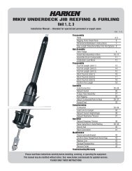
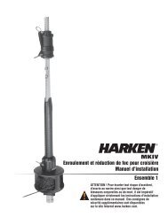
<strong>ESP</strong> JIB REEFING & FURLING<br />
Unit 2, 3<br />
Installation Manual – Intended for specialized personnel or expert users<br />
5003 10/13<br />
Preassembly<br />
Safety Precautions/Parts Descriptions 2 – 3<br />
Specifications 3<br />
Parts List 4 – 6<br />
Tools 6<br />
Top Foil 7 - 8<br />
Toggle Deductions/Stay Into Foil 9<br />
Confirm Foil Length 10<br />
Cutting/Drilling Top Foil 11 - 12<br />
Assembly<br />
Foils/Connectors/Halyard Deflector 13 – 17<br />
Halyard Swivel 17<br />
Drum Assembly 17 – 18<br />
Leg Kit with Toggle Assembly 19 – 21<br />
Final 22<br />
Commissioning<br />
Line to Cockpit/Line on Drum Assembly 23 – 24<br />
Storm Sails 24<br />
Raise Sail 25<br />
Check Halyards 26<br />
Operation<br />
Check Halyards 27<br />
Furl/Reef 28 – 29<br />
Secure Sail 29<br />
Adjust Turnbuckle 30<br />
Maintenance<br />
Clean/Inspect 31<br />
Storage 31<br />
Troubleshoot 32<br />
Product Registration 32<br />
Online Warranty/Product Registration 32<br />
Appendix<br />
Dimensions/Sailmaker's Instructions 33<br />
Please read these instructions carefully before installing, servicing, or operating the equipment.<br />
This manual may be modified without notice. See: www.harken.com/manuals for updated versions.<br />
PLEASE SAVE THESE INSTRUCTIONS
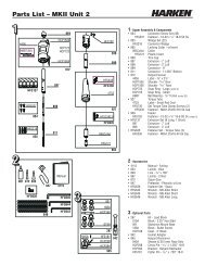
Parts Description<br />
Introduction<br />
This manual gives technical information on installation and service. This information is destined exclusively for<br />
specialized personnel or expert users. Installation, disassembling, and reassembling by personnel who are not<br />
experts may cause serious damage to property or injury to users and those in the vicinity of the product. If you<br />
do not understand an instruction contact <strong>Harken</strong>.<br />
The user must have appropriate training in order to use this product.<br />
<strong>Harken</strong> accepts no responsibility for damage or harm caused by not observing the safety requirements and<br />
instructions in this manual. See limited warranty, general warnings, and instructions in www.harken.com/manuals.<br />
Purpose<br />
<strong>Harken</strong> ® <strong>Jib</strong> Reefing and Furling is designed for rolling sails on sailboats to reduce sail size or to completely roll<br />
so wind has little effect on the sail. Use of this product for other than normal sailboat applications is not covered<br />
by the limited warranty.<br />
Safety Precautions<br />
WARNING! This symbol alerts you to potential hazards that may kill or hurt you and others<br />
if you don't follow instructions. The message will tell you how to reduce the<br />
chance of injury.<br />
CAUTION! This symbol alerts you to potential hazards that may hurt you and others if<br />
you do not follow instructions. The message will tell you how to reduce the<br />
chance of injury.<br />
8<br />
WARNING! Strictly follow all instructions to avoid potential<br />
hazards that may kill or hurt you and others. See www.harken.com/<br />
manuals, for general warnings and instructions.<br />
11<br />
12<br />
9<br />
10<br />
8<br />
7<br />
3 4<br />
6<br />
3a<br />
1<br />
2<br />
3c<br />
5<br />
3b<br />
Parts Descriptions<br />
1. Leg Kit with Toggle<br />
2. Leg Kit Collar<br />
3. Drum Assembly<br />
a. Neck<br />
b. Guard Posts<br />
c. Spool<br />
4. Adjuster Tube Clamp Screws<br />
5. Bow Shackle<br />
6. Adjuster Tube Bushing<br />
7. Adjuster Tube<br />
8. Foil Screws<br />
9. Connector Bushings<br />
10. Feeder<br />
11. Foil (2 m)<br />
12. Connector<br />
13. Top Foil<br />
a. Trim Cap Holes<br />
14. Halyard Swivel<br />
15. Trim Cap Screws<br />
16. Trim Cap<br />
2 <strong>ESP</strong> Unit 2, 3
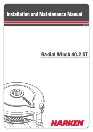
Preassembly<br />
Specifications<br />
15<br />
Online Product Registration<br />
www.harken.com/FurlingWarranty<br />
14<br />
16<br />
5<br />
13<br />
13a<br />
9<br />
8<br />
12<br />
11<br />
Unit 2<br />
15 1 /2"<br />
(260 mm)<br />
Unit 3<br />
18 7 /8"<br />
(260 mm)<br />
1) Leg Kit with Toggle Assembly<br />
Medium Leg Kit<br />
Unit 2 – 7322.22<br />
Unit 3 – 7323.22<br />
Max Turnbuckle Length<br />
a<br />
d<br />
e<br />
c<br />
f<br />
b<br />
g h<br />
i<br />
j<br />
k<br />
h<br />
l<br />
g<br />
c<br />
f<br />
e<br />
b<br />
d<br />
a<br />
a. Leg Kit Collar Screw<br />
b. Collar<br />
c. Short, Medium or Long Leg<br />
d. Lock Nut<br />
e. Washers<br />
f. Flat Hole in Plate<br />
g. Cotter Pin<br />
h. Spacer<br />
i. Threaded Cross Pin<br />
j. Clevis Pin<br />
k. Jaw/Jaw Toggle<br />
l. Cotter Pin<br />
Unit 2, 3 Short, Medium, and Long<br />
Unit Part Numbers<br />
Unit<br />
Unit without Leg Kit with Toggle Leg Kit with Toggle Leg Kit with Toggle Clevis Pin<br />
Lower Toggle Assembly – Short Assembly – Medium Assembly – Long<br />
Ø<br />
2 7322.10 7322.20 7322.22 7322.21<br />
5 /8", 3 /4"<br />
(15.9, 19.1 mm)<br />
3 7323.10 7323.20 7323.22 7323.21<br />
7 /8", 1"<br />
(22.2, 25.4 mm)<br />
Note: When using a turnbuckle you must use a Medium or Long Leg Kit assembly. *Check max turnbuckle length above.<br />
Wire<br />
Ø<br />
5 /16", 3 /8", 7 /16"<br />
(8, 10, 12 mm)<br />
1 /2", 9 /16", 5 /8"<br />
(12.7, 14, 16 mm)<br />
Rod<br />
Sizes<br />
-12 -17, -22<br />
(7.14, 8.38, 9.53 mm)<br />
-22, -30, -40<br />
(9.53, 11.10, 12.7 mm)<br />
<strong>ESP</strong> Unit 2, 3 3
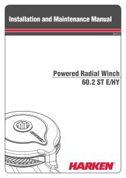
Parts List<br />
Drum Box<br />
Leg Kit Relative Sizes<br />
L<br />
Halyard Swivel<br />
Short Medium Long<br />
Short Leg Kit<br />
DO NOT USE with turnbuckle<br />
Adjuster Tube<br />
Clamp Screws<br />
L<br />
Drum Assembly<br />
Medium or Long Leg Kit<br />
Required for installation with turnbuckle<br />
Bow Shackles<br />
Blue Loctite ®<br />
Drum Box<br />
Description<br />
Unit 2 Unit 3<br />
Part No. Size Length* (L) Qty Part No. Size Length* (L) Qty<br />
Halyard swivel H-56229 — — 1 H-57148 — — 1<br />
Drum assembly 7322.10BASE — — 1 7323.10BASE — — 1<br />
Bow shackles 2117 8 mm — 3 2124 10 mm — 3<br />
Short leg kit with toggle 7322.20 5 /8", 3 /4" 3 1 /4" (264 mm) 1 7323.20 7 /8", 1" 4" (99 mm) 1<br />
Medium leg kit with toggle 7322.22 5 /8", 3 /4" 10 1 /2" (264 mm) 1 7323.22 7 /8", 1" 12 1 /2" (320 mm) 1<br />
Long leg kit with toggle 7322.21 5 /8", 3 /4" 15" (378 mm) 1 7323.21 7 /8", 1" 18 1 /4" (466 mm) 1<br />
Adjuster tube clamp screws HFS1252 8 mm — 4 HFS1252 8 mm — 5<br />
Blue Loctite ® 833 — — 1 833 — — 1<br />
* Lengths are approximate to distinguish between Short, Medium and Long.<br />
4 <strong>ESP</strong> Unit 2, 3
Parts List<br />
Foil Set<br />
Trim Cap<br />
Trim Cap<br />
Screws<br />
Adjuster<br />
Tube<br />
2 meter Foils<br />
Top Foil<br />
Foil Screws<br />
Connectors<br />
Feeder<br />
Red Loctite ®<br />
Connector Bushings<br />
Foil Set<br />
Description<br />
Unit 2 Unit 3<br />
Part Qty Part Qty<br />
Included<br />
Trim cap H-55977 2 H-57123 2<br />
Trim cap screws HFS1127 2 HFS1127 2<br />
Adjuster tube 7322.33 1 7323.33 1<br />
Foils (2 m) 7322.30 7 7323.30 9<br />
Top foil 7322.34 2000 1 7323.34 2000 1<br />
Foil screws HFS385 39 HFS383 47<br />
Connectors H-55900 7 H-57072 9<br />
Connector bushings H-55901 16 H-57122 20<br />
Feeder H-55905 1 H-57110 1<br />
Adjuster Tube Bushing MP-1977 2 MP-1978 2<br />
Red Loctite ® HFG739 2 HFG739 2<br />
Order Separately<br />
Extra Foil (see pages 7 - 8) 7322.30 1 7323.30 1<br />
Extra Connector with bushings 7322.31 1 7323.31 1<br />
Adjuster Tube Bushing<br />
<strong>ESP</strong> Unit 2, 3 5
Parts List<br />
Parts Sold Separately/Tools<br />
Required parts sold separately by <strong>Harken</strong>:<br />
WARNING! Wire that is old<br />
• Extra foil and connector if required. See pages 7 - 8.<br />
or damaged may break suddenly,<br />
causing an accident.<br />
• <strong>Harken</strong> Short Leg Kit with toggle. Do not use with turnbuckle.<br />
• <strong>Harken</strong> Medium or Long Leg Kit with toggle. Required for turnbuckle.<br />
Headstay condition should<br />
• Rod rigging requires <strong>Harken</strong> rod adapter stud.<br />
be checked by a professional<br />
rigger before reusing.<br />
• Furling line except Unit 3. To purchase elsewhere, figure length required:<br />
Boat length + foot length of largest sail + 6' (1.8 m).<br />
Optional parts, sold separately by <strong>Harken</strong>:<br />
• Halyard Deflector. Use when halyard exits very close to stay attachment point.<br />
• 7404 Lead Block Kit and one additional 7403 if necessary. Fits 1" (25 mm) stanchions.<br />
Required Parts<br />
Optional Parts<br />
7404 Lead Block Kit<br />
Includes 3 x 7403; 1 x 7401;<br />
1 x 7402; 1 Horn Cleat<br />
Short Leg Kit with Toggle Medium Leg Kit with Toggle Long Leg Kit with Toggle<br />
Do not use with turnbuckle Required for turnbuckle Required for turnbuckle<br />
Clevis Pin<br />
Clevis<br />
Clevis<br />
Unit Part No.<br />
Part No. Pin Part No. Pin<br />
2 7322.20 5 /8, 3 /4 7322.22 5 /8, 3 /4 7322.21 5 /8, 3 /4<br />
3 7323.20 7 /8, 1 7323.22 7 /8, 1 7323.21 7 /8, 1<br />
Rod Rigging: <strong>Harken</strong> Rod Adapter Stud Required<br />
Rod Size<br />
Thread<br />
Size UNF<br />
Part<br />
No.<br />
-12 7.14 mm 5 /8" 7421 -6<br />
-17 8.38 mm 5 /8" 7425 -17<br />
-22 9.53 mm 3 /4" 7426 -22<br />
-30 11.10 mm 7 /8" 7427 -30<br />
Halyard Deflector<br />
Unit Part No.<br />
2 7303<br />
3 7304<br />
Furling Line<br />
Unit Part No. Line Ø Length (ft)<br />
2 HFG235 8 mm 100<br />
3 * 12 mm See Above<br />
*Not available from <strong>Harken</strong><br />
Preassembly<br />
Tools Required<br />
1. Hex keys<br />
Unit<br />
Size<br />
1<br />
2 6 mm<br />
3 6 mm, 8 mm<br />
2<br />
2. Socket or open end wrench<br />
3<br />
Unit<br />
Size<br />
2 18 mm<br />
3 18 mm<br />
3. Long tape measure 11. Phillips screwdriver<br />
4. Short tape measure 12. Slotted screwdriver<br />
5. Drill bit – 1/8" (3 mm) 13. Needle-nose pliers<br />
6. Power drill 14. Locking Pliers<br />
7. Hacksaw 15. Center punch<br />
8. Side cutters 16. Hammer<br />
9. Rat-tail file 17. Electric Tape (Use to Mark Foil)<br />
10. Straight edge 18. Vise ( Tape Jaws to Protect Foil)<br />
10<br />
8<br />
4<br />
9<br />
5<br />
11<br />
17<br />
6<br />
12<br />
12<br />
14<br />
13<br />
18<br />
15<br />
7<br />
16<br />
6 <strong>ESP</strong> Unit 2, 3
Preassembly<br />
Measure A and add to this chart<br />
and length chart below<br />
Inches mm<br />
A<br />
B 1.3* 33*<br />
E 22.5 570<br />
F 6.3 160<br />
G<br />
Total A+B+E+F+G<br />
*Add 1.4" (35 mm) if using a halyard deflector.<br />
UNIT 2<br />
Tip: Check to see if the foil fits over<br />
the marine eye. If yes, assemble foils<br />
and lower <strong>unit</strong> following instructions.<br />
Measure and cut the top foil after<br />
other foils are assembled.<br />
IMPORTANT! Identify top foil before<br />
cutting. Use end with foil screw<br />
holes for connector.<br />
Make sure upper<br />
measurement points<br />
of A and pin-to-pin<br />
are the same.<br />
Alternate<br />
Measurement<br />
Point<br />
TOP FOIL LENGTH WORKSHEET<br />
1 Pin-to-Pin Length<br />
2 Subtract ABEFG –<br />
3 Result (Pin-to-Pin – ABEFG)<br />
4 Subtract D –<br />
To find “D” pick number from chart below that is closest to,<br />
but not greater than total from step 3.<br />
Inches<br />
mm<br />
5 x 78.74 = 393.7<br />
6 x 78.74 = 472.4<br />
7 x 78.74 = 551.2<br />
8 x 78.74 = 629.9<br />
9 x 78.74 = 708.7<br />
5 x 2000 = 10000<br />
6 x 2000 = 12000<br />
7 x 2000 = 14000<br />
8 x 2000 = 16000<br />
9 x 2000 = 18000<br />
Example–If result from Step 3 is:<br />
500 inches “D” = 472.4 inches 12,500 mm “D” = 12,000 mm<br />
5 Result (C) Top Foil Length<br />
A<br />
Pin<br />
to<br />
Pin<br />
Top Foil Length<br />
A<br />
B<br />
C<br />
D<br />
Length Check<br />
After completing worksheet above fill in A, C, D and G below. Add “A” through<br />
“G” to confirm total equals your pin-to-pin measurement.<br />
Length Chart<br />
Dimensions Inches mm<br />
A Center of Pin to Bottom of Terminal<br />
B Bottom of Terminal to Top of Foil 1.3* 33*<br />
C Top Foil Length ** **<br />
D Number of Foils ________ x 78.74" (2000 mm)<br />
E Adjuster Tube at Just Over Midpoint 22.5 570<br />
F Drum Height 6.3 160<br />
G Top of Leg Kit to Clevis Pin<br />
Pin-to-Pin Length<br />
*Add 1.14" (35 mm) if using a halyard deflector.<br />
**If top foil length is 9" to 6" (230 to 150 mm) cut the foil at 9" (230 mm). If the top foil<br />
is shorter than 6" (150 mm) do not use a cut top foil. A full length foil will be the top foil.<br />
G Top of Leg Kit to Clevis Pin<br />
Toggle<br />
Clevis Pin<br />
G Distance<br />
Part No.<br />
Type<br />
in mm in mm<br />
7322.20 5/8 Short Leg Kit 5/8" 15.9 mm 4.9 125<br />
7322.20 3/4 Short Leg Kit 3/4" 19.1 mm 4.9 125<br />
7322.22 5/8 Medium Leg Kit 5/8" 15.9 mm 11.9 302<br />
7322.22 3/4 Medium Leg Kit 3/4" 19.1 mm 12.2 310<br />
7322.21 5/8 Long Leg Kit 5/8" 15.9 mm 16.7 425<br />
7322.21 3/4 Long Leg Kit 3/4" 19.1 mm 16.7 425<br />
E<br />
F<br />
G<br />
Pin<br />
to<br />
Pin<br />
<strong>ESP</strong> Unit 2 7
Preassembly<br />
Measure A and add to this chart<br />
and length chart below<br />
Inches mm<br />
A<br />
B 2.0* 51*<br />
E 22.9 580<br />
F 7.4 188<br />
G<br />
Total A+B+E+F+G<br />
*Add 1.5" (38 mm) if using a halyard deflector.<br />
UNIT 3<br />
Tip: Check to see if the foil fits over<br />
the marine eye. If yes, assemble foils<br />
and lower <strong>unit</strong> following instructions.<br />
Measure and cut the top foil after<br />
other foils are assembled.<br />
IMPORTANT! Identify top foil before<br />
cutting. Use end with foil screw<br />
holes for connector.<br />
Make sure upper<br />
measurement points<br />
of A and pin-to-pin<br />
are the same.<br />
Alternate<br />
Measurement<br />
Point<br />
TOP FOIL LENGTH WORKSHEET<br />
1 Pin-to-Pin Length<br />
2 Subtract ABEFG –<br />
3 Result (Pin-to-Pin – ABEFG)<br />
4 Subtract D –<br />
To find “D” pick number from chart below that is closest to,<br />
but not greater than total from step 3.<br />
Inches<br />
mm<br />
7 x 78.74 = 551.2<br />
8 x 78.74 = 629.9<br />
9 x 78.74 = 708.7<br />
10 x 78.74 = 787.4<br />
11 x 78.74 = 866.1<br />
7 x 2000 = 14000<br />
8 x 2000 = 16000<br />
9 x 2000 = 18000<br />
10 x 2000 = 20000<br />
11 x 2000 = 22000<br />
Example–If result from Step 3 is:<br />
800 inches “D” = 787.4 inches 20,500 mm “D” = 20000 mm<br />
5 Result (C) Top Foil Length<br />
A<br />
Pin<br />
to<br />
Pin<br />
Top Foil Length<br />
A<br />
B<br />
C<br />
D<br />
Length Check<br />
After completing worksheet above fill in A, C, D, and G below. Add “A” through<br />
“G” to confirm total equals your pin-to-pin measurement.<br />
Length Chart<br />
Dimensions Inches mm<br />
A Center of Pin to Bottom of Terminal<br />
B Bottom of Terminal to Top of Foil 2.0* 51*<br />
C Top Foil Length<br />
D Number of Foils ________ x 78.84" (2000 mm)<br />
E Adjuster Tube at Just Over Midpoint 22.9 580<br />
F Drum Height 7.4 188<br />
G Top of Leg Kit to Clevis Pin<br />
Pin-to-Pin Length<br />
*Add 1.5" (38 mm) if using a halyard deflector.<br />
**If top foil length is 11" to 7" (275 to 175 mm) cut the foil at 11" (275 mm). If the top foil<br />
is shorter than 7" (175 mm) do not use a cut top foil. A full length foil will be the top foil.<br />
G Top of Leg Kit to Clevis Pin<br />
Toggle<br />
Clevis Pin<br />
G Distance<br />
Part No.<br />
Type<br />
in mm in mm<br />
7323.20 7/8 Short Leg Kit 7/8" 22.2 mm 6.5 165<br />
7323.20 1 Short Leg Kit 1" 25.4 mm 6.5 165<br />
7323.22 7/8 Medium Leg Kit 7/8" 22.2 mm 15.0 380<br />
7323.22 1 Medium Leg Kit 1" 25.4 mm 15.4 391<br />
7323.21 7/8 Long Leg Kit 7/8" 22.2 mm 21.1 535<br />
7323.21 1 Long Leg Kit 1" 25.4 mm 21.1 535<br />
8 <strong>ESP</strong> Unit 3<br />
E<br />
F<br />
G<br />
Pin<br />
to<br />
Pin
Preassembly<br />
Toggle Deductions/Stay Into Foil Options<br />
Rigger supplied: Eye at lower end of stay or turnbuckle to mate with toggle. Use dimensions of <strong>Harken</strong> toggle<br />
below to build stay to correct length.<br />
Tip: Turnbuckles should be one-half to two-thirds open to allow shortening for new wire stretch and for fine-tuning<br />
mast rake.<br />
Pin-to-Pin Length<br />
Short Leg Kit<br />
with Toggle<br />
Leg Kit Toggle<br />
Assembly<br />
Clevis Pin<br />
Ø<br />
Pin-to-Pin (P-P)<br />
Length<br />
Unit Type Part No. in mm in mm<br />
Short 7322.20 5/8<br />
Medium 7322.22 5/8 5 /8 16 2 1 /16 52<br />
2<br />
Long 7322.21 5/8<br />
Short 7322.20 3/4<br />
Medium 7322.22 3/4 3 /4 19 2 3 /8 60<br />
Long 7322.21 3/4<br />
Short 7323.20 7/8<br />
Medium 7323.22 7/8 7 /8 22 3 76<br />
3<br />
Long 7323.21 7/8<br />
Short 7323.20 1<br />
Medium 7323.22 1 1 25 3 7 /16 87<br />
Long 7323.21 1<br />
Pin-to-Pin<br />
Length<br />
Turnbuckle<br />
with Marine Eye<br />
Medium or Long Leg Kit<br />
with Toggle<br />
Options for Snaking Stay into Foils<br />
1. Swage Stud<br />
3. Wire for Mechanical Terminal<br />
2. Marine Eye<br />
4. <strong>Harken</strong> Rod Adapter Nosepiece<br />
WARNING! Using a threaded nosepiece with only adhesive at the upper rod eye terminal may result in headstay<br />
system failure. Use a <strong>Harken</strong> rod adapter stud. See www.harken.com/manuals for additional safety<br />
information.<br />
<strong>ESP</strong> Unit 2, 3 9
Preassembly<br />
Confirm Foil Length<br />
Confirm foil length by laying foils alongside stay with turnbuckle components. Pull stay straight. Attach <strong>Harken</strong><br />
toggle to bottom of stay. Adjust turnbuckle, if used, so that length of stay with <strong>Harken</strong> toggle will fit boat. Ideally,<br />
turnbuckle will be one-half to two-thirds open to allow for rig adjustment. Temporarily clamp short or long leg kit<br />
to bottom of <strong>unit</strong>. Line up:<br />
A. Bottom of full length foil with holes in adjuster tube. Set adjuster tube just above the mid-point of adjustment<br />
range.<br />
B. Holes at lower end of adjust tube with drum assembly holes.<br />
C. Lower holes in leg kit line up with eye in toggle.<br />
Full-Length Foil<br />
A<br />
Feeder<br />
B<br />
C<br />
Adjuster Tube<br />
Actual adjuster tube will have 12 to 14 adjuster holes. Line up the foil so it is just above the midpoint of adjustment.<br />
Lay all foils out alongside stay and confirm that there will be enough space between the bottom of the marine<br />
eye and the end of the top foil. If necessary, go to lower end, reposition the adjuster tube and lower full length<br />
foil to another position. Confirm that there are two holes for the foil and one for the feeder.<br />
Deflector<br />
No Deflector<br />
Unit in mm In mm<br />
2 2 1 /2 65 1 1 /4 30<br />
3 3 1 /2 90 2 50<br />
Tip: Check to see if the foil fits over the marine eye. If yes, assemble all foils and lower <strong>unit</strong> following<br />
instructions. Measure and cut the top foil when all other foils are assembled.<br />
10 <strong>ESP</strong> Unit 2, 3
Assembly<br />
Cutting/Drilling Top Foil<br />
Determine top foil length using charts or by laying foils alongside wire. IMPORTANT! Confirm that you are using the<br />
correct <strong>unit</strong> size worksheet. Be sure to lay foils, lower <strong>unit</strong>, and leg kit alongside stay to confirm length before cutting.<br />
Use tape to mark foil. Cut foil to length.<br />
Tool: hacksaw<br />
Trim Cap Holes<br />
Cut off this end with trim cap hole. Hole is<br />
only used with full length 78 3 /4" (2000 mm)<br />
foil as top foil.<br />
Foil screw holes<br />
for connector<br />
Deburr inside edge using a file.<br />
Tool: rat-tail file<br />
Label top foil and identify which end will be<br />
at the top when installed. You will be drilling<br />
each side near the top.<br />
Lay top foil alongside cutoff piece. Use<br />
locking pliers to clamp foils together at the<br />
interior flat surfaces opposite the<br />
sail grooves.<br />
Use a flat metal object (i.e. metal ruler) to<br />
scribe lines on one side of foil. Leave foils<br />
clamped for drilling.<br />
Top Foil<br />
Tools: straight edge, locking pliers<br />
<strong>ESP</strong> Unit 2, 3 11
Assembly<br />
Cutting/Drilling Top Foil<br />
Measure from the end of the foil and put a<br />
mark showing hole distance from top of foil.<br />
Unit<br />
Decimal<br />
in<br />
Fraction<br />
in mm<br />
2 1.38" 1 3 /8" 35<br />
3 1.77" 1 3 /4" 45<br />
Top Foil<br />
Tool: short tape measure<br />
Use center punch to start hole. Drill one of<br />
two holes for trim cap.<br />
Drill Size: 1 /8" (3.2 mm)<br />
Keeping foils clamped together, flip them to<br />
the other side and repeat the procedure so<br />
there is a hole on each side.<br />
Top Foil<br />
Tools: electric drill, drill bit, center<br />
punch<br />
12 <strong>ESP</strong> Unit 2, 3
Assembly<br />
Cutting/Drilling Top Foil<br />
1. Identify special length top foil with trim<br />
cap holes.<br />
Trim Cap Holes<br />
2. Slide top foil and 2 m foils and<br />
connectors onto wire.<br />
2a. Load connector so cutouts for<br />
bushings are facing up towards<br />
the top of stay.<br />
Note: On top foils under 12" (300 mm),<br />
load upper connector so that the cutouts<br />
for bushings face down towards the<br />
bottom of the stay.<br />
2b. Load onto wire from top and/or<br />
bottom.<br />
a. Cutouts<br />
b. Top of Stay<br />
3. Make sure that special length top foil<br />
with trim cap holes is at top of stay.<br />
Trim cap holes<br />
<strong>ESP</strong> Unit 2, 3 13
Assembly<br />
Foils/Connectors/Halyard Deflector<br />
4. Put trim cap halves together over wire<br />
and tap in place.<br />
Tool: hammer<br />
5. Secure with trim cap screws.<br />
Tool: Phillips screwdriver<br />
6. If using halyard deflector, install above<br />
foil. Use red Loctite ® on screws.<br />
Halyard Deflector<br />
Red Loctite ®<br />
14 <strong>ESP</strong> Unit 2, 3
Assembly<br />
Foils/Connectors<br />
7. Hold plastic bushing halves in cutouts<br />
and over wire and insert up into foil.<br />
7a. Make sure foil and connector<br />
screw holes are facing up.<br />
7b. Make sure connector and foil<br />
are aligned.<br />
a.<br />
b.<br />
8. Put red Loctite ® in foil screw holes and<br />
secure with foil screws.<br />
Tool: slotted screwdriver<br />
<strong>ESP</strong> Unit 2, 3 15
Assembly<br />
Foils/Connectors<br />
9. Join lower part of connector to next foil.<br />
Put red Loctite ® on screw holes. Secure<br />
with foil screws.<br />
10. Install connector bushings in top of<br />
adjuster tube and insert into 2 m foil.<br />
Adjuster Tube<br />
10a. Make sure foil and adjuster tube<br />
screw holes are facing up.<br />
10b. Make sure adjustor tube and foil<br />
are aligned.<br />
10c. Do not fasten with foil screws at<br />
this time.<br />
a.<br />
b.<br />
16 <strong>ESP</strong> Unit 2, 3
Assembly<br />
Foils/Connectors/Halyard Swivel/Feeder/Drum Assembly<br />
11. Place adjuster tube bushings over wire<br />
and insert into foils until tab snaps into<br />
holes on either side of adjuster tube.<br />
Tap in place.<br />
Tool: hammer<br />
12. Slide halyard swivel onto foil so longer<br />
part is toward top of stay.<br />
Top<br />
13. Slide feeder onto adjuster tube. Do<br />
not secure with screw until later.<br />
<strong>ESP</strong> Unit 2, 3 17
Assembly<br />
Drum Assembly<br />
14. Slide drum assembly onto adjuster tube.<br />
15. Put blue Loctite ® on screw holes.<br />
Secure with adjuster tube clamp<br />
screws.<br />
16. Capture jaw/jaw toggle on eye using<br />
threaded crosspin.<br />
When using <strong>Harken</strong> rod<br />
adapter stud, be sure to use<br />
red Loctite ® and cotter pins<br />
to lock nosepiece into stud.<br />
18 <strong>ESP</strong> Unit 2, 3
Assembly<br />
Leg Kit with Toggle Assembly<br />
17. Slide one spacer on either<br />
side of jaw/jaw toggle.<br />
18. Secure using cotter pins. Tools: slotted screwdriver, side cutters<br />
19. Slip leg and washers onto<br />
threaded crosspin.<br />
<strong>ESP</strong> Unit 2, 3 19
Assembly<br />
Leg Kit with Toggle Assembly<br />
19a. Make sure flat holes in leg line up with threaded crosspin flats.<br />
Line up flats<br />
19b. Secure using washers and locknuts.<br />
Tools: Socket or Open End Wrench<br />
Unit<br />
Size<br />
2 16 mm<br />
3 18 mm<br />
If stay length is set, use side cutters<br />
or needlenose pliers to bend cotter<br />
pin to secure turnbuckle.<br />
20. Capture legs in one of the two collars.<br />
Tip: If the legs do not fit collar, loosen<br />
Locknuts at threaded crosspin.<br />
Collar<br />
20 <strong>ESP</strong> Unit 2, 3
Assembly<br />
Leg Kit with Toggle Assembly<br />
21. Slip Leg Kit assembly onto neck of<br />
drum assembly and fit other collar.<br />
22. Secure using Collar Screws.<br />
Tools: Hex Key<br />
Unit<br />
Size<br />
2 6 mm<br />
3 8 mm<br />
23. Push the assembled foils up toward the<br />
top of the stay leaving 1" to 2" (25 to<br />
50 mm) of space between the top of<br />
the deflector or the trim cap and bottom<br />
of marine eye. Align all three holes at<br />
bottom of adjuster tube. Check to make<br />
sure there is space above halyard<br />
deflector or trim cap.<br />
Unit<br />
Approximate Space<br />
mm in<br />
2 30 1 1 /4<br />
3 50 2<br />
<strong>ESP</strong> Unit 2, 3 21
Assembly<br />
Final<br />
24. Locate nearest group of three screw<br />
holes in adjuster tube, two for the<br />
foil and one for the feeder. Put blue<br />
Loctite ® in screw holes. Secure adjuster<br />
tube with foil screws.<br />
Tool: slotted screwdriver<br />
Blue Loctite ®<br />
25. Slide feeder to third hole and secure<br />
using foil screw and blue Loctite ® .<br />
Tool: slotted screwdriver<br />
26. Once on boat, loosen collar screws<br />
enough to rotate opening in drum<br />
assembly towards lead blocks. Put<br />
blue Loctite ® on screws and tighten.<br />
Tools: Hex Driver<br />
Unit<br />
Size<br />
2 6 mm<br />
3 8 mm<br />
22 <strong>ESP</strong> Unit 2, 3
Assembly<br />
Line to Cockpit<br />
Mount Lead Blocks<br />
Note: <strong>Harken</strong> lead blocks referenced below are an available option. Boat manufacturers may have alternate<br />
methods of running furling line to cockpit.<br />
Furling line can be led down either side of boat. If boat is in slip, consider mounting opposite dock.<br />
Remove four screws on stanchion blocks. Clamp blocks to stanchions. See instructions below.<br />
Tip: Start all four screws before tightening.<br />
BOW<br />
7401<br />
FORWARD<br />
STANCHION<br />
BLOCK<br />
7403<br />
OUTBOARD<br />
STANCHION<br />
BLOCK<br />
7401 Forward Stanchion Block<br />
Position 7401 Forward Stanchion Block so line enters<br />
drum at right angles to headstay and centers vertically<br />
in opening. Install so line is inside stanchion.<br />
Correct block position is critical to even line<br />
spooling and ease of furling.<br />
7403 Outboard Stanchion Blocks<br />
Install 7403 Outboard Stanchion Blocks so line is<br />
outside stanchions.<br />
Number and placement of leads depends on boat<br />
length and number/configuration of stanchions.<br />
7403<br />
OUTBOARD<br />
STANCHION<br />
BLOCK<br />
7403<br />
OUTBOARD<br />
STANCHION<br />
BLOCK<br />
7402 Ratchet Stanchion Block<br />
Mount 7402 Ratchet Stanchion Block as farthest-aft<br />
lead to prevent line overrides in drum when unfurling.<br />
Position ratchet block so line turns at least 90°.<br />
Install so line is inside stanchion.<br />
Lead line through block so ratchet makes a clicking<br />
sound when pulling line to furl sail.<br />
Tip: Make sure ratchet switch is in “ON" position.<br />
If there is no clicking sound, lead line through<br />
block in opposite direction.<br />
Lead line to furling line cleat in cockpit.<br />
90°<br />
HCP168 Furling Line Cleat<br />
STERN<br />
7402<br />
RATCHET<br />
STANCHION<br />
BLOCK<br />
Install so line is angled as shown. Use #10 (5 mm)<br />
fasteners.<br />
Note: As furling line lead changes, make sure line<br />
doesn't chafe against line guard. Rotate drum<br />
assembly if necessary, see page 22.<br />
Spool Full<br />
(sail unfurled)<br />
Spool Empty<br />
(sail furled)<br />
<strong>ESP</strong> Unit 2, 3 23
Commissioning<br />
Line on Drum Assembly/Storm Sails<br />
Add Line to Drum Assembly<br />
Run line into drum assembly between guard posts and out hole in lower plate of spool. Exit opening in drum<br />
assembly as shown below. Tie a small overhand knot and pull it up tightly against spool.<br />
IMPORTANT! Do not run line through plastic opening in drum assembly.<br />
Guard<br />
Posts<br />
Do not run line through this opening.<br />
Wrap Line on Spool<br />
Note location of sun cover on sail. Rotate spool to wrap line.<br />
Line through hole and opening.<br />
Tie a small overhand<br />
knot and pull it up tightly<br />
against spool. Spool<br />
must turn freely to furl<br />
and unfurl sail easily.<br />
Sun Cover On<br />
Starboard<br />
Port<br />
Turn Spool<br />
Clockwise<br />
Counterclockwise<br />
Turn spool until there is a tail of line in the cockpit measuring about 1.5 m (5') beyond the cleat or rope clutch.<br />
Sun cover on starboard side: wrap line by<br />
turning clockwise<br />
Sun cover on port side: wrap line by turning<br />
counterclockwise<br />
Storm Sails<br />
Storm sails or heavy air working jibs are necessary when sailing offshore where it is not possible to easily<br />
reach safe harbor.<br />
These sails will generally require pendants to ensure that halyard swivel is properly positioned at top of<br />
headstay. See page 26.<br />
Remember that heavy air working jibs and storm jibs may be reefed and furled like any other sail.<br />
24 <strong>ESP</strong> Unit 2, 3
Commissioning<br />
Raise Sail<br />
WARNING! Sail can become uncontrollable when raising in windy conditions, resulting in loss of footing.<br />
Choose wind conditions to match your experience and ability. If changing sails underway, take all safety<br />
precautions when working on the foredeck. See www.harken.com/manuals General Warnings and<br />
Instructions.<br />
Raise Sail<br />
Choose conditions with little or no wind when raising sail at the dock.<br />
Have bow of boat pointing into the wind.<br />
1) Note: Make sure drum assembly is wrapped with line. Shackle<br />
tack of sail to drum. Install shackle so screw pin head is on same<br />
side as sun cover.<br />
2) Secure genoa sheets to clew of sail using bowline knot.<br />
See www.harken.com/knots or consult a knot-tying book.<br />
IMPORTANT! If you are not comfortable tying this or other<br />
secure knots, get help from professional rigger.<br />
3) Attach genoa halyard to halyard swivel.<br />
4) Carefully guide sail into feeder and then into foil groove.<br />
5) Attach head or pendant at head of sail to halyard swivel.<br />
6) Hoist sail slowly, making sure luff tape does not jam in foil.<br />
Important! Forcing sail can cause luff tape to rip.<br />
Tip: New sails are often stiff and may hang up at feeder during<br />
raising. Do not force sail when it hangs up—lower and remove<br />
twist. Sails "break in" with use and will become easier to raise.<br />
7) Line up front of sail so it is parallel to foil and feeds smoothly when<br />
sail is hoisted.<br />
8) Put moderate tension on the halyard and secure.<br />
9) Check the top area of the furler for interference from halyards.<br />
See “Check Halyards."<br />
10) Practice rolling sail in and out at the dock. See “Furl" and “Unroll Sail."<br />
11) If not sailing right away, make sure sail is furled carefully.<br />
See “Secure Sail."<br />
IMPORTANT! Pay careful attention to “Secure Sail.” If leaving the<br />
boat, you must secure sail to prevent damage if wind increases while<br />
you are away.<br />
Feeder<br />
Tack<br />
Head<br />
<strong>ESP</strong> Unit 2, 3 25
Commissioning<br />
Check Halyards<br />
Once sail is raised, stand back from boat and use binoculars to make sure<br />
there is no interference from halyards.<br />
The jib halyard must exert a slight pull to the rear. This allows the foil to<br />
turn while halyard remains stationary.<br />
1. Halyard swivel must be 40 mm (1 1 /2")–150 mm (6") from top of foil.<br />
2. Halyard must pull slightly to rear (8°–10°).<br />
Halyard Deflector<br />
If the stay attachment is close to the halyard exit the halyard will not<br />
pull to the rear 8° or more and can catch on the top of the foil. Use<br />
halyard deflector to move the halyard away. Check to make sure there<br />
is enough space between the trim cap and the bottom of the terminal.<br />
Halyard deflector thickness:<br />
Short Luff Length Sail<br />
If sail luff is too short to position the halyard swivel 40 mm–100 mm<br />
from top of foil assembly, you must add a pendant to the head of sail.<br />
Determine Pendant Length<br />
1. Raise sail, but do not attach tack to drum assembly.<br />
2. Position halyard swivel 40–150 mm from top of foil.<br />
3. Secure halyard.<br />
4. Tie a piece of rope between sail tack and tack shackle.<br />
6. Tension sail.<br />
7. Measure distance from tack shackle to sail tack.<br />
Have a rigger make a pendant to this length using plasticcoated<br />
wire It should be permanently attached to head of sail.<br />
Check Halyards<br />
8–10°<br />
40–150 mm<br />
40–150 mm<br />
Pendant<br />
Head of Sail<br />
The most serious problem with furling systems occurs when the jib<br />
halyard wraps around the headstay foil. A halyard wrap will keep you<br />
from furling/unfurling and may cause serious damage to the <strong>unit</strong> and<br />
halyard.<br />
IMPORTANT! A furler with a low halyard swivel may furl correctly in<br />
smooth water/calm conditions, but the halyard will be likely to wrap in<br />
a rough sea.<br />
WARNING! In severe cases, a halyard wrap can cause loss<br />
of control of boat and/or headstay can break suddenly. Make<br />
sure halyard is clear of top foil before using system.<br />
If halyard wraps, do not force <strong>unit</strong> to turn. Attempt to open sail by<br />
carefully furling in and out a little at a time. If sail will unfurl, lower it<br />
by releasing jib halyard. If sail will not furl, try to remove one sheet<br />
and run the tied sheet around foil. Use sheet to pull sail around foil<br />
and repeat. This should only be attempted by expert users observing<br />
all safety requirements for going forward.<br />
26 <strong>ESP</strong> Unit 2, 3<br />
Halyard swivel<br />
is too low<br />
Halyard swivel<br />
is too low
Operation<br />
Halyard Tension<br />
The jib halyard should be firm, but not too tight.<br />
Tip: The foil supports sail along its length so halyard tension is used<br />
only to shape sails, not to support them. Use enough halyard tension to<br />
remove some wrinkles along luff of sail. Do not tension halyard enough<br />
to cause vertical wrinkles in luff of sail. Tension to adjust position of<br />
draft in sail to suit sailing conditions. Halyard should be firm but not<br />
tight. If in doubt ease halyard tension. To protect sail, ease halyard<br />
when boat is not in use.<br />
Check Halyards<br />
<strong>Jib</strong> Halyard<br />
Backstay Adjusters and Halyard Tension<br />
Backstay adjusters allow headstay tension to be varied to change sail shape to match<br />
conditions. They permit a very tight headstay to be eased when boat is not in use. For best<br />
performance, consider adding a backstay adjuster: either a block and tackle, a mechanical<br />
adjuster, or hydraulic adjuster like those offered by <strong>Harken</strong>.<br />
Remember to keep headstay tight for best performance when furling or reefing.<br />
IMPORTANT! Ease halyard before tensioning backstay adjuster. If not, backstay adjuster<br />
will increase halyard tension and could damage the sail or furling system.<br />
Racing boats often slack the headstay completely when sailing downwind. Check to be<br />
sure that foil does not jam against upper headstay terminal when backstay is released.<br />
It may be necessary to shorten foil slightly to prevent this.<br />
Spinnaker Halyards<br />
Make sure spinnaker halyards are clear of furler.<br />
WARNING! In severe cases, spinnaker<br />
halyards can jam furler causing loss of<br />
control of boat. Make sure all halyards<br />
are clear of top of top foil.<br />
On many boats it will not be possible to attach the<br />
spinnaker halyard to the bow pulpit or it may be<br />
"sucked" into jib when furling.<br />
On some boats the spinnaker halyard lays across the<br />
headstay and will catch on halyard swivel, foils, or<br />
jib halyard.<br />
Boats with external halyards may find it necessary to<br />
flip both ends of spinnaker halyard behind spreaders<br />
to prevent fouling with furling system.<br />
<strong>ESP</strong> Unit 2, 3 27
Operation<br />
Furl<br />
Unroll Sail<br />
Uncleat furling line. Pull sheets to unfurl sail.<br />
IMPORTANT! Keep tension on furling line when unrolling sail so line spools tightly on drum. Use a <strong>Harken</strong> ratchet block<br />
or keep tension on the line by putting a single wrap of the furling line around a spare winch to provide drag on the line. This<br />
is very important when wind is blowing over 10 knots. When line is tightly spooled on drum it furls in much easier.<br />
Furl<br />
To furl or reef, ease the jib sheets and pull furling line.<br />
In very light breeze, place some tension on jib sheet to insure a tight furl.<br />
In a stronger breeze, you must completely luff sail by totally slacking jib sheets before furling.<br />
The furling line should pull readily. The amount of force required is related to amount of wind, but a <strong>unit</strong> should never<br />
require use of a winch to furl. If the sail will not furl, or if furling requires a great deal of effort, there is a problem with<br />
system. Consult Troubleshoot on page 32. Do not use a winch to force a system to turn. If you are certain that system<br />
is operating properly you may use a winch to make furling easier.<br />
28 <strong>ESP</strong> Unit 2, 3
Operation<br />
Reef/Secure Sail<br />
Reef<br />
A sail may be partially furled before you resume sailing.<br />
This is known as reefing.<br />
Tip: Place marks on foot of sail for a variety of reefed jib<br />
sizes. Place marks on jib lead track so lead block position<br />
matches reefed jib.<br />
Reef sails to balance boat and reduce heel.<br />
Tip: Reef sails to improve visibility or to slow boat while<br />
sailing in congested areas, or while entering or leaving<br />
harbors.<br />
Secure Sail<br />
When furling the sail completely, make sure sheets and furling line are<br />
secured. Check amount of line on the spool compared to the furled sail<br />
before using the system.<br />
A furled sail must have:<br />
a. Two to three wraps of jib sheet wrapped around sail.<br />
b. Two wraps minimum of line wound on spool.<br />
c. Furling line securely cleated.<br />
d. <strong>Jib</strong>sheets securely wrapped on winch and held in self-tailing jaws.<br />
Furl at dock with tension on sheets to duplicate furling in high wind.<br />
Remember sails furled in light wind and left loosely secured can be a problem<br />
if wind increases.<br />
IMPORTANT! Remove sail from furler if extreme winds are predicted,<br />
especially if boat is left unattended.<br />
IMPORTANT! Check all points above—a, b, c, and d—when leaving boat<br />
to avoid damage to furler or boat. A loosely rolled sail can catch wind in<br />
a storm. Sheets or furling lines can loosen as winds increase and allow<br />
furler to unroll.<br />
Be sure mooring lines are not placed across furling line where they may<br />
cause chafe.<br />
IMPORTANT! If no wraps of line are on spool, the line deadend can break<br />
the spool when the boat motors through waves.<br />
a. 2–3 wraps<br />
b. 2–3 wraps<br />
If you want to:<br />
Add more wraps of<br />
jibsheet on furled sail.<br />
Add more wraps of line<br />
on spool.<br />
Untie jib sheets and keep sail<br />
completely rolled. Secure with<br />
sail tie.<br />
Turn spool to unroll a<br />
couple of wraps of line.<br />
Turn spool to add a<br />
couple of wraps of line.<br />
Retie sheets.<br />
<strong>ESP</strong> Unit 2, 3 29
Operation<br />
Adjust Turnbuckle<br />
Adjust Turnbuckle<br />
Tools: See page 6 for sizes<br />
Wrench for locknuts<br />
Hex Key<br />
Slotted screwdriver for foil screws<br />
Sidecutters for cotter pins<br />
Tip: Tape a flat cardboard box or a towel<br />
under the furler to catch any dropped<br />
parts.<br />
Attach halyard to tack shackle, take out<br />
slack and secure.<br />
Remove feeder screw and one foil screw.<br />
While holding foils up, carefully remove<br />
screw and lower foils to drum assembly.<br />
Tip: Have a helper lift foils and hold or<br />
use another halyard while removing last<br />
screw. To use a halyard to hold foils<br />
lifted, tie a rolling hitch to the foils using<br />
another line or use the actual halyard if<br />
suitable. See www.harken.com/knots<br />
for tying resources.<br />
CAUTION! Foils have considerable<br />
weight and can drop and cut hands<br />
if placed underneath. Make sure<br />
foils are securely held up while<br />
adjusting turnbuckle.<br />
Carefully remove plastic collar<br />
and screws.<br />
Do not drop.<br />
Loosen screws and separate legs<br />
from flats on crosspin. Rotate legs<br />
so they are laying on the deck.<br />
IMPORTANT! Parts are easily lost.<br />
Unlock turnbuckle and adjust.<br />
Lock turnbuckle and reassemble<br />
leg kit parts.<br />
Carefully loosen nut enough to move<br />
legs outwards and rotate out of the<br />
way. When reassembling, you must<br />
secure flats on both parts. See<br />
assembly step 19a, (page 20).<br />
30 <strong>ESP</strong> Unit 2, 3
Maintenance<br />
Clean/Inspect/Storage<br />
Clean<br />
Keep <strong>unit</strong> clean. When you wash boat, flush <strong>unit</strong> with soap and fresh water.<br />
Occasionally lower sail and flush halyard swivel with soap and fresh water.<br />
Clean <strong>unit</strong> more thoroughly at least twice a year. First remove line (note<br />
direction on spool) and flush bearings with soap and fresh water.<br />
Clean foils with soap and water. Run scrap of luff tape up foil groove to clean.<br />
WARNING! Parts can wear, loosen, or corrode and can break at<br />
load. Periodically inspect items listed below and any others as<br />
necessary. See www.harken.com/manuals General Warnings for<br />
additional safety information.<br />
Inspect<br />
1) Unit for signs of chafe, wear, or damage.<br />
2) Screws on <strong>unit</strong> for signs of loosening or missing:<br />
Foil Screws – Unroll sail to inspect.<br />
Feeder Screws – Unroll sail to inspect.<br />
Adjuster Tube Clamp Screws<br />
Collar Screws<br />
3) Foils to make sure they have not dropped into<br />
drum assembly.<br />
4) Wire for signs of wear, unraveling, or loosening.<br />
5) Locknuts on leg kit for signs of loosening or missing.<br />
6) Lower toggle for signs of wear, cracks, or corrosion.<br />
Feeder Screw<br />
7) Cotter pin at lower toggle to be sure it is securely<br />
splayed as shown.<br />
Storage – Mast Down<br />
In areas where it freezes, do not store system where water can<br />
accumulate in foils. When water freezes it will rupture aluminum.<br />
Store foils under cover, with grooves facing down or on an angle<br />
so water will run out.<br />
Storage/Transporting<br />
Adjuster Tube<br />
Clamp Screws<br />
Collar Screws<br />
Foil Screws<br />
Locknuts<br />
Cotter Pin<br />
Cotter Pin<br />
Cotter Pin<br />
Lower Toggle<br />
Do not store or transport system with drum assembly extending beyond mast.<br />
Remove masthead clevis pin and shift furler up so drum assembly can be strapped<br />
securely to mast. Some people remove drum assembly and halyard swivel for storage and transport.<br />
After Storage or Transport<br />
After storing or transporting <strong>unit</strong>, clean thoroughly, including ball bearings. See instructions above.<br />
FOIL<br />
ASSEMBLY<br />
DRUM ASSEMBLY LEG KIT/TOGGLE ASSEMBLY<br />
<strong>ESP</strong> Unit 2, 3 31
Troubleshoot<br />
Warranty<br />
Problem Probable Cause Solution<br />
Sail will not furl<br />
or unfurl.<br />
Sail will not furl<br />
completely.<br />
Headstay rotates in<br />
jerks or elliptically.<br />
<strong>Jib</strong> halyard is wrapping around the headstay<br />
because halyard swivel is too low.<br />
<strong>Jib</strong> halyard is too tight.<br />
Spare halyard is wrapping in sail as it furls.<br />
Salt or dirt in bearings.<br />
Furling line tangled in drum.<br />
Stop knot catching.<br />
Sail full of wind.<br />
Sail flogging too much.<br />
<strong>Jib</strong> sheets are not free.<br />
Foil out of drum assembly.<br />
No wraps of furling line on spool.<br />
Line led through ratchet block backwards.<br />
Halyard swivel installed upside down.<br />
Insufficient furling line on drum.<br />
Too much line on drum.<br />
Spare halyard catching in sail as it furls.<br />
Insufficient tension on headstay.<br />
See “Check Halyards" regarding optimal halyard swivel height. A wire pendant may be<br />
needed at head of sail to raise halyard swivel to proper height. Use a Halyard Deflector.<br />
Ease jib halyard.<br />
Secure spare halyards away from furling headstay by flipping them behind spreaders.<br />
Use a Halyard Deflector.<br />
Flush bearings with fresh water.<br />
Overrides are best prevented by using a 7402 ratchet block as the last furling line lead to<br />
maintain proper drag on line while unfurling.<br />
Make sure knot is a single overhand and is pushed up inside spool.<br />
Luff completely before furling or reefing.<br />
Release a short length of sheet, pull some furling line and repeat.<br />
Free jib sheets.<br />
Reinstall foil in drum assembly and tighten adjuster clamp screws into holes.<br />
Remove sheets from furled sail. Rotate spool to wrap correct amount of line.<br />
Rerun line.<br />
Remount swivel correctly.<br />
Remove sheets. Rotate stay, wrapping as much furling line on drum as possible.<br />
Adjust amount of line on drum or change position of forward lead block to allow line<br />
to roll evenly on drum.<br />
Move halyards away from furling headsail as above.<br />
Tighten headstay and/or backstay to eliminate sag in headstay.<br />
Sail does not stay Sail not furled tightly on stay.<br />
Maintain drag on sheets while furling.<br />
furled.<br />
Furling line not secure.<br />
Secure furling line.<br />
Sail will not go up. Luff tape will not go into groove. Check luff tape for fraying.<br />
Check luff tape size.<br />
Sail catching at feeder. Have someone guide sail into feeder. Purchase prefeeder part no. 947.<br />
Dirt in groove.<br />
Clean groove.<br />
Sail will not raise Halyard swivel is hitting end stop or trim cap Luff of sail is too long and must be recut. Consult sailmaker.<br />
completely or luff<br />
will not tension.<br />
screws.<br />
Angle between halyard and mast is too sharp<br />
and halyard is pulling too much to the rear.<br />
Luff of sail may be too long. Consult sailmaker.<br />
Sail will not<br />
come down.<br />
Sun cover rolls up<br />
inside of sail.<br />
Line is wearing on<br />
plastic drum assembly<br />
Halyard is wrapping on headstay.<br />
Furling line is wrapped on spool in wrong direction.<br />
Line is not led through guide posts.<br />
Loctite ® is a trademark of Henkel AG & Company KGaA<br />
Angle between headstay and halyard is too shallow and must be optimized. See<br />
commissioning "Halyard Wraps."<br />
Unfurl sail and lower it. Disconnect from furler. Note direction of line wrap on spool.<br />
Pull line from spool and rewind in opposite direction. Connect sail and hoist. See<br />
commissioning section of manual.<br />
Lead line into drum between guide posts.<br />
Online Product Registration<br />
www.harken.com/FurlingWarranty<br />
32 <strong>ESP</strong> Unit 2, 3<br />
Warranty<br />
www.harken.com/manuals<br />
or call, write, email or fax <strong>Harken</strong>, Inc.,<br />
Pewaukee, WI USA
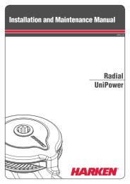
Appendix<br />
Dimensions/Sailmakers's Instructions<br />
Luff Length<br />
Note offsets above and below sail.<br />
If luff of sail is not long enough to put halyard swivel near top of<br />
headstay foil, a pendant must be added (see page 26).<br />
Tack Setback<br />
Note setback for tack shackle and cut the sail accordingly.<br />
A<br />
B<br />
Luff Tape Size<br />
#6 ( 6 /32" or 5 mm) luff tape.<br />
Luff Tape Length<br />
Note feeder height and extend bottom of luff tape downward so it<br />
is below feeder. This will prevent luff tape from catching in feeder<br />
as sail is lowered.<br />
D<br />
E<br />
C<br />
I<br />
H<br />
G<br />
F<br />
Tack and Head Shackles<br />
Make sure tack and head shackles fit<br />
sail rings. Minimum inside dimensions<br />
of standard head and tack shackles are:<br />
Unit A B<br />
2<br />
1 3 /4"<br />
/16"<br />
44 mm 17 mm<br />
3<br />
1 7 /8"<br />
/16"<br />
48 mm 21 mm<br />
B<br />
Sun cover<br />
Sun covers may be installed on either side of sail. Be<br />
sure to match other sails in the customer's inventory.<br />
A<br />
A B C D E F Max* F Min* G H I<br />
7322.20 Short Leg Kit – 300 mm<br />
3 7 /8" 7 5 /16" 2" 9 7 /8" 3 5 /8" 40 3 /4" 25" 12 15 /16" 11 13 /16" 4 15 /16"<br />
99 mm 185 mm 51 mm (250 mm) (97 mm) (1034 mm) (635 mm) (329 mm) (300 mm) (125 mm)<br />
7322.22 Medium Leg Kit –<br />
3 7 /8" 7 5 /16" 2" 9 7 /8" 3 5 /8" 47 7 /8" 32 1 /8" 20 1 /16" 18 15 /16" 12 1 /16"<br />
99 mm 185 mm 51 mm (250 mm) (97 mm) (1217 mm) (817 mm) (510 mm) (480 mm) (307 mm)<br />
7322.21 Long Leg Kit – 600 mm<br />
3 7 /8" 7 5 /16" 2" 9 7 /8" 3 5 /8" 52 9 /16" 36 13 /16" 24 3 /4" 23 5 /8" 16 3 /4"<br />
99 mm 185 mm 51 mm 250 mm 97 mm (1335 mm) (935 mm) (629 mm) (600 mm) (425 mm)<br />
7323.20 Short Leg Kit – 370 mm<br />
5 1 /8" 9 7 /16" 2 1 /8" 11 3 /4" 4 3 /4" 42 15 /16" 27" 16 1 /16" 14 5 /8" 6 1 /2"<br />
130 mm 240 mm 53 mm (298 mm) (121 mm) (1091 mm) (686 mm) (408 mm) (370 mm) (165 mm)<br />
7323.22 Medium Leg Kit –<br />
5 1 /8" 9 7 /16" 2 1 /8" 11 3 /4" 4 3 /4" 51 5 /8" 35 11 /16" 24 3 /4" 23 5 /16" 15 3 /16"<br />
130 mm 240 mm 53 mm (298 mm) (121 mm) (1312 mm) (907 mm) (629 mm) (590 mm) (386 mm)<br />
7323.21 Long Leg Kit – 740 mm<br />
5 1 /8" 9 7 /16" 2 1 /8" 11 3 /4" 4 3 /4" 57 1 /2" 41 9 /16" 30 5 /8" 29 3 /16" 21 1 /16"<br />
130 mm 240 mm 53 mm (298 mm) (121 mm) (1461 mm) (1056 mm) (778 mm) (740 mm) (535 mm)<br />
* E Max and Min depend on foil position at adjuster tube.<br />
<strong>ESP</strong> Unit 2, 3 33<br />
UNIT 2<br />
UNIT 3
Corporate Headquarters<br />
N15W24983 Bluemound Rd, Pewaukee, WI 53072 USA<br />
Telephone: (262) 691-3320 • Fax: (262) 701-5780<br />
Web: www.harken.com • Online Catalog: www.harkenstore.com<br />
Email: harken@harken.com<br />
<strong>Harken</strong> Australia Pty, Ltd.<br />
1B Green Street, Brookvale, N.S.W. 2100, Australia<br />
Telephone: (61) 2-8978-8666 • Fax: (61) 2-8978-8667<br />
Web: harken.com.au • Email: info@harken.com.au<br />
<strong>Harken</strong> France<br />
ZA Port des Minimes, BP 3064, 17032 La Rochelle Cedex 1, France<br />
Telephone: (33) 05.46.44.51.20 • Fax: (33) 05.46.44.25.70<br />
Web: harken.fr • Email: info@harken.fr<br />
<strong>Harken</strong> Italy S.p.A.<br />
Via Marco Biagi, 14, 22070 Limido Comasco (CO) Italy<br />
Telephone: (39) 031.3523511 • Fax: (39) 031.3520031<br />
Web: harken.it • Email: info@harken.it<br />
<strong>Harken</strong> New Zealand, Ltd.<br />
30-36 Fanshawe Street, P.O. Box 1951, Auckland 1001, New Zealand<br />
Telephone: (64) 9-303-3744 • Fax: (64) 9-307-7987<br />
Web: harken.co.nz • Email: harken@harken.co.nz<br />
<strong>Harken</strong> Polska SP ZOO<br />
ul. Rydygiera 8, budynek 3A, lokal 101, I piętro, 01-793 Warszawa, Poland<br />
Tel: +48 22 561 93 93 • Fax: +48 22 839 22 75<br />
Web: harken.pl • Email: polska@harken.pl<br />
<strong>Harken</strong> Sweden AB<br />
Main Office and <strong>Harken</strong> Brandstore: Västmannagatan 81B<br />
SE-113 26 Stockholm Sweden<br />
Telephone: (46) 0303 61875 • Fax: (46) 0303 61876<br />
Mailing address: <strong>Harken</strong> Sweden AB, Box 64, SE -440 30 Marstrand<br />
Web: harken.se • Email: harken@harken.se<br />
<strong>Harken</strong> UK, Ltd.<br />
Bearing House, Ampress Lane, Lymington, Hampshire S041 8LW, England<br />
Telephone: (44) 01590-689122 • Fax: (44) 01590-610274<br />
Web: harken.co.uk • Email: enquiries@harken.co.uk<br />
Please visit: http://www.harken.com/locator.aspx<br />
to locate <strong>Harken</strong> dealers and distributors<br />
Printed in USA 5003 10/13