IC-718 Instruction Manual - ICOM Canada
IC-718 Instruction Manual - ICOM Canada
IC-718 Instruction Manual - ICOM Canada

You also want an ePaper? Increase the reach of your titles
YUMPU automatically turns print PDFs into web optimized ePapers that Google loves.
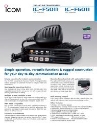
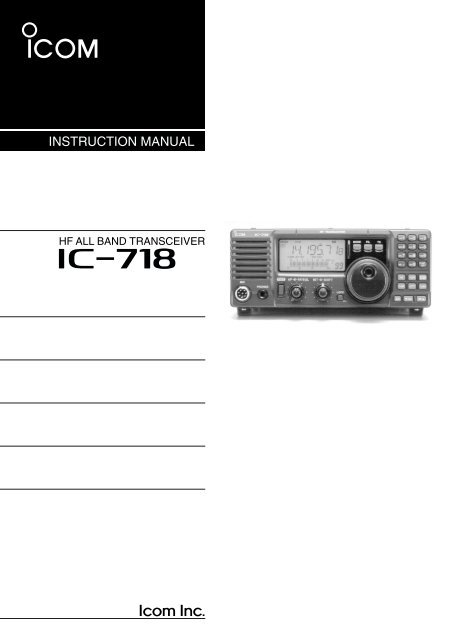
INSTRUCTION MANUAL<br />
HF ALL BAND TRANSCEIVER<br />
i<strong>718</strong><br />
This device complies with Part 15 of the FCC rules. Operation is subject<br />
to the following two conditions: (1) This device may not cause<br />
harmful interference, and (2) this device must accept any interference<br />
received, including interference that may cause undesired operation.
IMPORTANT<br />
EXPL<strong>IC</strong>IT DEFINITIONS<br />
READ THIS INSTRUCTION MANUAL<br />
CAREFULLY before attempting to operate the<br />
transceiver.<br />
SAVE THIS INSTRUCTION MANUAL. This<br />
manual contains important safety and operating instructions<br />
for the <strong>IC</strong>-<strong>718</strong>.<br />
PRECAUTIONS<br />
WORD<br />
R WARNING<br />
CAUTION<br />
NOTE<br />
DEFINITION<br />
Personal injury, fire hazard or electric<br />
shock may occur.<br />
Equipment damage may occur.<br />
Inconvenience only.<br />
No risk of personal injury, fire or<br />
electric shock.<br />
R WARNING HIGH VOLTAGE! NEVER attach<br />
an antenna or internal antenna connector during<br />
transmission. This may result in an electric shock or<br />
burn.<br />
R NEVER apply AC to the [DC13.8V] jack on the<br />
transceiver rear panel. This could cause a fire or ruin<br />
the transceiver.<br />
RNEVER apply more than 16 V DC, such as a 24 V<br />
battery, to the [DC13.8V] jack on the transceiver rear<br />
panel. This could cause a fire or ruin the transceiver.<br />
RNEVER let metal, wire or other objects touch any<br />
internal part or connectors on the rear panel of the<br />
transceiver. This may result in an electric shock.<br />
NEVER expose the transceiver to rain, snow or any<br />
liquids.<br />
AVOID using or placing the transceiver in areas with<br />
temperatures below –10°C (+14°F) or above +60°C<br />
(+140°F). Be aware that temperatures on a vehicle’s<br />
dashboard can exceed 80°C (+176°F), resulting in permanent<br />
damage to the transceiver if left there for extended<br />
periods.<br />
AVOID placing the transceiver in excessively dusty environments<br />
or in direct sunlight.<br />
During mobile operation, DO NOT operate the transceiver<br />
without running the vehicle’s engine. When<br />
transceiver power is ON and your vehicle’s engine is<br />
OFF, the vehicle’s battery will soon become exhausted.<br />
Make sure the transceiver power is OFF before starting<br />
the vehicle. This will avoid possible damage to the<br />
transceiver by ignition voltage spikes.<br />
During maritime mobile operation, keep the transceiver<br />
and microphone as far away as possible from the magnetic<br />
navigation compass to prevent erroneous indications.<br />
BE CAREFUL! The heatsink will become hot when operating<br />
the transceiver continuously for long periods.<br />
BE CAREFUL! If a linear amplifier is connected, set<br />
the transceiver’s RF output power to less than the linear<br />
amplifier’s maximum input level, otherwise, the linear<br />
amplifier will be damaged.<br />
Use Icom microphones only (supplied or optional).<br />
Other manufacturer’s microphones have different pin<br />
assignments, and connection to the <strong>IC</strong>-<strong>718</strong> may damage<br />
the transceiver.<br />
AVOID placing the transceiver against walls or putting<br />
anything on top of the transceiver. This will obstruct<br />
heat dissipation.<br />
i
TABLE OF CONTENTS<br />
1<br />
IMPORTANT .............................................................. i<br />
EXPL<strong>IC</strong>IT DEFINITIONS ........................................... i<br />
PRECAUTIONS ........................................................ i<br />
1 TABLE OF CONTENTS ....................................... 1<br />
SUPPLIED ACCESSORIES ..................................... 1<br />
2 PANEL DESCRIPTION ................................... 2 – 8<br />
■Front panel ........................................................ 2<br />
■Function display ................................................ 5<br />
■Rear panel ......................................................... 6<br />
■Microphone (HM-36) ......................................... 8<br />
3 INSTALLATION AND CONNECTIONS ......... 9 – 14<br />
■Unpacking ......................................................... 9<br />
■Selecting a location ........................................... 9<br />
■Grounding .......................................................... 9<br />
■Antenna connection ........................................... 9<br />
■Required connections ...................................... 10<br />
■Advanced connections ..................................... 11<br />
■Power supply connections ............................... 12<br />
■Liner amplifier connections .............................. 13<br />
■External antenna tuners .................................. 14<br />
4 FREQUENCY SETTING .............................. 15 – 19<br />
■When first applying power ............................... 15<br />
■Initial setting .................................................... 15<br />
■VFO description ............................................... 16<br />
■Frequency setting ............................................ 17<br />
■Dial lock function ............................................. 19<br />
5 RECEIVE AND TRANSMIT ......................... 20 – 34<br />
■Mode selection ................................................ 20<br />
■Squelch and RF gain ....................................... 20<br />
■Function for receive ......................................... 21<br />
■DSP function (option) ...................................... 23<br />
■Filter selection ................................................. 24<br />
■Filter setting ..................................................... 25<br />
■Function for transmit ........................................ 26<br />
■Split frequency operation ................................. 30<br />
■SWR ................................................................ 30<br />
■Function for CW .............................................. 31<br />
■Function for RTTY ........................................... 33<br />
6 MEMORY OPERATION ............................... 35–38<br />
■Memory channels ............................................ 35<br />
■Memory channel selection ............................... 35<br />
■Memory channel programming ........................ 36<br />
■Frequency transferring .................................... 37<br />
■Memory clearing .............................................. 38<br />
7 SCANS ........................................................ 39–40<br />
■Scan types ....................................................... 39<br />
■Preparation ...................................................... 39<br />
■Programmed scan operation ........................... 40<br />
■Memory scan operation ................................... 40<br />
8 SET MODE .................................................. 41–47<br />
■General ............................................................ 41<br />
■Quick set mode items ................................. 42-43<br />
■Initial set mode items ................................. 44-47<br />
9 INSTALLATION AND CONNECTIONS ....... 48–51<br />
■Opening the transceiver’s case ....................... 48<br />
■Optional bracket and carrying handle............... 48<br />
■CR-338 HIGH STABILITY CRYSTAL UNIT .......... 49<br />
■UT-102 VO<strong>IC</strong>E SYNTHESIZER UNIT .................. 49<br />
■UT-106 DSP RECEIVE UNIT ............................. 50<br />
■Optional IF filters ............................................. 50<br />
■AT-180 internal switch description ................... 51<br />
10 MAINTENANCE ........................................ 52–53<br />
■Troubleshooting ............................................... 52<br />
■Fuse replacement ............................................ 53<br />
■Resetting the CPU ........................................... 53<br />
11 SPECIF<strong>IC</strong>ATIONS ........................................... 54<br />
12 OPTIONS .................................................. 55–56<br />
13 CONTROL COMMAND ............................ 57–58<br />
■Remote jack (CI-V) information ....................... 57<br />
14 INTERNAL VIEWS .......................................... 59<br />
■Top view .......................................................... 59<br />
■Bottom view ..................................................... 59<br />
15 INSTALLATION NOTES .................................. 60<br />
■DECLARATION OF CONFORMITY ................ 61<br />
SUPPLIED ACCESSORIES<br />
The transceiver comes with the following accessories.<br />
Qty.<br />
q DC power cable .................................................... 1<br />
w Hand microphone (HM-36) .................................. 1<br />
e Fuse (FGB 20 A; for DC cable) ............................ 1<br />
r Fuse (FGB 4 A; internal use) ............................... 1<br />
q<br />
w<br />
e<br />
r<br />
1
2<br />
PANEL DESCRIPTION<br />
■ Front panel<br />
Speaker<br />
Function Display<br />
@1 @0 !9 !8 !7<br />
<strong>IC</strong>-<strong>718</strong><br />
MODE FIL TS<br />
V/M 1<br />
MW4<br />
A=B2<br />
M-CL5<br />
A/B 3<br />
M V6<br />
SPL7<br />
NR .<br />
SCN8<br />
ANF 0<br />
VOX9<br />
F-INP<br />
ENT<br />
q<br />
w<br />
M<strong>IC</strong><br />
PHONES<br />
PWR<br />
AF<br />
RF/SQL<br />
RIT<br />
SHIFT<br />
LOCK<br />
NB COMP<br />
P.AMP ATT<br />
CH √ DN<br />
SET<br />
TUNER<br />
UP∫<br />
!6<br />
!5<br />
!4<br />
!3<br />
!2<br />
e<br />
r t<br />
y u<br />
i<br />
o<br />
!0<br />
!1<br />
2<br />
q POWER SWITCH [PWR]<br />
➥Push momentarily to turn power ON.<br />
• Turn the optional DC power supply ON in advance.<br />
➥Push for 1 sec. to turn power OFF.<br />
➥While pushing and holding [SET], push [PWR] to<br />
enter the initial set mode. (p. 41)<br />
w M<strong>IC</strong>ROPHONE CONNECTOR [M<strong>IC</strong>]<br />
Accepts supplied or optional microphone.<br />
• See p. 55 for appropriate microphones.<br />
• See p. 8 for microphone connector information.<br />
e HEADPHONE JACK [PHONES] (p. 11)<br />
Accepts headphones (8 Ω).<br />
•When headphones are connected, the internal speaker<br />
or connected external speaker does not function.<br />
r AF CONTROL [AF] (inner control)<br />
Varies the audio output level from the speaker.<br />
t RF GAIN/SQUELCH CONTROL [RF/SQL]<br />
(outer control; pgs. 20, 44)<br />
Adjusts the squelch threshold level. The squelch removes<br />
noise output from the speaker (closed condition)<br />
when no signal is received.<br />
•The squelch is available for all modes.<br />
•The control can be set as the squelch plus RF gain controls<br />
or squelch control only (RF gain is fixed at maximum)<br />
in initial set mode.<br />
y RIT CONTROLS [RIT] (Inner control; p. 21)<br />
➥Shifts the receive frequency without changing the<br />
transmit frequency.<br />
•Rotate the control clockwise to incerase the frequency,<br />
or rotate the control counterclockwise to decrease the<br />
frequency. “ ” appears on the display.<br />
•The shift frequency range is ±1.2 kHz.<br />
u IF SHIFT CONTROLS [SHIFT] (Outer control; p.<br />
21)<br />
Shifts the center frequency of the receivers’s IF<br />
pass-band.<br />
• Rotate the control colckwise to shift the center frequency<br />
higher, or rotate the control counterclockwise to shift the<br />
center frequency lower.<br />
i LOCK SWITCH [LOCK] (p. 19)<br />
Push momentarily to turn the dial lock function ON<br />
and OFF.<br />
• The dial lock function electronically locks the main dial.<br />
• When the optional UT-102 VO<strong>IC</strong>E SYNTHESIZER UNIT is<br />
installed (p. 49), push for 1 sec. to have the frequency,<br />
etc. announced.<br />
• UT-102 operation can be adjusted in initial set mode<br />
(p. 46).<br />
o MAIN DIAL<br />
Changes the displayed frequency, selects quick/initial<br />
set mode items, etc.<br />
!0 PREAMP SWITCH [P.AMP] (p. 21)<br />
Push momentarily to turn the preamp ON or OFF.<br />
!1 CH SWITCH [CH] (p. 35)<br />
Push momentarily to turn the memory channel select<br />
function ON or OFF.<br />
•[MEMO] blinks while memory channel select function is<br />
turned on.
PANEL DESCRIPTION<br />
2<br />
•Push several times (or push and hold) [√ DN]/[UP ∫]<br />
until desired memory channel appears.<br />
•After pushing [F-INP/ENT], push desired memory channel<br />
number from the keypad, then push [FINP/ENT]<br />
again to select the memory channel directory.<br />
• Push [CH] to exit the memory channel select function.<br />
!2 MEMORY CHANNEL (BAND) UP/DOWN<br />
SWITCHES [√DN]/[UP ∫] (p. 35)<br />
➥Push one or more times to select the memory<br />
channel, while [MEMO] indicator is blinking.<br />
➥Push to select a band.<br />
➥Push to select the quick/initial set mode items<br />
while quick/initial set mode is selected.<br />
!3 ATTENUATOR SWITCH [ATT] (p. 22)<br />
Push to toggle the 20 dB attenuator function ON<br />
and OFF.<br />
!4 TUNER SWITCH [TUNER] (pgs. 28, 29)<br />
➥Push momentarily to toggle the automatic antenna<br />
tuner function ON/OFF.<br />
• An optional antenna tuner must be connected.<br />
➥Push for 1 sec. to manually tune the tuner.<br />
• An optional antenna tuner must be connected.<br />
•When the tuner cannot tune the antenna, the tuning circuit<br />
is bypassed automatically after 20 sec.<br />
!5 SET SWITCH [SET]<br />
➥Push for 1 sec. to enter the quick set mode. (p.<br />
41)<br />
➥Pushing and holding [SET], and then push<br />
[POWER] to enter the initial set mode. (p. 41)<br />
➥Push to toggle the meter function; (p. 26)<br />
• PO: indicates the relative RF output power.<br />
• ALC: Indicates ALC level.<br />
•SWR: indicates the SWR over the transmission line.<br />
➥Push [NB] for 1 sec to enter the noise blanker<br />
level setting condition.<br />
!9 QU<strong>IC</strong>K TUNING STEP SWITCH [TS] (pgs. 18,<br />
19)<br />
➥Selects a quick tuning step or turns the quick tuning<br />
step OFF.<br />
•While the quick tuning indicator () is displayed, the<br />
frequency can be changed in kHz step.<br />
➥While the quick tuning step is OFF, it turns the 1<br />
Hz step ON and OFF when pushed for 1 sec.<br />
•1 Hz indication appears and the frequency can be<br />
changed in 1 Hz steps.<br />
➥While the kHz quick tuning step is selected, it enters<br />
tuning step set mode when pushed for 1 sec.<br />
@0 FILTER SWITCH [FIL] (p. 24)<br />
➥Push momentarily to toggle between the pre-programmed<br />
normal, wide and narrow IF filters for<br />
the selected operating mode.<br />
@1 MODE SWITCHES [LSB/USB]/[CW/CW-<br />
R]/[RTTY/RTTY-R]/[AM] (p. 20)<br />
Push to toggle an operating mode.<br />
•Push[MODE] for 1 sec. during SSB mode to toggle between<br />
LSB or USB.<br />
•Push [MODE] for 2 sec. during CW or RTTY mode, to<br />
toggle between CW and CW reverse or RTTY and RTTY<br />
reverse. “ ” appears on the display.<br />
!6 M<strong>IC</strong> COMPRESSOR SWITCH [COMP] (p. 27)<br />
Toggles the Mic. compressor function ON and OFF.<br />
!7 KEYPAD<br />
The keypad can be used for several functions as<br />
discribed below:<br />
•[F-INP/ENT], keypad then [F-INP/ENT].<br />
— Direct frequency input. (pgs. 4, 7)<br />
•[CH], [F-INP/ENT], keypad then [F-INP/ENT] then [V/M]<br />
— Memory channel selection.(pgs. 4, 35)<br />
•[V/M], [A=B], [A/B], [MW], [M-CL], [M≈V], [SPL], [SCAN],<br />
[VOX], [NR] (option) and [ANF] (option) switch. (p. 4)<br />
!8 NOISE BLANKER SWITCH [NB] (p. 22)<br />
➥Toggles the noise blanker ON and OFF. The<br />
noise blanker reduces pulse-type noise such as<br />
that generated by automobile ignition systems.<br />
This function is not effective against non pulsetype<br />
noise.<br />
3
2 PANEL DESCRIPTION<br />
■ Front panel (continued)<br />
MODE FILTER TS<br />
V/M 1<br />
MW4<br />
SPL7<br />
NR .<br />
NB<br />
P.AMP<br />
A=B2<br />
M=CL5<br />
SCN8<br />
ANF 0<br />
COMP<br />
ATT<br />
A/B 3<br />
M V6<br />
VOX9<br />
F-INP<br />
ENT<br />
SET<br />
TUNER<br />
@2<br />
@3<br />
@4<br />
@5<br />
V/M 1<br />
MW4<br />
SPL7<br />
NR .<br />
#3 #2<br />
A=B2<br />
M=CL5<br />
SCN8<br />
ANF 0<br />
@6<br />
A/B 3<br />
M V6<br />
VOX9<br />
F-INP<br />
ENT<br />
#1<br />
#0<br />
@9<br />
@8<br />
@7<br />
K<br />
CH<br />
√DN<br />
UP∫<br />
4<br />
@2 VFO/MEMORY SWITCH/1 [V/M•1] (pgs. 16, 35)<br />
➥Toggles the operating mode between VFO mode<br />
or memory mode when pushed.<br />
@3 MEMORY WRITE SWITCH/4 [MW•4] (p. 36)<br />
➥Stores the displayed frequency and operating<br />
mode into the selected memory channel when<br />
pushed for 1 sec.<br />
@4 SPLIT SWITCH/7 [SPL•7] (p. 30)<br />
Turns the split frequency operation ON or OFF<br />
when pushed.<br />
@5 NR SWITCH/. [NR• . ] (p. 23)<br />
➥Toggles the optional noise reduction function ON<br />
or OFF when pushed. Functions in all modes.<br />
• An optional UT-106 DSP UNIT is required.<br />
• [NR] appears on the display.<br />
➥Enters noise reduction level set mode when<br />
pushed for 1 sec.<br />
@6 ANF SWITCH/0 [ANF•0] (p. 23)<br />
Toggles the Automatic Notch Filter function ON or<br />
OFF. Functions in SSB and AM modes.<br />
• An optional UT-106 DSP UNIT is required.<br />
• [ANF] appears on the display.<br />
@7 FRQUENCY INPUT/ENTER SWITCH<br />
[F-INP/ENT]<br />
➥[F-INP/ENT], then keypad then [F-INP/ENT]<br />
— Direct frequency input. (p. 17)<br />
➥[CH] then [F-INP/ENT], then keypad then [F-<br />
INP/ENT]. Push [CH].<br />
— Direct memory number selection. (p. 35)<br />
@8 SCAN SWITCH/8 [SCAN•8] (p. 39)<br />
➥Push momentarily to start/stop the programmed<br />
scan in VFO mode.<br />
➥Push momentarily to start/stop the memory scan<br />
in memory mode.<br />
@9 VOX SWITCH/9 [VOX•9] (p. 27)<br />
➥Turn the VOX function ON or OFF when pushed<br />
in SSB modes.<br />
#0 M≈V SWITCH/6 [MV•6] (p. 37)<br />
➥Transfers the memory contents to VFO when<br />
pushed for 1 sec.<br />
#1 MEMORY CLEAR SWITCH/5 [M=CL•5] (p. 38)<br />
Clears the selected readout memory channel contents<br />
when pushed for 1 sec. in memory mode.<br />
•[BLANK] appears above the memory channel number.<br />
#2 VFO SELECT SWITCH/3 [A/B•3] (p. 16)<br />
➥Toggles between VFO A or VFO B in VFO mode.<br />
➥Toggles between transmission VFO and reception<br />
VFO during split operation.<br />
#3 VFO EQUALIZATION SWITCH/2 [A=B•2]<br />
Equalize the frequency and operating mode of the<br />
two VFO’s.<br />
• The VFO B frequency and operating mode are equalized<br />
with the VFO A frequency and operating mode.
PANEL DESCRIPTION<br />
2<br />
■ Function display<br />
!9 !8 !7 !6<br />
q<br />
w<br />
e<br />
r<br />
t<br />
y<br />
u<br />
i<br />
!5<br />
!4<br />
!2<br />
!3<br />
o !0 !1<br />
q LOCK IND<strong>IC</strong>ATOR (p. 19)<br />
Appears when the dial lock function is in use.<br />
w RECEIVE IND<strong>IC</strong>ATOR<br />
Appears while receiving a signal or when the<br />
squelch is open.<br />
e TUNE IND<strong>IC</strong>ATOR<br />
Appears while the automatic tuning function is activated.<br />
r TRANSMIT IND<strong>IC</strong>ATOR<br />
Appears while transmitting.<br />
t FUNCTION IND<strong>IC</strong>ATORS<br />
➥“P.AMP” appears when antenna preamp is in<br />
use.<br />
➥“ATT” appears when the attenuator function is in<br />
use.<br />
➥“NB” appears when the Noise Blanker function is<br />
turned ON.<br />
➥“BK” appears when the semi break-in function is<br />
selected in quick set mode.<br />
➥“F-BK” appears when the full break-in function<br />
activates in CW mode. (p. 31)<br />
➥“VOX” appears when the VOX function is selected<br />
in quick set mode.<br />
➥“COM” appears when the speech compressor activates<br />
in SSB mode.<br />
➥“SCAN” appears when the scan function is activated.<br />
• Flashes when scan is paused.<br />
y DSP UNIT IND<strong>IC</strong>ATOR (p. 49)<br />
Appears when an optional UT-106 DSP UNIT is installed.<br />
u AUTOMAT<strong>IC</strong> NOTCH FILTER IND<strong>IC</strong>ATOR (p. 23)<br />
Appears when the optional Automatic Notch Filter<br />
function is in use.<br />
i NOISE REDUCTION IND<strong>IC</strong>ATOR (p. 23)<br />
Appears when the optional Noise Reduction function<br />
is in use.<br />
o SIGNAL/SQL/RF-GAIN METER<br />
➥ Functions as an S-meter while receiving.<br />
➥Functions as a Power, ALC or SWR meter while<br />
transmitting. (p. 26)<br />
!0 VFO/MEMORY IND<strong>IC</strong>ATOR (p. 16)<br />
“VFO A” or “B” appears when VFO mode is selected.<br />
“MEMO” appears when memory mode is selected.<br />
!1 MEMORY CHANNEL NUMBER READOUT (p. 35)<br />
Shows the selected memory channel number.<br />
!2 BLANK IND<strong>IC</strong>ATOR (p. 38)<br />
Shows that the displayed memory channel is not<br />
programmed.<br />
•This indicator appears both in VFO and memory mode.<br />
!3 SPLIT IND<strong>IC</strong>ATORS (p. 30)<br />
Appears when the split frequency operation is in<br />
use.<br />
!4 RIT IND<strong>IC</strong>ATOR (p. 21)<br />
Appears when the RIT function is in use.<br />
!5 FREQUENCY READOUT<br />
Shows the operating frequency.<br />
!6 REVERSE IND<strong>IC</strong>ATOR (p.19)<br />
Appears when the CW reverse or RTTY reverse<br />
mode is selected.<br />
!7 WIDE/NARROW FILTER IND<strong>IC</strong>ATORS (pgs. 24, 25)<br />
➥“ ” appears when the wide IF filter is selected.<br />
➥“ ” appears when the narrow IF filter is selected.<br />
!8 PROGRAMMABLE TUNING STEP IND<strong>IC</strong>ATORS<br />
Appears when the programmable tuning step is selected.<br />
!9 MODE IND<strong>IC</strong>ATORS (p. 20)<br />
Indicates the selected operating mode.<br />
5
2 PANEL DESCRIPTION<br />
■ Rear panel<br />
q w e<br />
13<br />
9 10 11 12<br />
5 6 7 8<br />
1 2 3 4<br />
!0<br />
o<br />
i<br />
u<br />
y<br />
t<br />
r<br />
q ANTENNA TERMINAL [ANT] (p. 10)<br />
Connects a 50 Ω antenna with a PL-259 connector<br />
and a 50 Ω coaxial cable.<br />
w DC POWER SOCKET [DC 13.8V] (p. 12)<br />
Accepts 13.8V DC through the supplied DC power<br />
cable.<br />
u ELECTRON<strong>IC</strong> KEYER JACK [KEY]<br />
Accepts a paddle to activate the internal electronic<br />
keyer.<br />
•Selection between the internal electronic keyer and<br />
straight key operation can be made in initial set mode.<br />
When connecting<br />
a straight key<br />
(⊕)<br />
Rear panel view<br />
e TUNER CONTROL SOCKET [TUNER] (p. 14)<br />
Accepts the control cable from an optional AH-4 AU-<br />
TOMAT<strong>IC</strong> ANTENNA TUNER.<br />
r CI-V REMOTE CONTROL JACK [REMOTE] (p. 57)<br />
Designed for use with a personal computer for remote<br />
operation of transceiver functions.<br />
t EXTERNAL SPEAKER JACK [EXT SP] (p. 11)<br />
Connects an 8 Ω external speaker, if desired.<br />
•When an external speaker is connected, the internal<br />
speaker does not function.<br />
y ACCESSORY SOCKET [ACC] (p. 7)<br />
Enables connection to external equipment such as<br />
an optional AT-180 AUTOMAT<strong>IC</strong> ANTENNA TUNER, a<br />
TNC for data communications or a liner amplifier,<br />
etc.<br />
When connecting<br />
a paddle<br />
i ALC INPUT JACK [ALC]<br />
Connects to the ALC output jack of a non-Icom linear<br />
amplifier.<br />
o SEND CONTROL JACK [SEND] (p. 14)<br />
Goes to ground while transmitting to control external<br />
equipments such as a liner amplifier.<br />
• Max. control level: 16 V DC/2 A<br />
!0 GROUND TERMINAL [GND] (p. 9)<br />
Connects the terminal to ground.<br />
(dot)<br />
(com)<br />
(dash)<br />
6
PANEL DESCRIPTION<br />
2<br />
DACC SOCKET INFORMATION<br />
• ACC socket<br />
ACC PIN # NAME DESCRIPTION SPECIF<strong>IC</strong>ATIONS COLOR<br />
1 8 V Regulated 8 V output.<br />
Output voltage<br />
Output current<br />
: 8 V ±0.3 V<br />
: Less than 10 mA<br />
brown<br />
2 GND Connects to ground. red<br />
3 SEND<br />
Input/output pin.<br />
Goes to ground when transmitting.<br />
When grounded, transmits.<br />
Ground level : –0.5 V to 0.8 V<br />
Input current : Less than 20 mA orange<br />
4 BDT Data line for the optional AT-180. yellow<br />
5 BAND<br />
Band voltage output.<br />
(Varies with amateur band)<br />
Output voltage : 0 to 8.0 V green<br />
13<br />
9 10 11 12<br />
5 6 7 8<br />
1 2 3 4<br />
Rear panel<br />
view<br />
6 ALC ALC voltage input.<br />
Control voltage : –4 to 0 V<br />
Input impedance : More than 10 kΩ<br />
blue<br />
7 NC purple<br />
8 13.8 V 13.8 V output when power is ON. Output current : Max. 1 A gray<br />
9 TKEY Key line for the AT-180. white<br />
10 FSKK RTTY keying input.<br />
Ground level<br />
Input current<br />
: –0.5 to 0.8 V<br />
: Less than 10 mA<br />
black<br />
11 MOD Modulator input.<br />
Input impedance<br />
Input level<br />
: 10 kΩ<br />
: Approx. 100 mV<br />
rms<br />
pink<br />
12 AF<br />
AF detector output.<br />
Fixed, regardless of [AF] position.<br />
Output impedance : 4.7 kΩ<br />
light<br />
Output level : 100 to 300 mV rms blue<br />
13 SQLS<br />
Squelch output.<br />
Goes to ground when squelch opens.<br />
SQL open : Less than 0.3 V/5 mA<br />
SQL closed : More than 6.0 V/100 µA<br />
light<br />
green<br />
•When connecting the ACC conversion cable (OPC-599)<br />
13<br />
9 10 11 12<br />
5 6 7 8<br />
1 2 3 4<br />
2<br />
4<br />
1<br />
8<br />
6<br />
5<br />
3<br />
7<br />
ACC 1<br />
4<br />
2<br />
5<br />
1 3<br />
6 7<br />
➀ FSKK<br />
➁ GND<br />
➂ SEND<br />
➃ MOD<br />
➀ 8 V<br />
➁ GND<br />
➂ SEND<br />
➃ BAND<br />
➄ AF<br />
➅ SQLS<br />
➆ 13.8 V<br />
➇ ALC<br />
➄ ALC<br />
➅ NC<br />
➆ 13.8 V<br />
ACC 2<br />
7
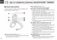
2 PANEL DESCRIPTION<br />
■ Microphone (HM-36)<br />
q<br />
w<br />
q UP/DOWN SWITCHES [UP]/[DN]<br />
Change the selected readout frequency or memory<br />
channel.<br />
•Continuous pushing changes the frequency or memory<br />
channel number continuously.<br />
•The [UP]/[DN] switch can simulate a key paddle. Preset<br />
in the CW PADDL in initial set mode. (p. 31)<br />
w PTT SWITCH<br />
Push and hold to transmit; release to receive.<br />
• M<strong>IC</strong>ROPHONE CONNECTOR<br />
(Front view)<br />
q Microphone input<br />
w +8 V DC output<br />
e Frequency up/down<br />
i Main readout AF output<br />
(varies with [AF]/[BAL])<br />
u GND<br />
(Microphone ground)<br />
y GND (PTT ground)<br />
t PTT<br />
[M<strong>IC</strong>]<br />
PIN NO.<br />
w<br />
e<br />
r<br />
FUNCTION<br />
+8 V DC output<br />
Frequency up<br />
Frequency down<br />
Squelch open<br />
Squelch closed<br />
DESCRIPTION<br />
Max. 10 mA<br />
Ground<br />
Ground through 470 Ω<br />
“LOW” level<br />
“HIGH” level<br />
r Main readout squelch switch<br />
CAUTION: DO NOT short pin 2 to ground as this<br />
can damage the internal 8 V regulator.<br />
• HM-36 SCHEMAT<strong>IC</strong> DIAGRAM<br />
M<strong>IC</strong>ROPHONE<br />
M<strong>IC</strong>ROPHONE CABLE M<strong>IC</strong>ROPHONE PLUG<br />
10µ<br />
+<br />
2k<br />
4700p<br />
+<br />
M<strong>IC</strong><br />
ELEMENT<br />
0.33µ<br />
4700p<br />
DOWN<br />
UP<br />
q u<br />
w i y<br />
e t r<br />
PTT<br />
RECEIVE<br />
TRANSMIT<br />
470<br />
8
INSTALLATION AND CONNECTIONS<br />
3<br />
■ Unpacking<br />
After unpacking, immediately report any damage to the<br />
delivering carrier or dealer. Keep the shipping cartons.<br />
For a description and a diagram of accessory equipment<br />
included with the <strong>IC</strong>-<strong>718</strong>, see ‘Supplied accessories’<br />
on p. 1 of this manual.<br />
■ Selecting a location<br />
Select a location for the transceiver that allows adequate<br />
air circulation, free from extreme heat, cold, or<br />
vibrations, and away from TV sets, TV antenna elements,<br />
radios and other electro-magnetic sources.<br />
The base of the transceiver has an adjustable stand<br />
for desktop use. Set the stand to one of two angles depending<br />
on your operating conditions.<br />
■ Antenna connection<br />
For radio communications, the antenna is of critical importance,<br />
along with output power and sensitivity. Select<br />
antenna(s), such as a well-matched 50 Ω antenna,<br />
and feedline. 1.5:1 or better of Voltage Standing Wave<br />
Ratio (VSWR) is recommended for your desired band.<br />
Of course, the transmission line should be a coaxial<br />
cable.<br />
CAUTION: Protect your transceiver from lightning<br />
by using a lightning arrestor.<br />
PL-259 CONNECTOR INSTALLATION EXAMPLE<br />
q<br />
w<br />
Coupling ring<br />
30 mm<br />
10 mm (soft solder)<br />
10 mm<br />
1–2 mm<br />
Soft<br />
solder<br />
Slide the coupling ring<br />
down. Strip the cable<br />
jacket and soft solder.<br />
Strip the cable as<br />
shown at left. Soft<br />
solder the center conductor.<br />
e<br />
solder solder<br />
Slide the connector<br />
body on and solder it.<br />
r<br />
Screw the coupling<br />
ring onto the<br />
connector body.<br />
■ Grounding<br />
To prevent electrical shock, television interference<br />
(TVI), broadcast interference (BCI) and other problems,<br />
ground the transceiver through the GROUND<br />
terminal on the rear panel.<br />
For best results, connect a heavy gauge wire or strap<br />
to a long earth-sunk copper rod. Make the distance between<br />
the [GND] terminal and ground as short as possible.<br />
RWARNING: NEVER connect the [GND]<br />
terminal to a gas or electric pipe, since the connection<br />
could cause an explosion or electric shock.<br />
30 mm ≈ 9 ⁄8 in 10 mm ≈ 3 ⁄8 in 1–2 mm ≈ 1 ⁄16 in<br />
Antenna SWR<br />
Each antenna is tuned for a specified frequency<br />
range and SWR may be increased out-of-range.<br />
When the SWR is higher than approx. 2.0:1, the<br />
transceiver’s power drops to protect the final transistor.<br />
In this case, an antenna tuner is useful to match<br />
the transceiver and antenna. Low SWR allows full<br />
power for transmitting even when using the antenna<br />
tuner. The <strong>IC</strong>-<strong>718</strong> has an SWR meter to monitor the<br />
antenna SWR continuously.<br />
9
3 INSTALLATION AND CONNECTIONS<br />
■ Required connections<br />
•Front panel<br />
M<strong>IC</strong>ROPHONES (p. 55)<br />
<strong>IC</strong>-<strong>718</strong><br />
MODE FIL TS<br />
V/M 1<br />
MW4<br />
SPL7<br />
NR .<br />
A=B2<br />
M-CL5<br />
SCN8<br />
ANF 0<br />
A/B 3<br />
M V6<br />
VOX9<br />
F-INP<br />
ENT<br />
M<strong>IC</strong><br />
PHONES<br />
PWR<br />
AF<br />
RF/SQL<br />
RIT<br />
SHIFT<br />
NB<br />
P.AMP<br />
COMP<br />
ATT<br />
SET<br />
TUNER<br />
LOCK<br />
HM-36<br />
SM-20<br />
CH<br />
∫<br />
DN<br />
UP<br />
√<br />
•Rear panel<br />
ANTENNA (p. 56)<br />
[Example]: 1.8–30 MHz bands<br />
AH-710<br />
approx. 24.5 m; 80.3 ft<br />
DC POWER SUPPLY<br />
PS-85<br />
GROUND (p. 9)<br />
CW KEY<br />
Use the heaviest gauge wire<br />
or strap available and make<br />
the connection as short as<br />
possible.<br />
Grounding prevents electrical<br />
shocks, TVI and other<br />
problems.<br />
A straight key can be used when the<br />
internal electronic keyer is turned<br />
OFF in “CW PADDL” in initial set<br />
mode. (p. 31)<br />
10
INSTALLATION AND CONNECTIONS<br />
3<br />
■ Advanced connections<br />
•Front panel<br />
<strong>IC</strong>-<strong>718</strong><br />
MODE FIL TS<br />
V/M 1<br />
MW4<br />
A=B2<br />
M-CL5<br />
A/B 3<br />
M V6<br />
SPL7<br />
NR .<br />
SCN8<br />
ANF 0<br />
VOX9<br />
F-INP<br />
ENT<br />
M<strong>IC</strong><br />
The AFSK modulation signal can be<br />
input from [M<strong>IC</strong>]. (p. 33)<br />
M<strong>IC</strong><br />
PHONES<br />
PWR<br />
AF<br />
RF/SQL<br />
RIT<br />
SHIFT<br />
LOCK<br />
CH<br />
NB<br />
P.AMP<br />
∫<br />
COMP<br />
ATT<br />
DN<br />
SET<br />
TUNER<br />
UP ∫<br />
HEADPHONES<br />
•Rear panel<br />
AH-4 (p. 55)<br />
[REMOTE] (p. 57)<br />
Used for computer control and transceive operation.<br />
with<br />
AH-2b<br />
or long wire<br />
ANTENNA (p. 13)<br />
Connects a liner amprifier, etc.<br />
ACC SOCKETS (p. 7)<br />
[SEND], [ALC]<br />
(p. 14)<br />
Used for connecting a<br />
non-Icom linear amplifier.<br />
EXTERNAL SPEAKER (p. 55)<br />
SP-21, etc<br />
11
13<br />
9 10 11 12<br />
5 6 7 8<br />
1 2 3 4<br />
13<br />
9 10 11 12<br />
5 6 7 8<br />
1 2 3 4<br />
3 INSTALLATION AND CONNECTIONS<br />
■ Power supply connections<br />
Use an optional PS-85 DC POWER SUPPLY when operating<br />
the <strong>IC</strong>-<strong>718</strong> with AC power. Refer to the diagrams<br />
below.<br />
CAUTION: Before connecting the DC power<br />
cable, check the following important items. Make<br />
sure:<br />
•The [POWER] switch is OFF.<br />
•Output voltage of the power source is 12–15 V<br />
when you use a non-Icom power supply.<br />
•DC power cable polarity is correct.<br />
Red : positive + terminal<br />
Black : negative _ terminal<br />
CONNECTING PS-85 DC POWER SUPPLY<br />
PS-85<br />
Connect to an AC outlet<br />
using the supplied AC cable.<br />
DC power<br />
socket<br />
DC power cable<br />
CONNECTING NON-<strong>IC</strong>OM DC POWER SUPPLY<br />
DC power supply<br />
AC outlet<br />
DC power<br />
socket<br />
13.8 V 20 A<br />
_ +<br />
AC cable<br />
_ black<br />
Supplied<br />
+red<br />
DC power cable 20 A fuses<br />
CONNECTING A VEH<strong>IC</strong>LE BATTERY<br />
NEVER connect to<br />
a 24 V battery.<br />
NOTE: Use terminals for<br />
the cable connections.<br />
Grommet<br />
_ black<br />
+ red<br />
Crimp<br />
12 V<br />
battery<br />
Supplied<br />
DC power cable<br />
Solder<br />
12<br />
Fuses<br />
NEVER connect to a battery without supplied DC fuses,<br />
otherwise the fire hazard may occur.
13<br />
9 10 11 12<br />
5 6 7 8<br />
1 2 3 4<br />
13<br />
9 10 11 12<br />
5 6 7 8<br />
1 2 3 4<br />
INSTALLATION AND CONNECTIONS<br />
3<br />
■ Linear amplifier connections<br />
CONNECTING THE <strong>IC</strong>-PW1<br />
Remote control cable (supplied with the <strong>IC</strong>-PW1)<br />
To an<br />
antenna<br />
ACC-1<br />
ACC cable (supplied with the <strong>IC</strong>-PW1)<br />
ANT<br />
REMOTE<br />
INPUT1<br />
OPC-599 conversion cable<br />
(option)<br />
Coaxial cable<br />
(supplied with the <strong>IC</strong>-PW1)<br />
ACC<br />
REMOTE<br />
EXCITER<br />
1 1&2<br />
GND<br />
<strong>IC</strong>-PW1<br />
AC outlet<br />
(Non-European versions : 100–120/220–240 V<br />
European version : 230 V)<br />
Ground<br />
GND<br />
<strong>IC</strong>-<strong>718</strong><br />
CONNECTING THE <strong>IC</strong>-4KL<br />
Coaxial cable (supplied with the <strong>IC</strong>-4KL)<br />
OPC-599 conversion cable<br />
(option)<br />
ACC cable (supplied with the <strong>IC</strong>-4KL)<br />
To an<br />
antenna<br />
ACC<br />
ANT<br />
ACC<br />
<strong>IC</strong>-4KL<br />
Remote<br />
controller<br />
<strong>IC</strong>-4KL<br />
<strong>IC</strong>-<strong>718</strong><br />
Remote control cable<br />
(supplied with the <strong>IC</strong>-4KL)<br />
Ground<br />
AC outlet (220–240 V)<br />
13
13<br />
9 10 11 12<br />
5 6 7 8<br />
1 2 3 4<br />
13<br />
9 10 11 12<br />
5 6 7 8<br />
1 2 3 4<br />
3 INSTALLATION AND CONNECTIONS<br />
CONNECTING A NON-<strong>IC</strong>OM LINER AMPLIFIER<br />
R WARNING:<br />
Set the transceiver output<br />
power and linear amplifier<br />
ALC output level referring to<br />
the linear amplifier instruction<br />
manual.<br />
To an<br />
antenna<br />
RF OUTPUT<br />
RF INPUT<br />
SEND<br />
50 Ω coaxial cable<br />
ANT<br />
<strong>IC</strong>-<strong>718</strong><br />
The ALC input level must be<br />
in the range 0 V to –4 V, and<br />
the transceiver does not accept<br />
positive voltage. Nonmatched<br />
ALC and RF power<br />
settings could cause a fire or<br />
ruin the linear amplifier.<br />
ALC<br />
Non-Icom linear amplifier<br />
SEND<br />
ALC<br />
The specifications for the SEND relay are 16 V<br />
DC 2 A. If this level is exceeded, a large external<br />
relay must be used.<br />
■ External antenna tuners<br />
CONNECTING THE AH-4 (p. 29)<br />
Long wire or optional AH-2b<br />
Coaxial cable (from the AH-4)<br />
Control cable<br />
Ground<br />
<strong>IC</strong>-<strong>718</strong><br />
Ground<br />
AH-4<br />
CONNECTING THE AT-180 (p. 28)<br />
DO NOT! connect AT-180 and AH-4 at the same<br />
time. Both tuners will not function correctly.<br />
Turn the <strong>IC</strong>-<strong>718</strong>’s power OFF when connecting the<br />
AT-180, otherwise, the CPU may malfunction and<br />
the AT-180 may not function properly.<br />
Coaxial cable supplied<br />
with the AT-180<br />
ACC cable supplied with the AT-180<br />
HF<br />
antenna<br />
[ANT] [ACC] AT-180 [ACC]<br />
one of two<br />
connectors<br />
<strong>IC</strong>-<strong>718</strong><br />
Ground<br />
14
FREQUENCY SETTING<br />
4<br />
■ When first applying power (CPU resetting)<br />
Before first applying power, make sure all connections<br />
required for your system are complete by referring<br />
to Chapter 3. Then, reset the transceiver using<br />
the following procedure.<br />
Resetting CLEARS all programmed contents in<br />
memory channels and returns programmed values<br />
in quick/initial set mode to default values.<br />
[PWR]<br />
√<br />
√<br />
[√] [∫]<br />
q Make sure the transceiver power is OFF.<br />
w While pushing and holding [∫ UP] and [√ DN],<br />
push [PWR] for 1 sec. to turn power ON.<br />
•The internal CPU is reset.<br />
•The transceiver displays its initial VFO frequencies<br />
when resetting is complete.<br />
e All quick/initial set mode settings are returned to<br />
default values. (p. 41)<br />
Under cooler temperatures, the LCD may appear<br />
dark and unstable after turning power ON. This is<br />
normal and does not indicate any equipment malfunction.<br />
■ Initial settings<br />
After resetting the transceiver, set controls and<br />
switches as shown in the figure below.<br />
CCW<br />
: counterclockwise<br />
[METER]: Po<br />
[NB], [COMP]:<br />
OFF<br />
[POWER]: OFF<br />
∫<br />
∫<br />
[P.AMP],<br />
[ATT],: OFF<br />
[AF]: Max. CCW<br />
[LOCK]: OFF<br />
[RF/SQL]: 12 o'clock<br />
[RIT]: Center<br />
[IF SHIFT]: Center<br />
Turn power ON, then check the display. If any of the<br />
following indicators appear, turn them OFF as follows:<br />
•Quick tuning step indicator “▼” : Push [TS].<br />
•1 Hz frequency readout : Push [TS] for 1 sec.<br />
(while quick tuning<br />
step is OFF)<br />
•RIT indicator “ RIT ” : Center.<br />
•Split indicator “ ” : Push [SPL].<br />
15
4 FREQUENCY SETTING<br />
■ VFO description<br />
VFO is an abbreviation of Variable Frequency Oscillator,<br />
and traditionally refers to an oscillator.<br />
The <strong>IC</strong>-<strong>718</strong> VFO can store a frequency and an operating<br />
mode.<br />
You can call up a desired frequency to the VFO with<br />
the keypad or the memory transfer function (see p.<br />
37). You can also change the frequency with the tuning<br />
dial and select the operating mode with the [MODE]<br />
switch or call up previously accessed frequency and<br />
modes with the band stacking register (p. 18).<br />
The <strong>IC</strong>-<strong>718</strong> has two VFOs, specially suited for split frequency<br />
opration. The VFOs are called VFO A and VFO<br />
B. You can call up the desired VFO.<br />
•Differences between VFO mode and memory mode<br />
VFO MODE<br />
Each VFO shows a frequency and operating mode. If<br />
the frequency or operating mode is changed, the VFO<br />
automatically memorizes the new frequency or new<br />
operating mode.<br />
When the VFO is selected from another VFO or<br />
memory mode, the last-used frequency and operating<br />
mode for that VFO appears.<br />
[EXAMPLE]<br />
VFO is selected.<br />
MEMORY MODE (pgs. 35-38)<br />
Each memory channel shows a frequency and operating<br />
mode like a VFO. Even if the frequency or mode<br />
is changed, the memory channel does not memorize<br />
the new frequency or operating mode.<br />
When the memory channel is selected from another<br />
memory channel or VFO mode, the memorized frequency<br />
and operating mode appear.<br />
[EXAMPLE]<br />
Memory channel 1<br />
is selected.<br />
The frequency<br />
is changed.<br />
The frequency<br />
is changed.<br />
Memory mode<br />
is selected.<br />
Another memory<br />
channel is selected.<br />
VFO is selected<br />
again.<br />
Memory channel 1<br />
is selected again.<br />
Changed frequency (14.123 MHz) appears.<br />
Changed frequency (14.123 MHz) does not appear and<br />
memorized frequency (14.100 MHz) appears instead.<br />
16
FREQUENCY SETTING<br />
4<br />
■ Frequency setting<br />
DUsing the tuning dial<br />
qPush [∫UP] or [√DN] one or more times to<br />
select the desired ham band.<br />
• For general coverage receiver use<br />
The <strong>IC</strong>-<strong>718</strong> has a general coverage receiver band.<br />
qPush [∫UP] or [√DN] one or more times to select<br />
the general coverage receiver band.<br />
wSelect the desired operating mode with the mode<br />
switch. (p. 20).<br />
eRotate the tuning dial to set the desired frequency<br />
Note: Even if you select the ham band, you can set<br />
the transceiver to the general coverage frequency.<br />
When the displayed frequency exits the transmit frequency<br />
range (ham band), a band edge beep may be<br />
emitted (depends on initial set mode programming).<br />
DDirect frequency entry with keypad<br />
The transceiver has a keypad for direct frequency<br />
entry as described below.<br />
q Push [F-INP/ENT], then push the numeral keys on<br />
the keypad to enter the MHz digits for the desired<br />
frequency.<br />
•If a key is mistakenly pushed, push [SET] (or any key<br />
except keypad) and start again from the beginning.<br />
•When entering the same MHz digits as the displayed<br />
frequency, this step can be skipped.<br />
w Push [•] on the keypad.<br />
e Push the numeral keys to enter the frequency digits<br />
below 1 MHz.<br />
•If a key is mistakenly pushed, push [SET] (or any key<br />
except keypad) and start again from the beginning.<br />
r Push [F-INP/ENT] to set the input frequency.<br />
•When pushing [F-INP/ENT] after entering the MHz digits,<br />
zeros are automatically entered for the kHz digits.<br />
[EXAMPLE]<br />
•Start<br />
F-INP<br />
ENT<br />
•To set to 21.025 MHz<br />
A=B2<br />
V/M 1 NR ANF 0 A=B2<br />
F-INP<br />
M=CL5 ENT<br />
•To set to 706 KHz (0.706 MHz)<br />
ANF 0<br />
NR 7<br />
<br />
SPL ANF0 M V6<br />
F-INP<br />
ENT<br />
•To set to 7 MHz<br />
SPL7<br />
F-INP<br />
ENT<br />
•To change 14.195 to 14.850 MHz<br />
NR<br />
SCN8<br />
M=CL5<br />
F-INP<br />
ENT<br />
17
4 FREQUENCY SETTING<br />
DBand stacking resister<br />
The band stacking register automatically stores the<br />
last frequency and mode used for each band. This is<br />
convenient for contest operation, etc. The tables<br />
below shows the band stacking register default settings<br />
for each band.<br />
BAND BAND BAND<br />
1.9 MHz 1.91000 MHz CW<br />
3.5 MHz 3.55000 MHz LSB<br />
7 MHz 7.05000 MHz LSB<br />
10 MHz 10.12000 MHz CW<br />
14 MHz 14.10000 MHz USB<br />
General 15.10000 MHz USB<br />
BAND BAND BAND<br />
18 MHz 18.10000 MHz USB<br />
21 MHz 21.20000 MHz USB<br />
24 MHz 24.95000 MHz USB<br />
28 MHz 28.50000 MHz USB<br />
29 MHz 29.50000 MHz USB<br />
DBand selection<br />
All HF ham bands and a general coverage receiver<br />
band are included in the <strong>IC</strong>-<strong>718</strong>.<br />
Push [∫ UP]/[√DN] to select the desired band.<br />
•Pushing [∫ UP]/[√ DN] continuously scrolls through the<br />
available bands.<br />
Note: For example, if 6.10000 MHz is resistered as<br />
the General coverage frequency, then the General<br />
coverage band automatically positions itself between<br />
3.5 MHz and 7 MHz band.<br />
General (new)<br />
√ DN<br />
UP∫<br />
General (old)<br />
DProgrammable tuning steps<br />
Programmable tuning steps are available to suit your<br />
operating requirements.<br />
These tuning steps are:<br />
•Selectable from 0.1, 1, 5, 9, 10, 100 kHz<br />
q Push [TS], the programmable tuning step indicator,<br />
“,” then appears above the 1 kHz.<br />
•Rotating the tuning dial changes the frequency according<br />
to the set tuning step.<br />
w Push [TS] for 2 sec. while the programmable tuning<br />
step indicator appears to enter the tuning step<br />
set mode.<br />
e Rotate the tuning dial to set the desired tuning<br />
step.<br />
r Push [TS] to exit the tuning step set mode.<br />
t Rotate the tuning dial to change the frequency according<br />
to the set tuning step.<br />
Programmable tuning<br />
step indicator<br />
10 KHz tuning steps is<br />
selected.<br />
18
FREQUENCY SETTING<br />
4<br />
D1 Hz and 10 Hz tuning steps<br />
When the programmable tuning step, “,” disappear,<br />
rotating the tuning dial changes the frequency in increments<br />
of 1 or 10 Hz.<br />
q Push [TS] one or more times until the programmable<br />
tuning step indicator “” disappears.<br />
w Push [TS] for 1 sec. to toggle between the 1 and<br />
10 Hz step settings.<br />
•When the 1 Hz step is selected, the 1 Hz digit appears<br />
in the frequency indication; when the 10 Hz step is selected,<br />
the 1 Hz digit disappears from the frequency indication.<br />
Push<br />
TS<br />
for 1 sec.<br />
Rotating the tuning dial<br />
changes the frequency<br />
in 10 Hz steps.<br />
Rotating the tuning dial<br />
changes the frequency<br />
in 1 Hz steps.<br />
[TS] SWITCH FLOW CHART<br />
10 Hz tuning<br />
Programmable step tuning<br />
(100 Hz –100 kHz)<br />
1 sec.<br />
momentarily<br />
1 sec.<br />
1 sec.<br />
momentarily<br />
1 Hz tuning<br />
Selectable for each mode.<br />
■ Dial lock function<br />
The dial lock function prevents accidental changes<br />
caused by the tuning dial. The lock function electronically<br />
locks the dial.<br />
“LOCK” appears while the lock<br />
function is activated.<br />
Push [LOCK] momentarily to toggle the lock function<br />
ON and OFF.<br />
•“LOCK” appears in the function display while the lock function<br />
is activated.<br />
19
5<br />
RECEIVE AND TRANSMIT<br />
■ Mode selection<br />
The following modes are available in the <strong>IC</strong>-<strong>718</strong>:<br />
SSB (LSB/USB), CW, CW REV (CW reverse), RTTY,<br />
RTTY REV (RTTY reverse)and AM.<br />
OPERATING MODE SELECTION<br />
➥ Push [MODE] one or more times to select desired<br />
operation mode.<br />
➥ Push [MODE] for 1 sec. to toggle between USB<br />
and LSB. (SSB mode only)<br />
➥ Push [MODE] for 1 sec. to toggle between CW and<br />
CW reverse or RTTY and RTTY reverse. (CW and<br />
RTTY mode only)<br />
•The selected mode is indicated in the function display.<br />
USB<br />
CW<br />
RTTY<br />
AM<br />
LSB<br />
CW<br />
RTTY<br />
MODE<br />
Push<br />
momentarily<br />
MODE<br />
Push<br />
for 1 sec.<br />
Note: If desired mode cannot be selected, it’s use<br />
may inhibited by initial set mode. (p. 44)<br />
■ RF gain and Squelch<br />
The <strong>IC</strong>-<strong>718</strong> uses the same control, [RF/SQL], to adjust<br />
either the RF gain or the squelch. [RF/SQL] adjusts<br />
either the RF gain or the squelch depending on<br />
the operating mode selected and the condition of the<br />
RF/SQL item in initiaset mode (p. 44).<br />
•[RF/SQL] control priority<br />
Set mode<br />
setting<br />
rS (RF/SQL)<br />
(default)<br />
USB, LSB,<br />
CW, RTTY<br />
RF/SQL<br />
AM<br />
RF/SQL<br />
•When set as the [RF/SQL] control<br />
Maximum RF gain<br />
Squelch is open.<br />
RF gain adjustable<br />
range<br />
•When set as the [SQL] control<br />
S-meter squelch<br />
threshold<br />
S-meter squelch<br />
At (AUTO) RF GAIN SQL*<br />
Sq (SQL)<br />
SQL*<br />
SQL*<br />
* The RF gain is set to maximum level when the [RF/SQL]<br />
is set as [SQL] control.<br />
Squelch is open.<br />
Shallow<br />
Deep<br />
S-meter squelch<br />
threshold<br />
S-meter squelch<br />
The RF (Radio Frequency) gain is used to adjust the<br />
receiver gain.<br />
•Shallow rotation moves the S-meter to the right indicating<br />
the signal strength which can be received.<br />
The recommended position for RF gain is the 12<br />
o’clock position since this sets RF gain to the max.<br />
The SQUELCH removes noise output from the<br />
speaker (closed condition) when no signal is received.<br />
The squelch is available for the other modes.<br />
•A segment appears in the S-meter to indicate the S-meter<br />
squelch level.<br />
•When set as the [RF] control<br />
Maximum RF gain<br />
Adjustable range<br />
Minimum RF gain<br />
20
RECEIVE AND TRANSMIT<br />
5<br />
■ Function for receive<br />
ï IF shift function<br />
The IF shift function electronically narrows the passband<br />
frequency of the IF (intermediate frequency)<br />
and cuts out higher or lower frequency components<br />
of the IF to reject interference. The function shifts the<br />
IF frequency up to ±1.2 KHz in SSB/CW/RTTY<br />
modes and up ±250 Hz in CW-narrow/RTTY narrow<br />
modes. The IF shift is not available in AM mode.<br />
IF SHIFT OPERATION EXAMPLE<br />
•Adjust the [SHIFT] control for a minimum interference<br />
signal level.<br />
•When IF shift is used, the audio tone may be<br />
changed.<br />
•Set the IF shift control to its center position when<br />
there is no interference.<br />
Both controls at<br />
center position<br />
SHIFT<br />
Cutting a lower<br />
passband<br />
SHIFT<br />
Cutting higher<br />
passbands<br />
SHIFT<br />
Interference<br />
Passband<br />
Passband<br />
Interference<br />
IF center frequency<br />
Desired signal<br />
Desired signal<br />
ï RIT function<br />
The RIT (Receive Incremental Tuning) function compensates<br />
for off-frequencies of communicating stations.<br />
The function shifts the receive frequency up to<br />
1.2 KHz without moving the transmit frequency.<br />
qRotate the RIT control to cancel the off-frequencies.<br />
•“ ” appears on the display.<br />
• The transmit frequencies are not shifted.<br />
wTo cancel the RIT function,<br />
rotate the RIT control<br />
to the center<br />
position.<br />
•“ ” disappears.<br />
RIT off position<br />
ï Preamp<br />
The preamp amplifies received signals in the front<br />
end circuit to improve the S/N ratio and sensitivity.<br />
Turn this function ON when receiving weak signals.<br />
➥ Push [P.AMP] to toggle between preamp or turn<br />
the preamp OFF.<br />
• Preamp functions below 1.59999 MHz, but sensitivity<br />
may reduce in some cases.<br />
Appears when the<br />
preamp ON.<br />
21
5 RECEIVE AND TRANSMIT<br />
ï Attenuator<br />
The attenuator prevents desired signals from distorting<br />
when very strong signals are near the desired frequency<br />
or when very strong electric fields, such as<br />
from broadcasting stations, are near your location.<br />
➥ Push [ATT] to toggle the 20 dB attenuator function<br />
ON and OFF.<br />
•“ATT” appears when the attenuator is turned ON.<br />
Appears when the<br />
attenuator ON.<br />
ï Noise blanker<br />
The noise blanker reduces pulse-type noise such as<br />
that generated by automobile ignition systems.<br />
q Push the [NB] switch to turn the noise blanker ON<br />
or OFF.<br />
w Push the [NB] for 1 sec. to enter the noise blanker<br />
level setting condition.<br />
e Rotate the tuning dial to adjust the noise blanker<br />
level.<br />
r Push [NB] to exit the setting condition.<br />
t Push [NB] again to turn the noise blanker function<br />
OFF.<br />
• [NB] indicator disappears.<br />
<br />
[NB] switch<br />
<br />
•When using the noise blanker, received signals<br />
may be distorted if they are excessively strong.<br />
•The noise blanker function in AM mode can be<br />
deactivated depending on initial set mode setting.<br />
(p. 45)<br />
ï Peak meter hold<br />
The peak meter hold function freezes the highest displayed<br />
bar segment in any meter function for about<br />
0.5 sec. so that you can more easily read the meter.<br />
This function can be turned ON and OFF in initial set<br />
mode (p. 45).<br />
Initial reception of a signal<br />
results in an S-meter reading<br />
of 40 dB.<br />
The highest indicated bar<br />
remains displayed for 0.5 sec.<br />
even when the signal strength<br />
decreases.<br />
22
RECEIVE AND TRANSMIT<br />
5<br />
■ DSP function (Requires an optional UT-106 DSP UNIT)<br />
ï NR (Noise reduction) function<br />
When an optional UT-106 is installed (DSP appears<br />
in the function display), noise reduction function can<br />
be used.<br />
•Noise reduction example<br />
Noise reduction OFF<br />
Noise reduction activated<br />
The noise reduction function reduces noise components<br />
and picks out desired signals which are buried<br />
in noise. The received AF signals are converted to<br />
digital signals and then the desired signals are separated<br />
from the noise.<br />
Noise components<br />
Desired<br />
signal (CW)<br />
q Push [NR] to turn the noise reduction ON.<br />
•[NR] indicator appears.<br />
Higher setting of the [NR] level results in audio signal<br />
masking or distortion. Set the [NR] level for<br />
maximum clarity. The noise reduction function is<br />
available in all modes.<br />
w Push [NR] for 1 sec. to enter the noise reduction<br />
level setting condition.<br />
e Rotate the tuning dial to adjust the noise reduction<br />
level.<br />
r Push [NR] to exit the setting condition.<br />
t Push [NR] again to turn the noise reduction OFF.<br />
•[NR] indicator disappears.<br />
ï ANF (Automatic Notch Filter) function<br />
When an optional UT-106 is installed (DSP appears<br />
in the function display), an auto notch function can be<br />
used.<br />
Auto notch OFF<br />
Auto notch ON<br />
The function automatically attenuates more than 3<br />
beat tones, tuning signals, etc., even if they are moving.<br />
Desired<br />
signal (AF)<br />
Desired<br />
signal (AF)<br />
The auto notch functions in SSB mode only.<br />
q Select SSB mode.<br />
w Push [ANF] to turn the auto notch function ON.<br />
•[ANF] indicator appears.<br />
e Push [ANF] again to cancel the function.<br />
•[ANF] indicator disappears.<br />
Unwanted tone<br />
frequency<br />
Particular frequency<br />
is attenuated<br />
23
5 RECEIVE AND TRANSMIT<br />
■ Filter selection<br />
The filter selection switches the IF passband width as<br />
shown in the table at right.<br />
The filter selection is automatically memorized in<br />
each mode.<br />
q Select the desired mode with the mode switches.<br />
w Push [FIL] one or more times to select the desired<br />
filter combination.<br />
•ã or ç does not appear while in normal IF filter mode.<br />
• ç appears when the wide IF filter is selected.<br />
• ã appears when the narrow IF filter is selected.<br />
When an optional filter is installed, set the optional<br />
filter in initial set mode. An optional filter is not selected<br />
by default.<br />
•Filter construction<br />
•Optional filter variations<br />
Name Band width<br />
FL-52A 500 Hz/-6dB<br />
FL-53A 250 Hz/-6dB<br />
FL-96 2.8 KHz/-6dB<br />
FL-222 1.8 KHz/-6dB<br />
FL-257 3.3 KHz/-6dB<br />
Through<br />
Mode<br />
CW/RTTY-N<br />
CW/RTTY-N<br />
SSB-W<br />
SSB-N<br />
SSB-W<br />
2nd IF signal<br />
CFWS450HT (6 kHz)***<br />
FL-65 (2.4 kHz)*<br />
2nd IF signal/DET<br />
FL-257 (3.3 kHz)**<br />
FL-96 (2.8 kHz)**<br />
FL-222 (1.8 kHz)**<br />
FL-52A (500 Hz)**<br />
FL-53A (250 Hz)**<br />
* AM; Narrow,<br />
SSB/CW/RTTY; Normal<br />
** OPTION<br />
*** AM; Normal,<br />
SSB/CW/RTTY; Wide<br />
•Filter selection table<br />
no FL-52A FL-53A FL-96 FL-222 FL-257<br />
SSB<br />
WIDE 6 K* 6 K* 6 K*<br />
6 K*<br />
6 K*<br />
6 K*<br />
2.8 K<br />
3.3 K<br />
NORMAL 2.4 K 2.4 K 2.4 K 2.4 K 2.4 K 2.4 K<br />
NARROW 500* 250* 1.8 K<br />
CW<br />
6 K*<br />
6 K*<br />
WIDE 6 K* 6 K* 6 K*<br />
6 K*<br />
2.8 K<br />
3.3 K<br />
NORMAL 2.4 K 2.4 K 2.4 K 2.4 K 2.4 K 2.4 K<br />
NARROW 500 250 1.8 K<br />
RTTY<br />
6 K*<br />
6 K*<br />
WIDE 6 K* 6 K* 6 K*<br />
6 K*<br />
2.8 K<br />
3.3 K<br />
NORMAL 2.4 K 2.4 K 2.4 K 2.4 K 2.4 K 2.4 K<br />
NARROW 500 250 1.8 K<br />
WIDE<br />
AM<br />
NORMAL 6 K 6 K 6 K 6 K 6 K 6 K<br />
NARROW<br />
2.4 K<br />
2.4 K 2.4 K 2.4 K 2.4 K 2.4 K<br />
500* 250* 2.8 K* 1.8 K* 3.3 K*<br />
( Hz )<br />
Note: *This selection can be used when the expanded filter<br />
selection function is turned on in the initial set mode. (see right)<br />
24
RECEIVE AND TRANSMIT<br />
5<br />
■ Filter setting<br />
When an optional filter is installed, set the optional filters<br />
in initial set mode. Optional filters are not selected<br />
by default. (p. 47)<br />
DOptional filter setting<br />
q While pushing and holding [SET], push [POWER]<br />
to enter initial set mode.<br />
w Push [UP Y] or [Z DN] one or more times until<br />
“FIL” appears on the display.<br />
e Rotate the tuning dial to select the installed filter.<br />
•“no,” “52A,” “53A,” “96,” “222” and “257” indicate no optional<br />
filter, FL-52A, FL-53A, FL-96, FL-222 and<br />
FL-257, indicate respectively for 455 kHz IF filter selection.<br />
r Push [PWR] to exit initial set mode.<br />
DExpanded filter selection<br />
The selectable filter combinations can be expanded<br />
by setting the expanded filter selection to ON. Then<br />
extra wide or narrow filter can be selected on desired<br />
mode.<br />
•Optional filter selection<br />
•Expanded filter selection “on”<br />
•Wide filter setting<br />
q While pushing and holding [SET], push [PWR] to<br />
enter initial set mode.<br />
w Push [UP Y] or [Z DN] one or more times until<br />
“EXP FIL” appears.<br />
e Rotate the tuning dial to turn the expanded filter<br />
selection ‘on’.<br />
•If ‘on’ is selected, the expanded filter selection can be<br />
used.<br />
•Wide/narrow filter selecting<br />
r Push [UP Y] one or more times<br />
until “WIDE ✻✻” or “NAR ✻✻” appears<br />
on the display.<br />
t Push [MODE] one or more times<br />
to select the desired mode.<br />
y Rotate the tuning dial to select a<br />
filter.<br />
u Repeat steps t and y to select<br />
IF filters for other modes, if desired.<br />
•The filter combinations are stored<br />
depending on operating modes.<br />
i Push [POWER] to exit initial set<br />
mode.<br />
•Wide filter setting table<br />
SSB<br />
CW<br />
RTTY<br />
AM<br />
SSB<br />
no FL-52A FL-53A FL-96 FL-222 FL-257<br />
no no no 96 (2.8 K) no 257(3.3 k)<br />
THU (6 K) THU (6 K) THU (6 K) THU (6 K) THU (6 K) THU (6 K)<br />
no no no 96 (2.8 K) no 257(3.3 k)<br />
THU (6 K) THU (6 K) THU (6 K) THU (6 K) THU (6 K) THU (6 K)<br />
no no no 96 (2.8 K) no 257(3.3 k)<br />
THU (6 K) THU (6 K) THU (6 K) THU (6 K) THU (6 K) THU (6 K)<br />
– – – – – – – – – – – – – – – – – –<br />
•Narrow filter setting table<br />
•Narrow filter setting<br />
no FL-52A FL-53A FL-96 FL-222 FL-257<br />
– – – no no – – – 222 (1.8 K) – – –<br />
52A (500) 53A (250)<br />
: default<br />
CW<br />
RTTY<br />
– – – 52A (500) 53A (250) – – – 222 (1.8 K) – – –<br />
– – – 52A (500) 53A (250) – – – 222 (1.8 K) – – –<br />
AM<br />
NOR (2.4 K)<br />
NOR (2.4 K) NOR (2.4 K) NOR (2.4 K) NOR (2.4 K) NOR (2.4 K)<br />
52A (500) 53A (250) 96 (2.8 K) 222 (1.8 K) 257 (3.3 K)<br />
: default<br />
25
5 RECEIVE AND TRANSMIT<br />
■ Function for transmit<br />
ï Output power and microphone gain<br />
•Setting output power<br />
qPush [SET] for 1 sec. to select quick set mode.<br />
wPush [∫ UP]/[√ DN] one or more times to select<br />
“RF Power”.<br />
eRotate the main dial to select the desired output.<br />
•Output power is displayed in 101 steps (L, 1–99 and H)<br />
but is continuously selectable.<br />
•Available power<br />
SSB/CW/RTTY: 2 (or less) –100 W<br />
AM: 2 (or less) –40 W*<br />
*Carrier power<br />
•Setting microphone gain<br />
Microphone gain must be adjusted properly so that<br />
your signal does not distort when transmitted.<br />
q Select SSB or another phone mode.<br />
w Push [SET] for 1 sec. to enter the quick set mode.<br />
e Push [∫ UP]/[√ DN] one or more times to select<br />
“M<strong>IC</strong> GAIN”.<br />
r When speaking into the microphone adjust the mic<br />
gain so that the ALC meter does not peak past the<br />
ALC zone.<br />
t Push [SET] to exit quick set mode.<br />
ALC zone<br />
Maximum output<br />
power is selected.<br />
Microphone gain is<br />
set to 50.<br />
ï Meter function<br />
The bar meter in the function display acts as an S-<br />
meter (for relative signal strength) during receive and<br />
can be selected for one of three functions during<br />
transmit.<br />
•Push [SET] one or more times to select the PO, ALC<br />
and SWR meter mode.<br />
DISPLAY<br />
IND<strong>IC</strong>ATION<br />
Po<br />
ALC<br />
SWR<br />
MEASUREMENT<br />
Indicates the relative RF output power.<br />
Indicates the ALC level. When the<br />
meter movement shows the input signal<br />
level exceeds the allowable level, the<br />
ALC limits the RF power. In such cases,<br />
reduce the microphone gain (see<br />
above).<br />
Indicates the SWR over the transmission<br />
line.<br />
26
RECEIVE AND TRANSMIT<br />
5<br />
ï Microphone compressor<br />
<strong>IC</strong>-<strong>718</strong> has a built-in, low distortion Mic compressor<br />
circuit. This circuit increases your average talk power<br />
in SSB mode and is especially useful for DX’ing when<br />
the receiving station is having difficulty copying your<br />
signal.<br />
qSelecting USB or LSB mode.<br />
wSelect the mic gain display in quick set mode.<br />
•Push [SET] for 1 sec. to select quick set mode.<br />
•Push [∫UP]/[√DN] one or more times to select “M<strong>IC</strong><br />
GAIN”.<br />
eAdjust the mic gain by rotating the main [DIAL].<br />
•While transmitting at your normal voice level, the ALC<br />
meter should read at about the middle of the ALC zone.<br />
•Be sure the mic gain is in the range of 20 to 50.<br />
rPush [SET] to exit the quick set mode.<br />
tPush [COMP] to turn mic compressor ON.<br />
yPush [SET] one or more times to select the ALC<br />
meter.<br />
uWhile speaking into the microphone at a normal<br />
voice level, confirm the ALC level so that the ALC<br />
meter peak does not past the ALC zone.<br />
•If the ALC meter peak past the ALC zone, re-adjust the<br />
mic. gain.<br />
ALC zone<br />
<br />
[COMP] switch<br />
Adjust [M<strong>IC</strong> GAIN] so that the<br />
ALC meter reads within the ALC<br />
zone.<br />
<br />
Note: When the ALC meter peaks above the ALC<br />
zone, your transmited voice may be distorted.<br />
ï VOX operation<br />
The VOX (Voice-operated Transmission) function toggles<br />
between transmit and receive with your voice.<br />
This function provides an opportunity to input log entries<br />
into your computer, etc. while operating.<br />
qPush [VOX] to turn the function ON.<br />
wSelect “VOX Gain” in quick set mode.<br />
•Push [SET] for 1 sec. to select quick set mode.<br />
•Push [∫ UP]/[√DN] one or more times to select “VOX<br />
GAIN”<br />
eWhile speaking into the microphone, adjust [VOX<br />
GAIN] until the transceiver is transmitting.<br />
rSelect “VOX Delay” in quick set mode.<br />
•Push [∫ UP]/[√DN] one or more times to select “VOX<br />
Delay”<br />
t While speaking into the microphone, adjust [VOX<br />
DELAY] as desired.<br />
ySelect “ANTI-VOX” in quick set mode.<br />
•Push [∫ UP]/[√ DN] one or more times to select “AN<br />
VOX”<br />
u If the receive audio from the speaker toggles the<br />
transceiver to transmit during receive, adjust the<br />
“ANTI-VOX” to the point where it has no effect.<br />
i Push [SET] to exit the quick set mode.<br />
<br />
<br />
[VOX] switch<br />
27
5 RECEIVE AND TRANSMIT<br />
ï Optional AT-180 AUTOMAT<strong>IC</strong> ANTENNA TUNER operation<br />
The AT-180 automatic antenna tuner matches the <strong>IC</strong>-<br />
<strong>718</strong> to the connected antenna automatically. Once<br />
the tuner matches an antenna, the variable capacitor<br />
angles are memorized as a preset point for each frequency<br />
range (100 kHz steps). Therefore, when you<br />
change the frequency range, the variable capacitors<br />
are automatically preset to the memorized point.<br />
CAUTION: NEVER transmit with the tuner ON<br />
when no antenna is connected. This will be damage<br />
both the transceiver and the antenna tuner.<br />
•MANUAL TUNING<br />
During SSB operation on HF bands at low voice levels,<br />
the AT-180 may not be tuned correctly. In such<br />
cases, manual tuning is helpful.<br />
Push and hold [TUNER] for 1 sec. to start manual<br />
tuning.<br />
•CW mode is selected, a side tone is emitted, and<br />
“ ” blinks; then, the previous mode is selected.<br />
DO NOT! connect the AT-180 and AH-4 at the<br />
same time. Both turners will not be function correctly.<br />
Y<br />
Y<br />
TUNER OPERATION<br />
•Tuner type setting (p.46)<br />
q Push [PWR] for 1 sec. to turn power OFF.<br />
w While pushing and holding [SET], push [PWR] to<br />
turn power ON.<br />
e Push [UPY] or [ZDN] one or more times to select<br />
[TUNER].<br />
r Rotate the main dial to select “18”.<br />
• AT-180 AUTOMAT<strong>IC</strong> ANTENNA TUNER is selected.<br />
NOTE: NEVER select “4” (AH-4 AUTOMAT<strong>IC</strong> AN-<br />
TENNA TUNER), otherwise the transceiver transmits<br />
automatically when turning the power ON.<br />
Push [TUNER] to cancel unexpected tramsmission.<br />
Then, re-select the tuner type correctly.<br />
y Push [PWR] for 1 sec. to turn power OFF.<br />
u Push [PWR] to turn power ON again.<br />
• AUTO TUNE:<br />
Push [TUNER] to turn the tuner ON. The antenna is<br />
tuned automatically during transmission when the antenna<br />
SWR is higher than 1.5:1.<br />
• When the tuner is OFF, “ ” goes out.<br />
[TUNER]<br />
Push and hold 1 sec. to start manual<br />
tuning.<br />
If the tuner cannot reduce the SWR to less than 1.5:1<br />
after 20 sec. of tuning, “ ” goes out. In this case,<br />
check the following:<br />
• the antenna connection and feedline<br />
• the antenna SWR (p. 26; meter function)<br />
•Through inhibit<br />
The AT-180 has a through inhibit condition. When selecting<br />
this condition, the tuner can be used at poor<br />
SWR’s. In this case, automatic tuning in the HF bands<br />
activates only when exceeding SWR 3:1. Therefore,<br />
manual tuning is necessary each time you change the<br />
frequency. Although termed “through inhibit,” the tuner<br />
will be “through” if the SWR is higher than 3:1 after<br />
tuning.<br />
CONVENIENT<br />
• Tuner sensitive condition<br />
If you require critical tuning at any time during transmission,<br />
select the tuner sensitive condition. See p.<br />
51 for selection.<br />
Y<br />
Y<br />
• Automatic tuner start<br />
If you want to turn OFF the tuner under conditions of<br />
VSWR 1.5:1 or less, use “automatic tuner on” and<br />
turn the tuner OFF. See p. 46 for turning the function<br />
ON and OFF.<br />
[TUNER]<br />
Tuning indicator;<br />
28
<strong>IC</strong>-<strong>718</strong><br />
V/M1 A=B2 A/B3<br />
MODE FILTER TS<br />
MW4 M=CL5<br />
M V 6<br />
SPL 7 SCN8 VOX9<br />
NR. F-INP<br />
ANF0 ENT<br />
NB COMP SET<br />
PWR AF SQL RIT SHIFT<br />
M<strong>IC</strong><br />
PHONES<br />
P.AMP ATT TUNER<br />
LOCK<br />
CH DN UP∫<br />
∫<br />
RECEIVE AND TRANSMIT<br />
5<br />
ï Optional AH-4 AUTOMAT<strong>IC</strong> ANTENNA TUNER operation<br />
The AH-4 matches the <strong>IC</strong>-<strong>718</strong> to a long wire antenna<br />
more than 7 m/23 ft long (3.5 MHz and above).<br />
• See p. 14 for connection.<br />
• See the AH-4 instruction manual for AH-4 installation<br />
and antenna connection details.<br />
AH-4 setting example:<br />
For mobile operation<br />
For outdoor operation<br />
AH-4<br />
Long wire<br />
Optional AH-2b<br />
antenna element<br />
RWARNING: HIGH VOLTAGE!<br />
NEVER touch the antenna element while tuning or<br />
transmitting.<br />
TUNER OPERATION<br />
Tuning is required for each frequency. Be sure to<br />
re-tune the antenna before transmitting when you<br />
change the frequency–even slightly.<br />
•Tuner type setting (p.46)<br />
q Push [PWR] for 1 sec. to turn power OFF.<br />
w While pushing and holding [SET], push [PWR] to<br />
turn power ON.<br />
e Push [UPY] or [ZDN] one or more times to select<br />
[TUNER].<br />
r Rotate the main dial to select “4”.<br />
• AH-4 AUTOMAT<strong>IC</strong> ANTENNA TUNER is selected.<br />
y Push [PWR] for 1 sec. to turn power OFF.<br />
u Push [PWR] to turn power ON again.<br />
• MANUAL TUNING<br />
q Set the desired frequency in an HF band.<br />
• The <strong>IC</strong>-<strong>718</strong> will not transmit outside of the ham bands,<br />
the AH-4 tuner will tune all frequencies 3.5 to 30 MHz.<br />
w Push and hold [TUNER] for 1 sec.<br />
• “ ” blinks and “CW” appears while tuning.<br />
NEVER operate the AH-4 without an antenna wire.<br />
The tuner and transceiver will be damaged.<br />
Y<br />
Y<br />
NEVER operate the AH-4 when it is ungrounded.<br />
Transmitting before tuning may damage the transceiver.<br />
Note that the AH-4 cannot tune when using a<br />
1⁄2 λ long wire or multiple of the operating frequency.<br />
[TUNER]<br />
e “ ” lights constantly when tuning is complete.<br />
• When the connected wire cannot be tuned, the “ ”<br />
goes out, the AH-4 is bypassed and the antenna wire is<br />
connected to the antenna connector on the transceiver<br />
directly.<br />
r To bypass the AH-4 manually, push [TUNER].<br />
Tuning indicator;<br />
Blinks: Tuning now<br />
Appears: Tune is completed<br />
Disappears: Tune is not completed<br />
CONVENIENT<br />
• PTT tune function<br />
The AH-4 is always tuned when the PTT is pushed<br />
after the frequency is changed (more than 1%). This<br />
function removes the “push and hold [TUNER]” operation<br />
and activates first transmission on the new frequency.<br />
This function is turned ON in initial set mode<br />
(p. 46).<br />
29
5 RECEIVE AND TRANSMIT<br />
■ Split frequency operation<br />
Split frequency operation allows you to transmit and<br />
receive on two different frequencies. Split frequency<br />
operation uses two frequencies, one in VFO A and<br />
the other in VFO B.<br />
push [A/B].<br />
Following is an example of setting 7.057 MHz, CW<br />
mode in VFO A (for receive) and 7.025 MHz, CW<br />
mode in VFO B (for transmit).<br />
qSelect VFO B and set the frequency to 7.025 MHz/<br />
CW.<br />
wPush [A/B] to select VFO A and set the frequency<br />
to 7.057 MHz/CW.<br />
ePush [SPL] to turn the split frequency operation<br />
ON.<br />
•Split operation is now set for receive 7.057 MHz/CW<br />
and transmit 7.025 MHz/CW.<br />
• To change the receive frequency, rotate the main dial,<br />
to change the transmit frequency, rotate the main dial<br />
during transmit mode.<br />
To exchange the transmit and receive frequencies,<br />
■ SWR<br />
The <strong>IC</strong>-<strong>718</strong> has a built-in circuit of measuring antenna<br />
SWR—no external equipment or special adjustments<br />
are necessary.<br />
ï Measuring SWR<br />
qConfirm that the output power is over 30 W.<br />
wPush [SET] one or more times to select the SWR<br />
meter.<br />
ePush [MODE] one or more times to select CW or<br />
RTTY operation.<br />
•Key down or push [PTT] to transmit; then read the<br />
actual SWR from the meter:<br />
≤ 1.5 well matched antenna<br />
≥ 1.5 check antenna or cable connection, etc.<br />
The best match is in this range.<br />
30
13<br />
9 10 11 12<br />
5 6 7 8<br />
1 2 3 4<br />
RECEIVE AND TRANSMIT<br />
5<br />
■ Function for CW<br />
ï Connection for CW<br />
Initial set mode setting (p. 45)<br />
[ACC]<br />
13<br />
9 10 11<br />
5 6 7<br />
1 2 3<br />
[ELEC KEY]<br />
For no break-in operation:<br />
Connect an external switch such as<br />
a foot switch; or use the RTTY<br />
12<br />
8<br />
4<br />
SEND terminal for all bands.<br />
(See p. 33)<br />
Paddle<br />
: normal<br />
: reverse<br />
Straight key<br />
: off<br />
<br />
<br />
See p. 32 for connection details:<br />
Paddle operation from front panel<br />
M<strong>IC</strong> connector.<br />
[M<strong>IC</strong>ROPHONE]<br />
Microphone<br />
: UP/DN key<br />
ï CW operation<br />
qConnect a paddle or straight key as above.<br />
wSelect CW (or CW-REV) mode with [MODE].<br />
eSet CW break-in operation as semi break-in, full<br />
break-in or OFF. (See p. 42)<br />
• Push [SET] for 1 sec. to enter quick set mode.<br />
•Push [∫UP]/[√DN] one or more times until “BK–IN” appears,<br />
then rotate the main dial to select the desired<br />
condition:<br />
FL: full break-in<br />
SE: semi break-in<br />
oF: no break-in<br />
rSet the CW delay time when semi break-in operation<br />
is selected. (See p. 43)<br />
•Push [SET] for 1 sec. to enter quick set mode; push [∫<br />
UP]/[√ DN] one or more times until “BK–DELAY” appears,<br />
then rotate the main dial to set the desired delay<br />
time.<br />
CW mode and semi<br />
break-in operation<br />
is selected.<br />
Delay time of 6 dots<br />
is selected in quick<br />
set mode for semi<br />
break-in operation.<br />
31
5 RECEIVE AND TRANSMIT<br />
ï CW pitch control<br />
The received CW audio pitch and monitored CW<br />
audio pitch can be adjusted to suit your preferences<br />
(300 to 900 Hz) with out changing the operating frequency.<br />
qPush [SET] for 1 sec. to enter quick set mode.<br />
wPush [∫ UP]/[√ DN] one or more times until “CW<br />
PITCH” appears, then rotate the main dial to set<br />
the desired pitch.<br />
This shows the<br />
default setting for<br />
the CW pitch control<br />
(600 Hz).<br />
ï CW reverse mode<br />
The CW-R (CW Reverse) mode receives CW signals<br />
with a reverse side CW carrier point like that of LSB<br />
and USB modes. Use this mode when interference<br />
signals are near the desired signal and you want to<br />
change the interference tone.<br />
BFO<br />
1/3 octave<br />
Push for 1 sec.<br />
MODE<br />
1/2 octave<br />
BFO<br />
qPush [MODE] one or more times to select CW<br />
mode.<br />
wPush [MODE] for 1 sec. to toggle between CW and<br />
CW-R modes.<br />
Desired signal<br />
(600 Hz)<br />
Interference<br />
(800 Hz)<br />
CW mode (USB side)<br />
Desired signal<br />
(600 Hz)<br />
Interference<br />
(400 Hz)<br />
CW REV mode (LSB side)<br />
ï Electronic CW keyer<br />
The <strong>IC</strong>-<strong>718</strong> has an electronic keyer. Both keying<br />
speed and weight (the ratio of dot : space : dash) can<br />
be set in quick set mode.<br />
•Setting the electronic keyer<br />
qPush [MODE] one or more times to select CW<br />
mode.<br />
wWhile pushing and holding [SET], push [POWER]<br />
to enter initial set mode.<br />
ePush [∫ UP]/[√ DN] one or more times until “CW<br />
PADDL” appears, then rotate the main dial to select<br />
the paddle type.<br />
• When “ud” is selected, the up/down switches on the microphone<br />
can be use as a paddle.<br />
• When using up/down switches as a paddle, squeeze<br />
keying function is not available.<br />
rPush [∫ UP]/[√DN] one or more times until “KEY<br />
RAT” appears, then rotate the main dial to select<br />
the desired weight.<br />
• Key weight can be select from 2.8 to 4.5.<br />
tPush [∫ UP]/[√DN] one or more times until “KEY<br />
SPD” appears, then rotate the main dial to select<br />
the desired weight.<br />
• Key weight can be select from 6 to 60.<br />
Paddle operation from front panel M<strong>IC</strong> connector<br />
Connect a CW paddle as at right to operate an electronic<br />
keyer from the front panel M<strong>IC</strong> connector.<br />
KEYING WEIGHT EXAMPLE: morse code “K”<br />
Weight setting:<br />
1:1:3 (default)<br />
Weight setting:<br />
Adjusted<br />
DASH<br />
Adjustable range<br />
DOT<br />
(Fixed*)<br />
DASH<br />
SPACE (Fixed*)<br />
*SPACE and DOT length can be adjusted with “KEY SPD”<br />
in the quick set mode only.<br />
Paddle operation<br />
CW<br />
paddle<br />
DOT<br />
DASH<br />
3.9 kΩ ±5%<br />
M<strong>IC</strong> U/D<br />
2.2 kΩ ±5% e<br />
front panel<br />
M<strong>IC</strong> connector<br />
E<br />
y<br />
•This function is available from the front panel mic connector<br />
only.<br />
• Be sure to select item “n,”“r,”or “oF” in CW PADDL in<br />
initial set mode.<br />
•Connect straight key to “DOT” side.<br />
32
RECEIVE AND TRANSMIT<br />
5<br />
■ Function for RTTY<br />
ï Connection for RTTY(FSK)<br />
Rear panel<br />
TU or TNC<br />
Personal computer<br />
[ACC]<br />
[EXT SP]<br />
2-conductor 1 /8˝ plug<br />
AF<br />
GND<br />
Use either the ACC or one of the two 1 /8˝ plugs.<br />
Rear panel<br />
view<br />
13<br />
9 10 11 12<br />
5 6 7 8<br />
1 2 3 4<br />
SQL* 1<br />
AF out<br />
SEND<br />
GND<br />
FSKK<br />
* 1 Connect SQL line when required.<br />
ï Connection for AFSK<br />
[M<strong>IC</strong>] connector<br />
(Front panel view)<br />
1<br />
2<br />
3<br />
8<br />
4<br />
7<br />
5<br />
6<br />
q Mic input<br />
i AF output<br />
u Mic GND<br />
y PTT GND<br />
t PTT<br />
r SQL<br />
To a TU or TNC<br />
and personal computer.<br />
[ACC] connector<br />
Use either the ACC or microphone connector.<br />
Rear panel<br />
view<br />
13<br />
9 10 11 12<br />
5 6 7 8<br />
1 2 3 4<br />
SQL* 1<br />
AF out<br />
AF in<br />
SEND<br />
GND<br />
* 1 Connect SQL line when required.<br />
33
5 RECEIVE AND TRANSMIT<br />
ï RTTY (FSK) operation<br />
qConnect a terminal unit as at p. 34.<br />
wSelect RTTY (or RTTY-R) mode with [MODE].<br />
eSelect the desired FSK tone and shift frequencies<br />
as below.<br />
rSet the desired frequency with the main dial.<br />
tOperate the connected PC or TNC (TU).<br />
PRESETTING FOR RTTY<br />
•Tone frequency<br />
qPush [SET] for 1 sec. to enter quick set mode.<br />
wPush [∫UP]/[√DN] one or more times until “TON<br />
2125” appears, then rotate the main dial to select<br />
the desired tone frequency.<br />
• Sift frequency<br />
qPush [SET] for 1 sec. to enter quick set mode.<br />
wPush [∫ UP]/[√DN] one or more times until “SIFT<br />
170” appears, then rotate the main dial to select<br />
the desired tone frequency.<br />
RTTY mode<br />
is selected.<br />
RTTY mark frequency<br />
is set to 2125 Hz.<br />
2125, 1615 and 1275<br />
Hz are available.<br />
RTTY sift frequency is<br />
set to 850 Hz.<br />
850, 425, 200 and<br />
170 Hz are available.<br />
• RTTY reverse mode<br />
Received characters are occasionally garbled when<br />
the receive signal is reversed between MARK and<br />
SPACE. This reversal can be caused by incorrect<br />
TNC connections, settings, commands, etc.<br />
To receive a reversed RTTY signal correctly, select<br />
RTTY-R (RTTY reverse) mode.<br />
•Push [MODE] for 1 sec. to select RTTY-R (RTTY reverse)<br />
mode.<br />
Normal<br />
space mark<br />
170<br />
Hz<br />
2125<br />
Hz<br />
BFO<br />
displayed freq.<br />
BFO<br />
Reverse<br />
2125<br />
Hz<br />
space<br />
170<br />
Hz<br />
mark<br />
displayed freq.<br />
ï RTTY (AFSK) operation<br />
qConnect a terminal unit as p. 33.<br />
wSelect SSB (LSB) mode with [MODE].<br />
•Generally, LSB is used on the HF bands.<br />
eSelect the desired FSK tone/shift frequencies and<br />
keying polarity the same way as FSK operation.<br />
rSet the desired frequency with the main dial.<br />
tOperate the connected PC or TNC (TU).<br />
34
MEMORY OPERATION<br />
6<br />
■ Memory channels<br />
The transceiver has 101 memory channels. The memory<br />
mode is very useful for quickly changing to oftenused<br />
frequencies.<br />
All 101 memory channels are tuneable which means<br />
the programmed frequency can be tuned temporarily<br />
with the tuning dial, etc. in memory mode.<br />
MEMORY<br />
CHANNEL<br />
MEMORY<br />
CHANNEL<br />
NUMBER<br />
CAPABILITY<br />
TRANSFER<br />
TO VFO<br />
OVER-<br />
WRITING<br />
CLEAR<br />
Regular memory<br />
channels<br />
1–99<br />
One frequency and one mode in<br />
each memory channel.<br />
Yes Yes Yes<br />
Scan edge<br />
memory<br />
channels<br />
P1, P2<br />
One frequency and one mode in<br />
each memory channel as scan<br />
edges for programmed scan.<br />
Yes Yes No<br />
■ Memory channel selection<br />
DUsing the [UP Y] or [Z DN] keys<br />
q Push [V/M] to select memory mode.<br />
•“MEMO” appears.<br />
w Push [CH] to enter memory CH select mode.<br />
•“MEMO” blinks.<br />
e Push [UPY] or [ZDN] several times to select the<br />
desired memory channel.<br />
•Push and hold [UP Y] or [ZDN] for continuous selection.<br />
r Push [CH] to exit memory CH select mode.<br />
t To return to VFO mode, push [V/M] again.<br />
DUsing the keypad<br />
q Push [V/M] to select memory mode.<br />
•“MEMO” appears.<br />
w Push [CH] to enter memory CH select mode.<br />
•“MEMO” blinks.<br />
e Push [F-INP/ENT], then push the desired memory<br />
channel number using the keypad.<br />
r Push [F-INP/ENT] to select the desired memory<br />
channel.<br />
t Push [CH] to exit memory CH select mode.<br />
V/M 1<br />
V/M 1<br />
CH<br />
CH<br />
√ DN<br />
or<br />
UP ∫<br />
F-INP<br />
ENT<br />
V/M 1<br />
A=B2<br />
F-INP<br />
ENT<br />
CH<br />
CH<br />
35
6 MEMORY OPERATION<br />
■ Memory channel programming<br />
Memory channel programming can be performed either<br />
in VFO mode or in memory mode.<br />
DProgramming in VFO mode<br />
q Set the desired frequency and operating mode in<br />
VFO mode.<br />
w Push [CH], then push [UP Y] or [Z DN] several<br />
times to select the desired memory channel.<br />
•“MEMO” blinks.<br />
•“BLANK” appears if the selected memory channel is a<br />
blank channel.<br />
e Push [MW] for 1 sec. to program the displayed frequency<br />
and operating mode into the memory<br />
channel.<br />
r Push [CH] to exit memory channel select mode.<br />
[EXAMPLE]: Programming 7.086 MHz/LSB into<br />
memory channel 10.<br />
MODE<br />
CH<br />
or keypad<br />
√ DN<br />
or<br />
UP ∫<br />
MW4<br />
Push for 1 sec.<br />
Beep<br />
Beep<br />
Beep<br />
CH<br />
DProgramming in memory mode<br />
q Select the desired memory channel with [UP Y] or<br />
[ZDN] in memory mode.<br />
•“BLANK” appears if the selected memory channel is a<br />
blank channel (and does not have contents).<br />
w Set the desired frequency and operating mode in<br />
memory mode.<br />
•To program a blank channel, use direct frequency entry<br />
with the keypad in advance.<br />
e Push [MW] for 1 sec. to program the displayed frequency<br />
and operating mode into the memory<br />
channel.<br />
•Preamp setting, attenuator on/off,and AGC setting can<br />
also be programmed into a memory channel.<br />
[EXAMPLE]: Programming 21.280 MHz/CW into<br />
memory channel 18.<br />
V/M 1<br />
CH<br />
√ DN<br />
or<br />
UP ∫<br />
CH<br />
then<br />
F-INP<br />
ENT<br />
[2], [1], [.], [2], [8]<br />
F-INP<br />
ENT<br />
MW4<br />
Push for 1 sec.<br />
Beep<br />
Beep<br />
Beep<br />
36
MEMORY OPERATION<br />
6<br />
■ Frequency transferring<br />
The frequency and operating mode in a memory channel<br />
can be transferred to the VFO.<br />
DTransferring in VFO mode<br />
This is useful for transferring programmed contents to<br />
VFO.<br />
Frequency transferring can be performed in either VFO<br />
mode or memory mode.<br />
TRANSFERRING EXAMPLE IN VFO MODE<br />
Operating frequency : 21.320 MHz/USB (VFO)<br />
Contents of M-ch 12 : 14.180 MHz/CW<br />
q Select VFO mode with [V/M].<br />
w Push [CH], then select the memory channel to be<br />
transferred with [UP Y] or [ZDN].<br />
•“BLANK” appears if the selected memory channel is a<br />
blank channel.<br />
e Push [M≈V] for 1 sec. to transfer the frequency<br />
and operating mode.<br />
•Transferred frequency and operating mode appear on<br />
the frequency readout.<br />
r Push [CH] to exit memory channel select mode.<br />
CH<br />
√ DN<br />
or<br />
UP ∫<br />
M ≈V6<br />
Push for 1 sec.<br />
Beep<br />
Beep<br />
Beep<br />
CH<br />
37
√<br />
6 MEMORY OPERATION<br />
DTransferring in memory mode<br />
This is useful for transferring frequency and operating<br />
mode while operating in memory mode.<br />
When you have changed the frequency or operating<br />
mode in the selected memory channel:<br />
•Displayed frequency and mode are transferred.<br />
•Programmed frequency and mode in the memory<br />
channel are not transferred, and they remain<br />
in the memory channel.<br />
q Push [CH], then select the memory channel to be<br />
transferred with [UP Y] or [Z DN] in memory<br />
mode.<br />
•And, set the frequency or operating mode if required.<br />
w Push [M≈V] for 1 sec. to transfer the frequency<br />
and operating mode.<br />
•Displayed frequency and operating mode are transferred<br />
to the VFO.<br />
e To return to VFO mode, push [V/M] momentarily.<br />
TRANSFERRING EXAMPLE IN MEMORY MODE<br />
Operating frequency : 14.020 MHz/CW (M-ch 16)<br />
Contents of M-ch 16 : 14.018 MHz/CW<br />
Rotate dial.<br />
M V6<br />
V/M 1<br />
Push for 1 sec.<br />
Beep<br />
Beep<br />
Beep<br />
VFO A is displayed.<br />
V/M 1<br />
M-ch 16 is displayed.<br />
■ Memory clearing<br />
Any unnecessary memory channels can be cleared.<br />
The cleared memory channels become blank channels.<br />
q Select memory mode with [V/M].<br />
w Push [CH], then select the memory channel to be<br />
cleared with [UPY] or [ZDN].<br />
e Push [M-CL] for 1 sec. to clear the contents.<br />
•The programmed frequency and operating mode disappear.<br />
•“BLANK” appears.<br />
r To clear other memory channels, repeat steps w<br />
and e.<br />
M-CL5<br />
Push for 1 sec.<br />
Beep<br />
Beep<br />
Beep<br />
38
SCANS 7<br />
■ Scan types<br />
PROGRAMMED SCAN<br />
Repeatedly scans between two scan edge frequencies<br />
(scan edge memory channels P1 and P2).<br />
Scan edge<br />
P1 or P2<br />
Scan edge<br />
P2 or P1<br />
MEMORY SCAN<br />
Repeatedly scans all programmed memory channels.<br />
BLANK<br />
Mch 2 Mch 3 Mch 4<br />
Scan<br />
Mch 1<br />
BLANK<br />
Mch 5<br />
Jump<br />
This scan operates in VFO mode.<br />
Mch 99<br />
Mch 7<br />
Mch 6<br />
This scan operates in memory mode.<br />
■ Preparation<br />
•Channels<br />
For programmed scan/auto memory write scan:<br />
Program scan edge frequencies into scan edge memory<br />
channels P1 and P2.<br />
For memory scan:<br />
Program 2 or more memory channels except scan<br />
edge memory channels.<br />
•Scan resume ON/OFF<br />
You can select the scan to resume or cancel when detecting<br />
a signal, in set mode. Scan resume ON/OFF<br />
must be set before operating a scan. See p. 45 for<br />
ON/OFF setting and scan resume condition details.<br />
•Scan speed<br />
Scan speed can be selected from 2 levels, high or low,<br />
in Initial set mode. See p. 45 for details.<br />
• Squelch condition<br />
Scan<br />
start<br />
with<br />
Squelch<br />
open<br />
Squelch<br />
open<br />
closed<br />
Programmed scan<br />
The scan continues<br />
until it is stopped manually,<br />
and does not<br />
pause even if it detects<br />
signals.<br />
Memory scan<br />
Scan pauses on<br />
each channel when<br />
the scan resume is<br />
ON; not applicable<br />
when OFF.<br />
Scan stops when detecting a signal.<br />
If you set scan resume ON in Initial set mode,<br />
the scan pauses for 10 sec. when detecting a<br />
signal, then resumes. When a signal disappears<br />
while scan is paused, scan resumes 2<br />
sec. later.<br />
39
7 SCANS<br />
■ Programmed scan operation<br />
q Select VFO mode with [V/M].<br />
w Select the desired operating mode.<br />
•The operating mode can also be changed while scanning.<br />
e Set [RF/SQL] open or closed.<br />
•See previous page for scan condition.<br />
•If the [RF/SQL] control function is set as RF control, the<br />
squelch always opens. See pgs. 15, 20 for details.<br />
r Push [SCAN] to start the programmed scan.<br />
•“SCAN” appears while scanning.<br />
t When the scan detects a signal, the scan stops,<br />
pauses or ignores it depending on the resume setting<br />
and the squelch condition.<br />
y To cancel the scan, push [SCAN].<br />
If the same frequencies are programmed into the<br />
scan edge memory channel P1 and P2, programmed<br />
scan does not start.<br />
■ Memory scan operation<br />
q Select memory mode with [V/M].<br />
w Select the desired operating mode.<br />
•The operating mode can also be changed while scanning.<br />
e Set [RF/SQL] open or closed.<br />
•See previous page for scan condition.<br />
•If the [RF/SQL] control function is set as RF control, the<br />
squelch always opens. See pgs. 14, 30 for details.<br />
r Push [SCAN] to start the memory scan.<br />
•“SCAN” appears while scanning.<br />
t When the scan detects a signal, the scan stops,<br />
pauses or ignores it depending on the resume setting<br />
and the squelch condition.<br />
y To cancel the scan, push [SCAN].<br />
2 or more memory channels must be programmed<br />
for memory scan to start.<br />
40
SET MODE<br />
8<br />
■ General<br />
Set mode is used for programming infrequently<br />
changed values or conditions of functions. The <strong>IC</strong>-<strong>718</strong><br />
has 2 separate set modes: quick set mode and initial<br />
set mode.<br />
[DIAL]<br />
√<br />
√<br />
[SET]<br />
DQuick set mode operation<br />
q While power is ON, push [SET] for 1 sec.<br />
• Quick set mode is selected and one of its items appears.<br />
w Push [UPY] or [ZDN] to select the desired item.<br />
e Rotate the main dial to set the values or conditions<br />
for the selected item.<br />
r Repeat w and e to set other items.<br />
t To exit quick set mode, push [SET] momentarily.<br />
[√] [∫]<br />
[DISPLAY EXAMPLE: QU<strong>IC</strong>K SET MODE]<br />
Item<br />
Value of<br />
Condition<br />
DInitial set mode operation<br />
q Push [POWER] for 1 sec. to turn power OFF.<br />
w While pushing and holding [SET], push [POWER] to<br />
turn power ON.<br />
• Initial set mode is selected and one of its items appears.<br />
e Push [UPY] or [ZDN] to select the desired item.<br />
r Rotate the main dial to set the values or conditions<br />
for the selected item.<br />
t Repeat e and r to set other items.<br />
y To exit initial set mode, push [PWR] for 1 sec. to turn<br />
power OFF.<br />
u Push [PWR] to turn power ON again.<br />
• The conditions selection in intial set mode are now effective.<br />
[DIAL]<br />
[PWR]<br />
[√] [∫]<br />
[DISPLAY EXAMPLE: INITIAL SET MODE]<br />
√<br />
√<br />
[SET]<br />
Item<br />
Value of<br />
Condition<br />
41
8 SET MODE<br />
■ Quick set mode items<br />
•RF power<br />
This item adjusts the RF output power. The RF output<br />
power can be adjusted from L, 1 to 99 and H for indication,<br />
however, it can be adjusted continuously.<br />
•The default is H (maximum power).<br />
Note that while adjusting the output power, the power meter<br />
is displayed automatically.<br />
•Mic gain<br />
This item adjusts microphone gain from 0 to 99 and H for<br />
indication, however, it can be adjusted continuously.<br />
The default is 50.<br />
•VOX gain<br />
This item adjusts the VOX gain for the VOX (voice activated<br />
transmit) function.<br />
The default is 50.<br />
•VOX delay<br />
This item adjusts VOX (voice activated transmit) delay time.<br />
The delay time can be adjusted from 0 to 2 sec. in 0.1 sec.<br />
units.<br />
The default is 10 (1.0 sec).<br />
•Anti VOX level<br />
This item adjusts the ANTI-VOX gain for the VOX (voice<br />
activated transmit).<br />
The default is 50.<br />
•CW pitch<br />
This item adjusts CW pitch. CW pitch is adjustable from<br />
300 Hz to 900 Hz in 10 Hz steps.<br />
The default is 60 (600 Hz).<br />
•BK-IN<br />
This item selects break-in type for CW operation. There are<br />
three selectable values:<br />
oFF: No break-in operation available (default).<br />
SE : Semi break-in operation available.<br />
FL : Full break-in operation available.<br />
42
SET MODE<br />
8<br />
•BK-IN delay<br />
This item adjusts break-in delay time for CW semi break-in<br />
operation. The delay time is selectable from 2.0 to 13<br />
(dots).<br />
The default is 7.<br />
•Key speed<br />
This item adjusts the CW key speed. The key speed can<br />
be selected from 6 to 60* wpm.<br />
The default is 20 wpm.<br />
* 40, 44, 47, 50, 52, 54, 56, 57, 59 can not be selected.<br />
•Key ratio<br />
This item sets the CW key ratio (or weight). The ratio can<br />
be selected from 2.8 to 4.5.<br />
The default is 30 (3.0).<br />
•RTTY mark tone<br />
This item selects RTTY tone. There are 3 selectable values:<br />
1275, 1615 and 2125 Hz.<br />
The default is 2125 Hz.<br />
•RTTY shift<br />
This item adjusts RTTY shift. There are 4 selectable values:<br />
170, 200, 425 and 850.<br />
The default is 170 Hz.<br />
•Dimmer<br />
This item selects LCD back light brightness. There are 3<br />
selectable values: Off, Low and High.<br />
The default is HI (High).<br />
43
8 SET MODE<br />
■ Initial set mode items<br />
•Mode select<br />
This item is available in all modes, and allows you to simplify<br />
operation by inhibiting the selection of unneeded operating<br />
modes during normal operation. For example if you<br />
are operating mobile and only plan on using LSB and USB<br />
modes, use “MODE SELECTION” to inhibit access to all<br />
other modes (CW, RTTY and AM), thereby making selection<br />
of LSB and USB quick and easy.<br />
The default is on for all operating modes. To toggle an operating<br />
mode on or off, push [MODE] one or more times<br />
until the desired mode is displayed. Then rotate the main<br />
dial to set on or off.<br />
•RF/SQL VR<br />
The [RF/SQL] control can be set as the RF/squelch control<br />
or automatic (acts as squelch in AM modes; as RF in<br />
SSB/CW/RTTY modes) or the squelch control. (See p. 20)<br />
The default is rS (RF/squelch).<br />
•Beep<br />
A beep sounds each time a switch is pushed to confirm it.<br />
This function can be turned OFF for silent operation.<br />
The default is on.<br />
•Beep level<br />
This item adjusts the confirmation beep level.<br />
The default is 50.<br />
•Band edge beep<br />
A beep sounds when an operating frequency enters or exits<br />
a transmit frequency range. This functions independent of<br />
the confirmation beep setting.<br />
The default is on.<br />
•Side-tone level<br />
This item adjusts the CW side-tone level.<br />
The default is 30.<br />
44
SET MODE<br />
8<br />
•Meter peak hold<br />
This item selects meter peak hold function on or off.<br />
The default is on.<br />
•Scan speed<br />
This item sets the rate at which channels or frequencies are<br />
scanned during scan operations. High or Low can be selected.<br />
The default is HI (High).<br />
•Scan resume<br />
This item sets the scan resume function ON or OFF.<br />
ON: scan resumes 10 sec. after stopping on a signal (or 2<br />
sec. after a signal disappears); OFF: scan soes not resume<br />
after stopping on a signal. For the priority watch, setting to<br />
OFF pauses the watch until the signal disappears and scan<br />
resumes.<br />
The default is on.<br />
•AM Noise blanker<br />
When this item is set to ON, the noise blanker function is<br />
available on AM mode. This is useful when communicating<br />
in AM mode (the noise blanker function should not be used<br />
when listening to regular AM broadcasts as it may degrade<br />
the receive audio).<br />
The default is on.<br />
•Auto TS<br />
This item sets auto tuning speed. The tuning dial normally<br />
changes the frequency 2.5 KHz/revolution in 10 Hz tuning<br />
step. When auto tuning step is turned on this increases to<br />
50 KHz/revolution in 50 Hz tuning step during quick rotation<br />
of the dial.<br />
The default is on.<br />
•Key type<br />
This item adjusts the CW paddle type. Four selections are<br />
available.<br />
•n : normal (for electronic keyer use)<br />
• r : reverse (for electronic keyer use)<br />
•oF : Turns OFF the electronic keyer (for straight key use)<br />
•ud : For using the microphone’s [UP]/[DN] keys insted of<br />
the paddle.<br />
The default is n (normal).<br />
45
8 SET MODE<br />
•Tuner type<br />
This item selects optional antenna tuner type.Three selections<br />
are available.<br />
•no : No optional tuner connected.<br />
•4 : The optional AH-4 antenna tuner is connected.<br />
•18 :The optional AT-180 antenna tuner is connected<br />
The default is no.<br />
•Auto tune<br />
The optional AT-180 ANTENNA TUNER has an automatic start<br />
capability which starts tuning if the SWR is higher than<br />
1.5—3.<br />
When “off” is selected, the tuner remains OFF even when<br />
the SWR is poor (1.5—3). When “on” is selected, automatic<br />
tune starts even when the tuner is turned OFF.<br />
The default is oF (OFF).<br />
•PTT tune<br />
When an optional AH-4 or AT-180 AUTOMAT<strong>IC</strong> ANTENNA<br />
TUNER is connected, tuning can be started automatically at<br />
the moment the PTT is pushed.<br />
The default is oF (OFF).<br />
•Speech language<br />
When an optional UT-102 VO<strong>IC</strong>E SYNTHESIZER UNIT is installed,<br />
you can select between English and Japanese as<br />
the language.<br />
The default is En (English).<br />
•Speech speed<br />
When an optional UT-102 VO<strong>IC</strong>E SYNTHESIZER UNIT is installed,<br />
you can select faster or slower synthesizer output.<br />
The default is HI (High).<br />
•Speech S-meter level<br />
When an optional UT-102 is installed, the synthesizer can<br />
be set to read the frequency/mode only (OFF), or both the<br />
frequency/mode and S-meter level (ON).<br />
The default is on.<br />
•CI-V baud rate<br />
This item sets the data transfer rate. When “Auto” is selected,<br />
the baud rate is automatically set according to the<br />
connected controller or remote controller.<br />
The default is At (Auto).<br />
46
SET MODE<br />
8<br />
•CI-V address<br />
To distinguish equipment, each CI-V transceiver has its<br />
own Icom standard address in hexadecimal code. The <strong>IC</strong>-<br />
<strong>718</strong>’s address is 5E.<br />
When 2 or more <strong>IC</strong>-<strong>718</strong>s are connected to an optional CT-<br />
17 CI-V LEVEL CONVERTER, rotate the main dial to select a<br />
different address for each <strong>IC</strong>-<strong>718</strong> in the range 01H to 7FH.<br />
The default is 5E.<br />
•CI-V Transceive<br />
Transceive operation is possible with the <strong>IC</strong>-<strong>718</strong> connected<br />
to other Icom HF transceivers or receivers. When “on”is selected,<br />
changing the frequency, operating mode, etc. on the<br />
<strong>IC</strong>-<strong>718</strong> automatically changes those of connected transceivers<br />
(or receivers) and vice versa.<br />
The default is on.<br />
•CI-V 731 mode<br />
When connecting the <strong>IC</strong>-<strong>718</strong> to the <strong>IC</strong>-735 for transceive<br />
operation, you must change the operating frequency data<br />
to 4 bytes.<br />
• This item MUST be set to “on” when operating transceiver with<br />
the <strong>IC</strong>-735.<br />
The default is oF (off).<br />
•OPTION Filter<br />
When an optional IF filer is installed, this selection is necessary,<br />
otherwise the filters cannot be selected. Selections<br />
available are FL-96, FL-222, FL-52A, FL-53A, FL-257 and<br />
none (default). See p. 24 for usable filters for each mode<br />
and see P. 50 for filter installation.<br />
•Expand Filter<br />
When an optional IF filter is installed, this selection expands<br />
filter and filter selection (W/N) key combination on operating<br />
mode independently.<br />
The default is oF (off).<br />
•Filter select (Wide/Narrow)<br />
When an optional IF filter is installed, you can arrange the<br />
filter and filter selection key combination. (p. 25)<br />
47
9<br />
INSTALLATION AND CONNECTIONS<br />
■ Opening the transceiver’s<br />
case<br />
Follow the case and cover opening procedures shown<br />
here when you want to install an optional unit or adjust<br />
an internal unit, etc.<br />
CAUTION: DISCONNECT the DC power cable<br />
from the <strong>IC</strong>-<strong>718</strong> before performing any work on the<br />
transceiver. Otherwise, there is danger of electric<br />
shock and/or equipment damage.<br />
q Remove the 5 screws from the top of the transceiver<br />
and 4 screws from the sides, then lift up the<br />
top cover.<br />
w Remove the 5 screws from the bottom of the transceiver,<br />
then remove the bottom cover.<br />
■ Optional bracket and carrying handle<br />
DMounting bracket<br />
An optional <strong>IC</strong>-MB5 MOBILE MOUNTING BRACKET is<br />
available to install the radio under a table, on a wall,<br />
in a vehicle, etc.<br />
Select an area to mount the receiver keeping in mind<br />
that the weight of the transceiver is approx. 3.80kg.<br />
DCarrying handle<br />
An optional handle allows you to easily carry and<br />
transport the transceiver.<br />
Attach the MB-23 CARRYING HANDLE with the supplied<br />
rubber feet as shown.<br />
48
INSTALLATION AND CONNECTIONS<br />
9<br />
■ CR-338 HIGH STABILITY CRYSTAL UNIT<br />
By installing the CR-338, the total frequency stability<br />
of the receiver will be improved.<br />
q Remove the bottom cover as shown in the diagram<br />
before.<br />
w Disconnect W2 from J4401 (MAIN unit) and W3<br />
from J4201 (MAIN unit).<br />
e Remove 9 screws from the PLL unit, disconnect<br />
P4 from J201 (MAIN unit) and P2 from J401<br />
(MAIN unit), then remove the PLL unit.<br />
r Remove the supplied internal crystal and replace<br />
with the CR-338.<br />
t Return the PLL unit, plugs and flat cables to their<br />
original positions.<br />
y Adjust the reference frequency at C16 using a frequency<br />
counter if desired.<br />
• Connect the frequency counter to P. 2 (PLL unit).<br />
u Return the bottom cover to its original position.<br />
CR-338<br />
Internal crystal<br />
W 2<br />
W 3<br />
J 4201<br />
J 4401<br />
P 4<br />
PLL unit<br />
PLL unit<br />
C 16<br />
J 401<br />
J 201<br />
MAIN unit<br />
Solder 4 leads<br />
P 2; Frequency check point<br />
(Connect a frequency counter<br />
and adjust the frequency to<br />
64.00000 MHz with C 16.)<br />
■ UT-102 VO<strong>IC</strong>E SYNTHESIZER UNIT<br />
The UT-102 announces the received frequency,<br />
mode, S-meter level and current time in a clear, electronically-generated<br />
voice, in English (or Japanese).<br />
➥Push [LOCK] for 1 sec. to announce the frequency,<br />
etc.<br />
q Remove the bottom cover as shown above.<br />
w Remove the protective paper attached to the bottom<br />
of the UT-102 to expose the adhesive strip.<br />
e Plug UT-102 into J2501 on the MAIN unit as<br />
shown at right.<br />
r Return the bottom cover to its original position.<br />
49
9 INSTALLATION AND CONNECTIONS<br />
■ UT-106 DSP RECEIVE UNIT<br />
The UT-106 provides AF DSP functions such as noise<br />
reduction and auto notch.<br />
flat cable<br />
Turn the unit over<br />
q Remove the bottom cover.<br />
w Slide the insulating case onto the UT-106 as<br />
shown right. (Fig. 1)<br />
e Remove the connection cable (P2601) from J2602<br />
on the MAIN unit. Connect the cable into J1 on the<br />
UT-106.<br />
r Plug the connection cable (P1) from the UT-106 to<br />
J2602 on the MAIN unit.<br />
t Plug the flat cable into J3 on the UT-106 and to<br />
J2603 on the MAIN unit.<br />
• Take care regarding the conductor direction.<br />
y Turn the UT-106 unit over. (Fig. 2)<br />
• No need to fix with an adhesive strip, etc.<br />
u Put the UT-106 on the MAIN unit.<br />
• No need to fix with an adhesive strip, etc.<br />
• Ensure that the surplus cable from UT-106 is stored<br />
under the unit.<br />
i Return the bottom cover to its original position.<br />
P 2601<br />
UT-106<br />
J 2602<br />
insulating case J 2603<br />
MAIN unit<br />
•Turn the unit over<br />
insulating case<br />
<br />
UT-106<br />
Flat cable*<br />
Surplus cable<br />
J 2602<br />
J 2602<br />
P 1 (from UT-106)<br />
Fig. 1<br />
Rear panel<br />
UT-106<br />
J 2603<br />
Fig. 2<br />
Main unit<br />
* Supplied with UT-106<br />
■ Optional IF filters<br />
Several IF filters are available for the <strong>IC</strong>-<strong>718</strong>. You can<br />
install 1 filter for 455 KHz IF. Choose the appropriate<br />
filter for your operating needs. (pgs, 24-25)<br />
DInstallation<br />
q Remove the bottom cover as shown on the p. 48.<br />
w Remove 7 screws, connection cable p1 from J1,<br />
p5 from J701, W4 from J4101 and W5 from J4001<br />
and 2 Tr-clampers as shown in the diagram below.<br />
e Install the desired 455 KHz filter as shown in the<br />
diagram below.<br />
r Mounting the filter with supplied washers and nuts.<br />
t Solder the 4 leads.<br />
y Return the MAIN unit and bottom cover to their<br />
original positions.<br />
After filter installation, specify the installed filter<br />
using initial set mode. (p. 47) Otherwise, the installed<br />
filter will not function properly.<br />
Optional IF filter<br />
P 1<br />
P 5<br />
W 4<br />
J 1<br />
J 701<br />
J 4101<br />
Tr-clamper<br />
Solder 4 leads<br />
W 5<br />
MAIN unit<br />
Tr-clamper<br />
50
INSTALLATION AND CONNECTIONS<br />
9<br />
■ AT-180 internal switch description<br />
The optional AT-180 has 3 operating conditions for<br />
HF band operation. Select a suitable condition<br />
according to your antenna system.<br />
➀ Remove the top cover of the AT-180.<br />
➁ Set the tuner switches to the desired positions<br />
according to the table below.<br />
SW Position<br />
A<br />
(default)<br />
S1<br />
S2<br />
B<br />
C<br />
D<br />
(default)<br />
• Specifications for the AT-180<br />
Operation<br />
The tuner operating condition is set by S2<br />
described below.<br />
THROUGH INHIBIT<br />
The tuner tunes the antenna even when<br />
the antenna has poor SWR (up to VSWR<br />
3:1 after tuning). In this case, manual tuning<br />
is necessary each time you change the<br />
frequency although the tuner automatically<br />
starts tuning when the VSWR is higher<br />
than 3:1. This setting is called “through<br />
inhibit,” however, the tuner is set to<br />
“through” if the VSWR is higher than 3:1<br />
after tuning.<br />
TUNER SENSITIVE CONDITION<br />
The tuner tunes each time you transmit<br />
(except SSB mode). Therefore, the lowest<br />
SWR is obtained at any given time.<br />
For SSB mode, the same condition is as<br />
the “D” position below.<br />
NORMAL CONDITION<br />
The tuner tunes when the SWR is higher<br />
than 1.5:1. Therefore, the tuner activates<br />
only when tuning is necessary.<br />
• AT-180 inside top cover<br />
S2 S1<br />
D C B A<br />
• Connector information for ACC(2) socket<br />
• Frequency coverage : 1.9–54 MHz<br />
• Input impedance : 50 Ω<br />
• Maximum input : 120 W<br />
power<br />
• Minimum tuning : 8 W<br />
power<br />
• Matching impedance : 16.7–150 Ω (HF band)<br />
range<br />
20–125 Ω (50 MHz band)<br />
• Tuning accuracy : Less than SWR 1.5:1<br />
• Insertion loss : Less than 1.0 dB<br />
(after tuning)<br />
• Power supply : 13.8 V DC/1 A (supplied from<br />
requirements the transceiver’s ACC socket)<br />
• Dimensions (mm/in) : 167(W) × 58.6(H) × 225(D)<br />
6 9 ⁄16(W) × 2 5 ⁄17(H) × 8 7 ⁄8(D)<br />
• Weight<br />
: 2.4 kg; 5 lb 4 oz<br />
• Supplied accessories: coaxial cable (1 m),<br />
ACC cable (DIN 13 pins)<br />
4<br />
1<br />
6<br />
2<br />
PIN NO./<br />
NAME<br />
➀ 8 V<br />
➁ GND<br />
➂ SEND<br />
➃ BAND<br />
➄ ALC<br />
➅ NC<br />
➆ 13.8V<br />
5<br />
3<br />
7<br />
ACC 2<br />
DESCRIPTION<br />
Regulated 8 V output.<br />
(10 mA max.)<br />
Connects to ground.<br />
Input/output pin.<br />
Goes to ground when transmitting (20 mA<br />
max). When grounded, transmits.<br />
Band voltage output.<br />
(Varies with amateur band; 0 to 8.0 V).<br />
ALC output voltage (–4 to 0 V).<br />
No connection.<br />
13.8 V output when power is ON (1 A max).<br />
51
10<br />
MAINTENANCE<br />
■ Troubleshooting<br />
The following chart is designed to help you correct<br />
problems which are equipment malfunctions.<br />
If you are not able to locate the cause of a problem or<br />
solve it through the use of this chart, contact your nearest<br />
Icom Dealer or Service Center.<br />
PROBLEM POSSIBLE CAUSE SOLUTION REF.<br />
POWER<br />
Power does not come on<br />
when the [POWER] switch<br />
is pushed.<br />
• DC power cable is improperly connected.<br />
• Fuse is blown.<br />
• Power Supply not turned ON.<br />
• Reconnect the DC power cable correctly.<br />
• Check for the cause, then replace the fuse with<br />
a spare one.<br />
(Fuses are installed in the DC power cable and<br />
the internal PA unit.)<br />
p. 12<br />
p. 53<br />
No sound comes from the<br />
speaker.<br />
• Volume level is too low.<br />
• The squelch is closed.<br />
• The transceiver is in the transmitting condition.<br />
• Rotate [AF] clockwise to obtain a suitable<br />
listening level.<br />
• Rotate [RF/SQL] to 10 o’clock position to open<br />
the squelch.<br />
• Check the SEND line of an external unit, if<br />
desired.<br />
p. 2<br />
p. 2<br />
p. 6<br />
RECEIVE<br />
Sensitivity is low.<br />
• The antenna is not connected properly.<br />
• The antenna for another band is connected.<br />
• The antenna is not properly tuned.<br />
• The attenuator is activated.<br />
• Reconnect to the antenna connector.<br />
• Connect an antenna suitable for the<br />
operating frequency.<br />
• Push [TUNER] for 2 sec. to manually tune the<br />
antenna.<br />
• Push [ATT] to select “ATT” OFF.<br />
p. 3<br />
p. 3<br />
—<br />
—<br />
Receive audio is distorted.<br />
• The operating mode is not selected correctly.<br />
• IF SHIFT function is activated.<br />
• Noise blanker function is activated.<br />
• Preamp is activated.<br />
• Select a suitable operating mode.<br />
• Rotate the SHIFT control to center position.<br />
• Push [NB] to turn the function OFF.<br />
• Push [P.AMP] to turn the function OFF.<br />
p. 20<br />
p. 21<br />
p. 21<br />
p. 22<br />
• The noise reduction is activated and the [NR]<br />
control is set too high.<br />
• Set the [NR] control for maximum readability.<br />
p. 23<br />
Transmitting is impossible.<br />
• The operating frequency is not set to a ham<br />
band.<br />
• Set the frequency to a ham band. p. 17<br />
TRANSMIT<br />
Output power is too low.<br />
No contact possible with<br />
another station.<br />
• [RF POWER] is set too low.<br />
• [M<strong>IC</strong> GAIN] is set too low.<br />
• The antenna for another band is selected.<br />
• The antenna is not properly tuned.<br />
• RIT function is activated.<br />
• Split frequency function is activated.<br />
• Set [RF POWER] to a suitable position.<br />
• Set [M<strong>IC</strong> GAIN] to a suitable position.<br />
• Select an antenna suitable for the operating<br />
frequency.<br />
• Push [TUNER] for 2 sec. to manually tune the<br />
antenna.<br />
• Push [RIT] to turn the function OFF.<br />
• Push [SPLIT] to turn the function OFF.<br />
p. 42<br />
p. 42<br />
p. 10<br />
p. 3<br />
p. 21<br />
pgs. 7<br />
31, 32<br />
Transmitted signals are<br />
distorted.<br />
Programmed scan does<br />
not stop.<br />
• [M<strong>IC</strong> GAIN] is set too high. • Set [M<strong>IC</strong> GAIN] to a suitable position. p. 2<br />
• [COMP] function is activated. • Turn [COMP] off. p. 27<br />
• Squelch is open.<br />
• [RF/SQL] is assigned to RF gain control and<br />
squelch is open.<br />
• Set [RF/SQL] to the threshold point.<br />
• Reset [RF/SQL] control assignment and set it to<br />
the threshold point.<br />
p. 3<br />
p. 30<br />
SCAN<br />
Programmed scan does<br />
not start.<br />
Memory scan does not<br />
start.<br />
• The same frequencies have been programmed<br />
in scan edge memory channels P1 and P2.<br />
• 2 or more memory channels have not been<br />
programmed.<br />
• Program different frequencies in scan edge<br />
memory channels P1 and P2.<br />
p. 40<br />
• Program 2 or more memory channels. p. 40<br />
DISPLAY<br />
The displayed frequency<br />
does not change properly.<br />
• The dial lock function is activated.<br />
• Push [LOCK] to deactivate the function. p. 6<br />
• A quick set mode screen is selected. • Push [SET] to exit the quick set mode. p. 41<br />
• The internal CPU has malfunctioned. • Reset the CPU. p. 53<br />
52
MAINTENANCE<br />
10<br />
■ Fuse replacement<br />
If a fuse blows or the transceiver stops functioning, try<br />
to find the source of the problem, and replace the damaged<br />
fuse with a new, rated fuse.<br />
CAUTION: DISCONNECT the DC power cable<br />
from the transceiver when changing a fuse.<br />
DC POWER CABLE FUSE REPLACEMENT<br />
20 A<br />
fuse<br />
The <strong>IC</strong>-<strong>718</strong> has 2 types of fuses installed for transceiver<br />
protection.<br />
•DC power cable fuses ................................ FGB 20 A<br />
•Circuitry fuse ................................................ FGB 4 A<br />
CIRCUITRY FUSE REPLACEMENT<br />
The 13.8 V DC from the DC power cable is applied to<br />
all units in the <strong>IC</strong>-<strong>718</strong> through the circuitry fuse. This<br />
fuse is installed in the MAIN unit.<br />
q Remove the top cover as shown on p. 48<br />
w Replace the circuitry fuse as shown in the diagram<br />
at right.<br />
e Replace the top cover.<br />
PA unit<br />
FGB 4 A<br />
■ Resetting the CPU<br />
[PWR]<br />
Resetting CLEARS all programmed contents in<br />
memory channels and returns programmed values<br />
in set mode to their defaults.<br />
√<br />
√<br />
[√] [∫]<br />
When first applying power or when the function seems<br />
to be displaying erroneous information, reset the CPU<br />
as follows:<br />
q Make sure transceiver power is OFF.<br />
w While pushing [UP Y] and [Z DN], push [PWR] to<br />
turn power ON.<br />
•The internal CPU is reset.<br />
•The transceiver displays its initial VFO frequencies when<br />
resetting is complete.<br />
53
11<br />
SPECIF<strong>IC</strong>ATIONS<br />
DGeneral<br />
•Frequency coverage : Receive<br />
0.03–29.999999 MHz* 1<br />
Transmit<br />
1.800– 1.999999 MHz* 2<br />
3.500– 3.999999 MHz* 2<br />
7.000– 7.300000 MHz<br />
10.100–10.150000 MH<br />
14.000–14.350000 MHz<br />
18.068–18.168000 MHz<br />
21.000–21.450000 MHz<br />
24.890–24.990000 MHz<br />
28.000–29.700000 MHz<br />
* 1 Guaranteed range: 0.5–29.999999 MHz<br />
* 2 Varies according to version<br />
•Mode<br />
: USB, LSB, CW, RTTY, AM,<br />
•Number of memory : 101 (99 regular, 2 scan edges)<br />
channels<br />
•Frequency stability : Less than ±200 Hz from 1<br />
min. to 60 min. after power<br />
on. After that rate of stability<br />
less than ±30 Hz/hr. at<br />
+25°C (+77°F). Temperature<br />
fluctuations 0°C to +50°C<br />
(+32°F to +122°F) less than<br />
±350 Hz.<br />
•Power supply : 13.8 V DC ±15%<br />
requirement<br />
(negative ground)<br />
•Current drain : Receive<br />
(at 13.8 V DC) Standby 1.3 A<br />
Max. audio 2.0 A<br />
Transmit<br />
Max. power 20.0A<br />
•Operatable temp. range : –10°C to +60°C; +14°F to<br />
+140°F<br />
•Antenna connector : SO-239 (50 Ω)<br />
•Dimensions : 240(W)×95(H)×239(D) mm<br />
(projections not included) 9 7 ⁄16(W) ×3 3 ⁄4(H) ×9 13 ⁄32(D) in<br />
•Weight (approx.) : 3.8 kg; 8 lb 6 oz<br />
•ACC connector : 13-pin<br />
•REMOTE connector : 2-conductor 3.5 (d) mm ( 1 ⁄8˝)<br />
•Spurious emissions : Less than –50 dB below<br />
peak output power<br />
*Spurious freq.; Below 30 MHz: –50 dB<br />
Above 50 MHz: –60 dB<br />
NOTE: Limit in dB decreases linearly with thw logarithm of<br />
frequency in the range 30 MHz to 50 MHz.<br />
•Carrier suppression : More than 40 dB<br />
•Unwanted sideband : More than 50 dB<br />
•Microphone connector : 8-pin connector (600 Ω)<br />
•Key connector : 3-conductor 6.5 (d) mm ( 1 ⁄4˝)<br />
•SEND/ALC connector : Phono (RCA)<br />
DReceiver<br />
•Receive system<br />
: Double-conversion<br />
superheterodyne system<br />
•Sensitivity :<br />
SSB, CW, RTTY 0.16 µV (1.8–29.999999 MHz)<br />
AM<br />
13 µV (0.5–1.799999 MHz)<br />
2 µV (1.8–29.999999 MHz)<br />
•Squelch sensitivity (threshold):<br />
SSB, CW, RTTY Less than 5.6 µV<br />
•Selectivity :<br />
SSB, CW, RTTY More than 2.1 kHz/–6 dB<br />
Less than 4.5 kHz/–60 dB<br />
AM<br />
More than 6 kHz/–6 dB<br />
Less than 20 kHz/–40 dB<br />
•Spurious and image rejection ratio:<br />
More than 70 dB<br />
(1.8–29.999999 MHz)<br />
•RIT variable range : ±1200 Hz<br />
•Audio output power : More than 2.0 W at 10%<br />
(at 13.8 V DC)<br />
distortion with an 8 Ω load<br />
•PHONES connector : 3-conductor 6.35 (d) mm<br />
( 1 ⁄4˝)<br />
•External SP connector : 2-conductor 3.5 (d) mm<br />
( 1 ⁄8˝)/8 Ω<br />
54<br />
DTransmitter<br />
•Output power :<br />
SSB, CW, RTTY 2–100 W<br />
AM<br />
2–40 W<br />
•Modulation system :<br />
SSB<br />
Balanced modulation<br />
AM<br />
Low level modulation<br />
All stated specifications are typical and subject to<br />
change without notice or obligation.
OPTIONS<br />
12<br />
<strong>IC</strong>-PW1 HF + 50 MHz<br />
1 KW LINER AMPLI-<br />
FIER<br />
Full-duty 1 kW linear amplifier<br />
including an automatic<br />
antenna tuner. Has<br />
automatic tuning and<br />
band selection capability.<br />
Full break-in (QSK) operation<br />
is possible. The<br />
amplifier/power supply<br />
unit and the remote control<br />
unit are separated.<br />
AT-180 HF + 50 MHz AUTO-<br />
MAT<strong>IC</strong> ANTENNA TUNER<br />
Fully automatic antenna tuner with<br />
preset memories for each 100 kHz.<br />
Unique “Automatic tuner on ” function<br />
is available. See P. 51 for AT-180<br />
specifications.<br />
AH-4 HF + 50 MHz AUTOMAT<strong>IC</strong><br />
ANTENNA TUNER<br />
Specially designed to tune a long wire<br />
antenna for portable or mobile HF operation.<br />
The PTT tuner start function<br />
provides simple operation.<br />
• Input power rating: 120 W<br />
AH-2b ANTENNA ELEMENT<br />
A 2.5 m long antenna<br />
element for<br />
mobile operation<br />
with the AH-4.<br />
•Frequency<br />
coverage:<br />
3.5–28 MHz bands<br />
with the AH-4<br />
PS-85 DC POWER SUPPLY<br />
Light weight switching regulator system<br />
power supply.<br />
• Output voltage: 13.8 V DC<br />
• Max. current drain: 20 A<br />
SM-8 DESKTOP M<strong>IC</strong>ROPHONE<br />
SM-20 DESKTOP M<strong>IC</strong>ROPHONE<br />
SM-6 DESKTOP M<strong>IC</strong>ROPHONE<br />
Including 2 connection cables for simultaneous<br />
connection of 2 transceivers.<br />
Has [UP]/[DOWN] switches.<br />
The OPC-589 is necessary to use microphone.<br />
Unidirectional, electret microphone for<br />
base station operation. Includes<br />
[UP]/[DOWN] switches and a low cut<br />
function.<br />
Electret condenser-type desktop microphone.<br />
HM-36 HAND M<strong>IC</strong>ROPHONE<br />
SP-20 EXTERNAL SPEAKER<br />
SP-21 EXTERNAL SPEAKER<br />
Hand microphone equipped with<br />
[UP]/[DOWN] switches.<br />
Same as supplied.<br />
4 audio filters; headphone jack; can<br />
connect to 2 transceivers.<br />
•Input impedance: 8 Ω<br />
•Max. imput power: 5 W<br />
Designed for base station operation.<br />
Input impedance: 8 Ω<br />
Max. input power: 5 W<br />
55
12 OPTIONS<br />
SP-7 EXTERNAL SPEAKER<br />
FL-52A, FL-53A, FL-96, FL-222<br />
and FL-257 455 KHz FILTERS<br />
UT-106 DSP RECEIVE UNIT<br />
Compact speaker for base station operation.<br />
Height can be adjusted for<br />
your convenience.<br />
• FL-52A: 500 Hz/–6dB (CW/RTTY<br />
narrow)<br />
• FL-53A: 250 Hz/–6dB (CW narrow)<br />
• FL-96: 2.8 KHz/–6dB (SSB wide)<br />
• FL-222: 1.8 KHz/–6dB (SSB narrow)<br />
• FL-257: 3.3 KHz/–6dB (SSB wide)<br />
Provides AF DSP functions such as<br />
noise reduction and auto notch.<br />
UT-102 VO<strong>IC</strong>E SYNTHESIZER<br />
CR-338 HIGH-STABILITY CRYS-<br />
TAL UNIT<br />
MB-23 CARRYING HANDLE<br />
Announces the receive frequency,<br />
mode, S-meter level and current time<br />
in a clear, electronically-generated<br />
voice, in English (or Japanese).<br />
Contains a temperature-compensating<br />
oven heater and crystal unit for<br />
improved frequency stability.<br />
•Frequency stability:±0.5 ppm<br />
Carrying handle, convenient for<br />
portable operation.<br />
<strong>IC</strong>-MB5 MOBILE MOUNTING<br />
BRACKET<br />
CT-17 CI-V LEVEL CONVERTER<br />
AH-710 FOLDED DIPOLE AN-<br />
TENNA<br />
approx. 24.5 m; 80.3 ft<br />
Transceiver mounting bracket for mobile<br />
operation.<br />
For remote receiver control using a<br />
personal computer. You can change<br />
frequencies, operating mode, memory<br />
channels, etc.<br />
Covers from 1.9–30 MHz bands. Has<br />
an SO-239 connector. 30 m (98.4 ft)<br />
coaxial cable with PL-259 connector<br />
is supplied.<br />
OPC-599 ADAPTER CABLE<br />
13-pin, ACC connector to 7-pin + 8-pin ACC connector.<br />
56
CONTROL COMMAND<br />
13<br />
■ Remote jack (CI-V) information<br />
•CI-V connection example<br />
The transceiver can be connected through an optional<br />
CT-17 CI-V LEVEL CONVERTER to a personal computer<br />
equipped with an RS-232C port. The Icom Communications<br />
Interface-V (CI-V) controls the following functions<br />
of the transceiver.<br />
<strong>IC</strong>-<strong>718</strong><br />
<br />
9–15<br />
V DC<br />
BC-25<br />
(optional)<br />
Up to 4 Icom CI-V transceivers or receivers can be<br />
connected to a personal computer equipped with an<br />
RS-232C port. See p. 32 for setting the CI-V condition<br />
using set mode.<br />
ct- 17<br />
personal<br />
computer<br />
•Data format<br />
The CI-V system can be operated using the following<br />
data formats. Data formats differ according to command<br />
numbers. A data area or sub command is added<br />
for some commands.<br />
mini-plug cable<br />
CONTROLLER TO <strong>IC</strong>-<strong>718</strong><br />
q w e r t y u<br />
FE FE 5E E0 Cn Sc Data area FD<br />
OK MESSAGE TO CONTROLLER<br />
FE FE E0 5E FB FD<br />
Preamble code (fixed)<br />
Transceiver’s default address<br />
Controller’s default address<br />
Command number<br />
(see table at right)<br />
Sub command number<br />
(see table at right)<br />
BCD code data for frequency or<br />
memory number entry<br />
End of message code (fixed)<br />
Preamble code (fixed)<br />
Controller’s default address<br />
Transceiver’s default address<br />
OK code (fixed)<br />
End of message code (fixed)<br />
<strong>IC</strong>-<strong>718</strong> TO CONTROLLER<br />
q w e r t y u<br />
FE FE E0 5E Cn Sc Data area FD<br />
NG MESSAGE TO CONTROLLER<br />
FE FE E0 5E FA FD<br />
Preamble code (fixed)<br />
Controller’s default address<br />
Transceiver’s default address<br />
Command number<br />
(see table at right)<br />
Sub command number<br />
(see table at right)<br />
BCD code data for frequency or<br />
memory number entry<br />
End of message code (fixed)<br />
Preamble code (fixed)<br />
Controller’s default address<br />
Transceiver’s default address<br />
NG code (fixed)<br />
End of message code (fixed)<br />
57
13 CONTROL COMMAND<br />
•Command table<br />
Command Sub command<br />
Description<br />
00 — Send frequency data<br />
01 — Send mode data<br />
02 — Read Upper/Lower frequencies<br />
03 — Read frequencies<br />
04 — Read operating mode<br />
05 — Set operating frequency<br />
06 — Set mode<br />
—<br />
07<br />
08<br />
00<br />
01<br />
A0<br />
B0<br />
—<br />
—<br />
—<br />
—<br />
—<br />
00<br />
01<br />
D0<br />
D3<br />
00<br />
01<br />
—<br />
—<br />
01<br />
02<br />
03<br />
06<br />
09<br />
0A<br />
0B<br />
0C<br />
0F<br />
01<br />
02<br />
Set VFO<br />
Set VFO A<br />
Set VFO B<br />
VFO A=B<br />
VFO A B<br />
Set Memory<br />
Set Memory CH<br />
09 Memory write<br />
0A<br />
Memory VFO<br />
0B<br />
Memory clear<br />
0E<br />
0F<br />
10 Set TS<br />
11<br />
14<br />
15<br />
16<br />
19<br />
02<br />
22<br />
40<br />
41<br />
44<br />
46<br />
47<br />
00<br />
Scan stop<br />
Prog/Memo Scan Start<br />
Resume OFF<br />
Resume ON<br />
SPLIT OFF<br />
SPLIT ON<br />
ATT<br />
AF Gain<br />
RF Gain<br />
SQL Level<br />
NR Level<br />
CW Pitch<br />
RF Power<br />
M<strong>IC</strong> Gain<br />
KEY Speed<br />
BK-IN Delay<br />
Read SQL Open/Close<br />
Read SIG (S-meter) level<br />
PRE-AMP<br />
NB<br />
NR<br />
Auto Notch<br />
COMP<br />
VOX<br />
BK-IN<br />
Read ID<br />
58
INTERNAL VIEW<br />
14<br />
■ Top view<br />
Drive ID adj. (R 21)<br />
Final ID adj. (R 24)<br />
Final amplifier (2SC2094x2)<br />
Caution:<br />
The transceiver has been<br />
thoroughly tested and<br />
adjusted at the factory<br />
before being shipped.<br />
The transceiver warranty<br />
does not cover any<br />
problems caused by<br />
unauthorized internal<br />
adjustment.<br />
Fuse (FGB 4 A)<br />
PA unit<br />
R 25<br />
FILTER unit<br />
■ Bottom view<br />
Carrier suppression adj.<br />
(R 2303)<br />
MAIN unit<br />
Reference freq. adj. (C 16)<br />
Optional crystal (CR-338)<br />
<strong>IC</strong> APC adj. (R 1720)<br />
Tx power adj. (R 1707)<br />
AM Tx carrier adj.<br />
(R 1730)<br />
Optional IF filter<br />
(See p. 24)<br />
PLL unit<br />
59
15<br />
INSTALLATION NOTES<br />
For amateur base station installations, it is<br />
recommended that the forwards clearance in front of<br />
the antenna array is calculated relative to the EIRP<br />
(Effective Isotropic Radiated Power). The clearance<br />
height below the antenna array can be determined in<br />
most cases from the RF power at the antenna input<br />
terminals.<br />
As different exposure limits have been recommended<br />
for different frequencies, a relative table shows a<br />
guideline for installation considerations.<br />
Below 10 MHz, the recommended limits are specified<br />
in terms of V/m or A/m fields as they are likely to fall<br />
within the near-field region. Similarly, at antennae may<br />
be physically short in terms of electrical length and that<br />
the installation will require some antenna matching device<br />
which can create high intensity magnetic fields.<br />
Analysis of such MF installations is best considered in<br />
association with published guidance notes such as the<br />
FCC OET Bulletin 65 Edition 97-01 and its annexes<br />
relative to amateur transmitter installations. Further information<br />
can be found at http://www.arrl.org/<br />
• Typical amateur radio installation<br />
Exposure distance assumes that the predominant radiation<br />
pattern is forwards and that radiation vertically<br />
downwards is at unity gain (sidelobe suppresion is<br />
equal to main lobe gain). This is true of almost every<br />
gain antenna today. Exposed persons are assumed to<br />
be beneath the antenna array and have a typical<br />
height to 1.8 m.<br />
The figures assume the worst case emission of constant<br />
carrier.<br />
In all cases any possible risk depends on the transmitter<br />
being activated for long periods. (actual recommendation<br />
limits are specified as an average of 6<br />
minutes) Normally the transmitter is not active for long<br />
periods of time. Some radio licenses will require that a<br />
timer circuit automatically cuts the transmitter after 1–2<br />
minutes etc.<br />
Similarly some types of transmitter, SSB, CW, AM, etc.<br />
have a lower ‘average’ output power and the perceived<br />
risk is even lower.<br />
Versions of the <strong>IC</strong>-<strong>718</strong> which display the “CE”<br />
symbol on the serial number seal, comply with<br />
the essential requirements of the European<br />
Radio and Telecommunication Terminal Directive<br />
1999/5/EC.<br />
This warning symbol indicates that this equipment<br />
operates in non-harmonised frequency<br />
bands and/or may be subject to licensing conditions<br />
in the country of use. Be sure to check<br />
that you have the correct version of this radio or<br />
the correct programming of this radio, to comply<br />
with national licensing requirement.<br />
For the bands 10 MHz and higher the following power<br />
density limits are recommended :<br />
10–30 MHz 2 W/sq m<br />
Watts (EIRP)/ Clearance heights<br />
1 2.1 (m)<br />
10 2.8<br />
25 3.4<br />
100 5<br />
1000 12<br />
Watts (EIRP)/ Forward clearance<br />
100 2 (m)<br />
1,000 6.5<br />
10,000 20<br />
100,000 65<br />
60
INSTALLATION NOTES<br />
15<br />
DECLARATION<br />
OF CONFORMITY<br />
We Icom Inc. Japan<br />
6-9-16, Kamihigashi, Hirano-ku<br />
Osaka 547-0002, Japan<br />
Declare on our sole responsability that this equipment complies the<br />
essential requirements of the Radio and Telecommunications Terminal<br />
Equipment Directive, 1999/5/CE, and that any applicable Essential Test<br />
Suite measurements have been performed.<br />
Kind of equipment:<br />
Type-designation:<br />
Version (where applicable):<br />
HF TRANSCEIVER<br />
iC-<strong>718</strong><br />
This compliances is based on conformity with the following harmonised<br />
standards, specifications or documents:<br />
i) EN 60950<br />
ii) prEN 301 489-1<br />
iii) prEN 301 489-15<br />
iv) prEN 301 783-2<br />
v)<br />
Düsseldorf 28th Apr. 2000<br />
Place and date of issue<br />
Icom (Europe) GmbH<br />
Himmelgeister straße 100<br />
D-40225 Düsseldorf<br />
Authorized representative name<br />
Icom (Europe) GmbH<br />
T. Aoki<br />
General Manager<br />
Signature<br />
0168<br />
Version and Frequency coverage<br />
EUR (#03)<br />
Tx<br />
1.800000<br />
3.500000<br />
7.000000<br />
10.100000<br />
14.000000<br />
18.068000<br />
21.000000<br />
24.890000<br />
28.000000<br />
– 1.999999<br />
– 3.800000<br />
– 7.100000<br />
– 10.150000<br />
– 14.350000<br />
– 18.168000<br />
– 21.450000<br />
– 24.990000<br />
– 29.700000<br />
Rx<br />
0.500000 – 29.999999<br />
FRA (#05)<br />
Tx<br />
1.810000<br />
3.500000<br />
7.000000<br />
10.100000<br />
14.000000<br />
18.068000<br />
21.000000<br />
24.890000<br />
28.000000<br />
– 1.850000<br />
– 3.800000<br />
– 7.100000<br />
– 10.150000<br />
– 14.350000<br />
– 18.168000<br />
– 21.450000<br />
– 24.990000<br />
– 29.700000<br />
Rx<br />
1.810000<br />
3.500000<br />
7.000000<br />
10.100000<br />
14.000000<br />
18.068000<br />
21.000000<br />
24.890000<br />
28.000000<br />
– 1.850000<br />
– 3.800000<br />
– 7.100000<br />
– 10.150000<br />
– 14.350000<br />
– 18.168000<br />
– 21.450000<br />
– 24.990000<br />
– 29.700000<br />
ITA (#04)<br />
Tx<br />
1.800000<br />
3.400000<br />
6.900000<br />
9.900000<br />
13.900000<br />
17.900000<br />
20.900000<br />
24.400000<br />
28.000000<br />
– 1.999999<br />
– 3.999999<br />
– 7.499999<br />
– 10.499999<br />
– 14.499999<br />
– 18.499999<br />
– 21.499999<br />
– 25.099999<br />
– 29.999999<br />
Rx<br />
0.500000 – 29.999999<br />
ESP (#06)<br />
Tx<br />
1.830000<br />
3.500000<br />
7.000000<br />
10.100000<br />
14.000000<br />
18.068000<br />
21.000000<br />
24.890000<br />
28.000000<br />
– 1.850000<br />
– 3.800000<br />
– 7.100000<br />
– 10.150000<br />
– 14.350000<br />
– 18.168000<br />
– 21.450000<br />
– 24.990000<br />
– 29.700000<br />
Rx<br />
1.830000<br />
3.500000<br />
7.000000<br />
10.100000<br />
14.000000<br />
18.068000<br />
21.000000<br />
24.890000<br />
28.000000<br />
– 1.850000<br />
– 3.800000<br />
– 7.100000<br />
– 10.150000<br />
– 14.350000<br />
– 18.168000<br />
– 21.450000<br />
– 24.990000<br />
– 29.700000<br />
(Unit: MHz)<br />
61
Count on us!<br />
<strong>IC</strong>-<strong>718</strong> #03<br />
< Intended Country of Use ><br />
GER<br />
AUT<br />
GBR<br />
IRL<br />
FRA<br />
NED<br />
BEL<br />
LUX<br />
ESP<br />
POR<br />
ITA<br />
GRE<br />
SWE<br />
DEN<br />
FIN<br />
<strong>IC</strong>-<strong>718</strong> #04<br />
< Intended Country of Use ><br />
GER<br />
AUT<br />
GBR<br />
IRL<br />
FRA<br />
NED<br />
BEL<br />
LUX<br />
ESP<br />
POR<br />
ITA<br />
GRE<br />
SWE<br />
DEN<br />
FIN<br />
<strong>IC</strong>-<strong>718</strong> #05<br />
< Intended Country of Use ><br />
GER<br />
AUT<br />
GBR<br />
IRL<br />
FRA<br />
NED<br />
BEL<br />
LUX<br />
ESP<br />
POR<br />
ITA<br />
GRE<br />
SWE<br />
DEN<br />
FIN<br />
<strong>IC</strong>-<strong>718</strong> #06<br />
< Intended Country of Use ><br />
GER<br />
AUT<br />
GBR<br />
IRL<br />
FRA<br />
NED<br />
BEL<br />
LUX<br />
ESP<br />
POR<br />
ITA<br />
GRE<br />
SWE<br />
DEN<br />
FIN<br />
A-5649D-1EX-r<br />
Printed in Japan<br />
© 2000 Icom Inc.<br />
1-1-32 Kamiminami, Hirano-ku, Osaka 547-0003 Japan