Evaluation of Switching Over Voltages on High Voltage Circuit - ijcee
Evaluation of Switching Over Voltages on High Voltage Circuit - ijcee
Evaluation of Switching Over Voltages on High Voltage Circuit - ijcee

Create successful ePaper yourself
Turn your PDF publications into a flip-book with our unique Google optimized e-Paper software.
y<br />
y<br />
KV<br />
y<br />
Internati<strong>on</strong>al Journal <str<strong>on</strong>g>of</str<strong>on</strong>g> Computer and Electrical Engineering, Vol.4, No.2, April 2012<br />
to 1.17 times greater than normal operating phase voltage.<br />
400<br />
300<br />
200<br />
100<br />
0<br />
-100<br />
-200<br />
-300<br />
-400<br />
Advanced Graph Frame<br />
CB VOLTAGE ACROSS POLES PH:A PEAK<br />
0.00 0.25 0.50 0.75 1.00 1.25 1.50 1.75 2.00 ...<br />
...<br />
...<br />
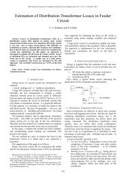
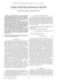
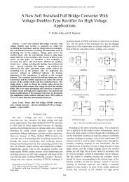
Fig. 6. <strong>Voltage</strong> across CB c<strong>on</strong>tacts in case.2.<br />
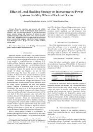
Case.3: Simulati<strong>on</strong> <str<strong>on</strong>g>of</str<strong>on</strong>g> switching and reclosing <str<strong>on</strong>g>of</str<strong>on</strong>g> C.B., in<br />
presence <str<strong>on</strong>g>of</str<strong>on</strong>g> no-load transformer:<br />
In the third scenario system is in no load operating<br />
c<strong>on</strong>diti<strong>on</strong>. Before starting the simulati<strong>on</strong> these c<strong>on</strong>diti<strong>on</strong>s are<br />
applied to the system: Transformers operate in no load<br />
c<strong>on</strong>diti<strong>on</strong> and all <str<strong>on</strong>g>of</str<strong>on</strong>g> the 132kV outgoings are disc<strong>on</strong>nected.<br />
Cables are disc<strong>on</strong>nected from 132kV busbar. <strong>Circuit</strong>-breakers<br />
“=C02-QA1, =C02-QA2, =C01-QA1, =C01-QA2 and<br />
=C01-QA3” are closed and “=C02-QA3” is opened. Tap <str<strong>on</strong>g>of</str<strong>on</strong>g><br />
the transformers are regulated <strong>on</strong> 1.05.<br />
In the moment <str<strong>on</strong>g>of</str<strong>on</strong>g> 0.999 sec<strong>on</strong>ds =C01-QA3 is opened and<br />
in the moment <str<strong>on</strong>g>of</str<strong>on</strong>g> 1.0653 sec<strong>on</strong>ds reclosed. Again in the<br />
moment <str<strong>on</strong>g>of</str<strong>on</strong>g> 2 sec<strong>on</strong>ds, the system becomes stable again.<br />
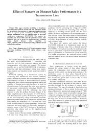
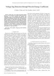
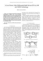
According to Fig. 7, the maximum peak over-voltage that<br />
occurs is about 428kV phase to earth equal to 1.86 times<br />
greater than normal operating phase voltage.<br />
500<br />
400<br />
300<br />
200<br />
100<br />
0<br />
-100<br />
-200<br />
-300<br />
-400<br />
-500<br />
Advanced Graph Frame<br />
CB VOLTAGE ACROSS POLES PH:C PEAK<br />
0.00 0.25 0.50 0.75 1.00 1.25 1.50 1.75 2.00 ...<br />
...<br />
...<br />
Fig. 7. <strong>Voltage</strong> across CB c<strong>on</strong>tacts in case.3<br />
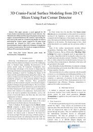
Case.4: Simulati<strong>on</strong> <str<strong>on</strong>g>of</str<strong>on</strong>g> switching, reclosing and reopening<br />
<str<strong>on</strong>g>of</str<strong>on</strong>g> C.B., in presence <str<strong>on</strong>g>of</str<strong>on</strong>g> no-load transformers and double<br />
circuit transmissi<strong>on</strong> line:<br />
In the forth scenario system is in no load operating<br />
c<strong>on</strong>diti<strong>on</strong>. Before starting the simulati<strong>on</strong> these c<strong>on</strong>diti<strong>on</strong>s are<br />
applied to the system: Transformers operate in no load<br />
c<strong>on</strong>diti<strong>on</strong> and all <str<strong>on</strong>g>of</str<strong>on</strong>g> the 132kV outgoings are disc<strong>on</strong>nected.<br />
Cables are disc<strong>on</strong>nected from 132kV busbar. <strong>Circuit</strong>-breakers<br />
“=C02-QA1, =C02-QA2, =C01-QA1 and =C01-QA2” are<br />
closed and “=C02-QA3 and =C01-QA3” are opened. Tap <str<strong>on</strong>g>of</str<strong>on</strong>g><br />
the transformers are regulated <strong>on</strong> 1.05.<br />
In the moment <str<strong>on</strong>g>of</str<strong>on</strong>g> 0.999 sec<strong>on</strong>ds =C01-QA3 is closed and in<br />
the moment <str<strong>on</strong>g>of</str<strong>on</strong>g> 1.0653 sec<strong>on</strong>ds reopened. Again in the<br />
moment <str<strong>on</strong>g>of</str<strong>on</strong>g> 2 sec<strong>on</strong>ds, the system becomes stable again.<br />
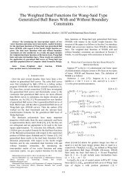
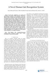
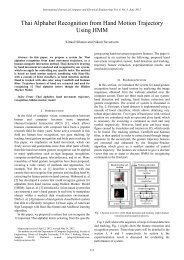
According to Fig. 8, the maximum peak over-voltage that<br />
occurs is about 710kV phase to earth equal to 3.08 times<br />
greater than normal operating phase voltage.<br />
800<br />
600<br />
400<br />
200<br />
0<br />
-200<br />
-400<br />
-600<br />
-800<br />
Advanced Graph Frame<br />
CB VOLTAGE ACROSS POLES PH:A PEAK<br />
0.00 0.25 0.50 0.75 1.00 1.25 1.50 1.75 2.00 ...<br />
...<br />
...<br />
Fig. 8. <strong>Voltage</strong> across CB c<strong>on</strong>tacts in case.4<br />
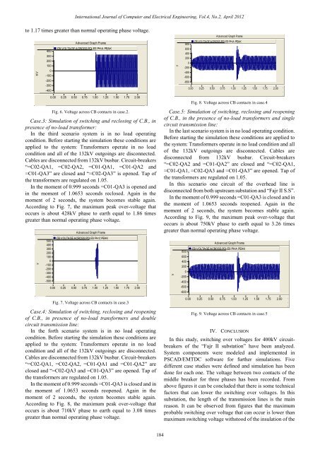
Case.5: Simulati<strong>on</strong> <str<strong>on</strong>g>of</str<strong>on</strong>g> switching, reclosing and reopening<br />
<str<strong>on</strong>g>of</str<strong>on</strong>g> C.B., in the presence <str<strong>on</strong>g>of</str<strong>on</strong>g> no-load transformers and single<br />
circuit transmissi<strong>on</strong> line:<br />
In the last scenario system is in no load operating c<strong>on</strong>diti<strong>on</strong>.<br />
Before starting the simulati<strong>on</strong> these c<strong>on</strong>diti<strong>on</strong>s are applied to<br />
the system: Transformers operate in no load c<strong>on</strong>diti<strong>on</strong> and all<br />
<str<strong>on</strong>g>of</str<strong>on</strong>g> the 132kV outgoings are disc<strong>on</strong>nected. Cables are<br />
disc<strong>on</strong>nected from 132kV busbar. <strong>Circuit</strong>-breakers<br />
“=C02-QA2 and =C01-QA2” are closed and “=C02-QA1,<br />
=C01-QA1, =C02-QA3 and =C01-QA3” are opened. Tap <str<strong>on</strong>g>of</str<strong>on</strong>g><br />
the transformers are regulated <strong>on</strong> 1.05.<br />
In this scenario <strong>on</strong>e circuit <str<strong>on</strong>g>of</str<strong>on</strong>g> the overhead line is<br />
disc<strong>on</strong>nected from both upstream substati<strong>on</strong> and “Fajr II S.S”.<br />
In the moment <str<strong>on</strong>g>of</str<strong>on</strong>g> 0.999 sec<strong>on</strong>ds =C01-QA3 is closed and in<br />
the moment <str<strong>on</strong>g>of</str<strong>on</strong>g> 1.0653 sec<strong>on</strong>ds reopened. Again in the<br />
moment <str<strong>on</strong>g>of</str<strong>on</strong>g> 2 sec<strong>on</strong>ds, the system becomes stable again.<br />
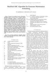
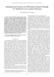
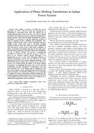
According to Fig. 9, the maximum peak over-voltage that<br />
occurs is about 750kV phase to earth equal to 3.26 times<br />
greater than normal operating phase voltage.<br />
800<br />
600<br />
400<br />
200<br />
0<br />
-200<br />
-400<br />
-600<br />
-800<br />
Advanced Graph Frame<br />
CB VOLTAGE ACROSS POLES PH:A PEAK<br />
0.00 0.25 0.50 0.75 1.00 1.25 1.50 1.75 2.00 ...<br />
...<br />
...<br />
Fig. 9. <strong>Voltage</strong> across CB c<strong>on</strong>tacts in case.5<br />
IV. CONCLUSION<br />
In this study, switching over voltages for 400kV circuitbreakers<br />
<str<strong>on</strong>g>of</str<strong>on</strong>g> the “Fajr II substati<strong>on</strong>” have been analyzed.<br />
System comp<strong>on</strong>ents were modeled and implemented in<br />
PSCAD/EMTDC s<str<strong>on</strong>g>of</str<strong>on</strong>g>tware for further simulati<strong>on</strong>s. Five<br />
different case studies were defined and simulati<strong>on</strong> has been<br />
d<strong>on</strong>e for each <strong>on</strong>e. The voltage between two c<strong>on</strong>tacts <str<strong>on</strong>g>of</str<strong>on</strong>g> the<br />
middle breaker for three phases has been recorded. From<br />
above figures it can be c<strong>on</strong>cluded that there is some technical<br />
factors that can lower the switching over voltages. In this<br />
substati<strong>on</strong>, the length <str<strong>on</strong>g>of</str<strong>on</strong>g> the transmissi<strong>on</strong> lines is the main<br />
reas<strong>on</strong>. It can be observed from figures that the maximum<br />
probable switching over voltage that can occur is lower than<br />
maximum switching voltage withstood <str<strong>on</strong>g>of</str<strong>on</strong>g> the insulati<strong>on</strong> <str<strong>on</strong>g>of</str<strong>on</strong>g> the<br />
184