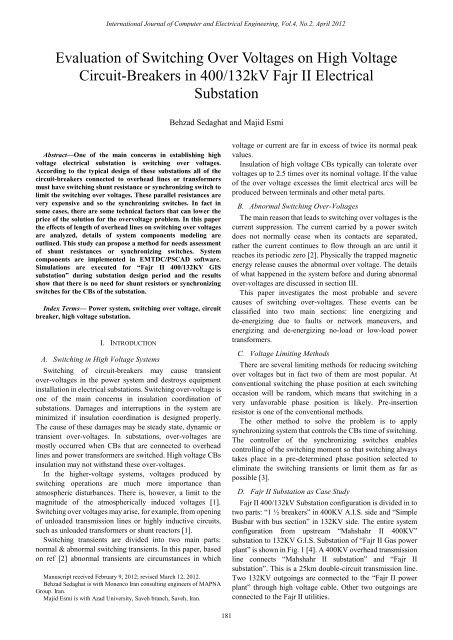
Evaluation of Switching Over Voltages on High Voltage Circuit - ijcee
Evaluation of Switching Over Voltages on High Voltage Circuit - ijcee
Evaluation of Switching Over Voltages on High Voltage Circuit - ijcee

Create successful ePaper yourself
Turn your PDF publications into a flip-book with our unique Google optimized e-Paper software.
Internati<strong>on</strong>al Journal <str<strong>on</strong>g>of</str<strong>on</strong>g> Computer and Electrical Engineering, Vol.4, No.2, April 2012<br />
<str<strong>on</strong>g>Evaluati<strong>on</strong></str<strong>on</strong>g> <str<strong>on</strong>g>of</str<strong>on</strong>g> <str<strong>on</strong>g>Switching</str<strong>on</strong>g> <str<strong>on</strong>g>Over</str<strong>on</strong>g> <str<strong>on</strong>g><strong>Voltage</strong>s</str<strong>on</strong>g> <strong>on</strong> <strong>High</strong> <strong>Voltage</strong><br />
<strong>Circuit</strong>-Breakers in 400/132kV Fajr II Electrical<br />
Substati<strong>on</strong><br />
Behzad Sedaghat and Majid Esmi<br />
<br />
Abstract—One <str<strong>on</strong>g>of</str<strong>on</strong>g> the main c<strong>on</strong>cerns in establishing high<br />
voltage electrical substati<strong>on</strong> is switching over voltages.<br />
According to the typical design <str<strong>on</strong>g>of</str<strong>on</strong>g> these substati<strong>on</strong>s all <str<strong>on</strong>g>of</str<strong>on</strong>g> the<br />
circuit-breakers c<strong>on</strong>nected to overhead lines or transformers<br />
must have switching shunt resistance or synchr<strong>on</strong>izing switch to<br />
limit the switching over voltages. These parallel resistances are<br />
very expensive and so the synchr<strong>on</strong>izing switches. In fact in<br />
some cases, there are some technical factors that can lower the<br />
price <str<strong>on</strong>g>of</str<strong>on</strong>g> the soluti<strong>on</strong> for the overvoltage problem. In this paper<br />
the effects <str<strong>on</strong>g>of</str<strong>on</strong>g> length <str<strong>on</strong>g>of</str<strong>on</strong>g> overhead lines <strong>on</strong> switching over voltages<br />
are analyzed, details <str<strong>on</strong>g>of</str<strong>on</strong>g> system comp<strong>on</strong>ents modeling are<br />
outlined. This study can propose a method for needs assessment<br />
<str<strong>on</strong>g>of</str<strong>on</strong>g> shunt resistances or synchr<strong>on</strong>izing switches. System<br />
comp<strong>on</strong>ents are implemented in EMTDC/PSCAD s<str<strong>on</strong>g>of</str<strong>on</strong>g>tware.<br />
Simulati<strong>on</strong>s are executed for “Fajr II 400/132KV GIS<br />
substati<strong>on</strong>” during substati<strong>on</strong> design period and the results<br />
show that there is no need for shunt resistors or synchr<strong>on</strong>izing<br />
switches for the CBs <str<strong>on</strong>g>of</str<strong>on</strong>g> the substati<strong>on</strong>.<br />
Index Terms— Power system, switching over voltage, circuit<br />
breaker, high voltage substati<strong>on</strong>.<br />
I. INTRODUCTION<br />
A. <str<strong>on</strong>g>Switching</str<strong>on</strong>g> in <strong>High</strong> <strong>Voltage</strong> Systems<br />
<str<strong>on</strong>g>Switching</str<strong>on</strong>g> <str<strong>on</strong>g>of</str<strong>on</strong>g> circuit-breakers may cause transient<br />
over-voltages in the power system and destroys equipment<br />
installati<strong>on</strong> in electrical substati<strong>on</strong>s. <str<strong>on</strong>g>Switching</str<strong>on</strong>g> over-voltage is<br />
<strong>on</strong>e <str<strong>on</strong>g>of</str<strong>on</strong>g> the main c<strong>on</strong>cerns in insulati<strong>on</strong> coordinati<strong>on</strong> <str<strong>on</strong>g>of</str<strong>on</strong>g><br />
substati<strong>on</strong>s. Damages and interrupti<strong>on</strong>s in the system are<br />
minimized if insulati<strong>on</strong> coordinati<strong>on</strong> is designed properly.<br />
The cause <str<strong>on</strong>g>of</str<strong>on</strong>g> these damages may be steady state, dynamic or<br />
transient over-voltages. In substati<strong>on</strong>s, over-voltages are<br />
mostly occurred when CBs that are c<strong>on</strong>nected to overhead<br />
lines and power transformers are switched. <strong>High</strong> voltage CBs<br />
insulati<strong>on</strong> may not withstand these over-voltages.<br />
In the higher-voltage systems, voltages produced by<br />
switching operati<strong>on</strong>s are much more importance than<br />
atmospheric disturbances. There is, however, a limit to the<br />
magnitude <str<strong>on</strong>g>of</str<strong>on</strong>g> the atmospherically induced voltages [1].<br />
<str<strong>on</strong>g>Switching</str<strong>on</strong>g> over voltages may arise, for example, from opening<br />
<str<strong>on</strong>g>of</str<strong>on</strong>g> unloaded transmissi<strong>on</strong> lines or highly inductive circuits,<br />
such as unloaded transformers or shunt reactors [1].<br />
<str<strong>on</strong>g>Switching</str<strong>on</strong>g> transients are divided into two main parts:<br />
normal & abnormal switching transients. In this paper, based<br />
<strong>on</strong> ref [2] abnormal transients are circumstances in which<br />
Manuscript received February 9, 2012; revised March 12, 2012.<br />
Behzad Sedaghat is with M<strong>on</strong>enco Iran c<strong>on</strong>sulting engineers <str<strong>on</strong>g>of</str<strong>on</strong>g> MAPNA<br />
Group. Iran.<br />
Majid Esmi is with Azad University, Saveh branch, Saveh, Iran.<br />
voltage or current are far in excess <str<strong>on</strong>g>of</str<strong>on</strong>g> twice its normal peak<br />
values.<br />
Insulati<strong>on</strong> <str<strong>on</strong>g>of</str<strong>on</strong>g> high voltage CBs typically can tolerate over<br />
voltages up to 2.5 times over its nominal voltage. If the value<br />
<str<strong>on</strong>g>of</str<strong>on</strong>g> the over voltage excesses the limit electrical arcs will be<br />
produced between terminals and other metal parts.<br />
B. Abnormal <str<strong>on</strong>g>Switching</str<strong>on</strong>g> <str<strong>on</strong>g>Over</str<strong>on</strong>g>-<str<strong>on</strong>g><strong>Voltage</strong>s</str<strong>on</strong>g><br />
The main reas<strong>on</strong> that leads to switching over voltages is the<br />
current suppressi<strong>on</strong>. The current carried by a power switch<br />
does not normally cease when its c<strong>on</strong>tacts are separated,<br />
rather the current c<strong>on</strong>tinues to flow through an arc until it<br />
reaches its periodic zero [2]. Physically the trapped magnetic<br />
energy release causes the abnormal over voltage. The details<br />
<str<strong>on</strong>g>of</str<strong>on</strong>g> what happened in the system before and during abnormal<br />
over-voltages are discussed in secti<strong>on</strong> III.<br />
This paper investigates the most probable and severe<br />
causes <str<strong>on</strong>g>of</str<strong>on</strong>g> switching over-voltages. These events can be<br />
classified into two main secti<strong>on</strong>s: line energizing and<br />
de-energizing due to faults or network maneuvers, and<br />
energizing and de-energizing no-load or low-load power<br />
transformers.<br />
C. <strong>Voltage</strong> Limiting Methods<br />
There are several limiting methods for reducing switching<br />
over voltages but in fact two <str<strong>on</strong>g>of</str<strong>on</strong>g> them are most popular. At<br />
c<strong>on</strong>venti<strong>on</strong>al switching the phase positi<strong>on</strong> at each switching<br />
occasi<strong>on</strong> will be random, which means that switching in a<br />
very unfavorable phase positi<strong>on</strong> is likely. Pre-inserti<strong>on</strong><br />
resistor is <strong>on</strong>e <str<strong>on</strong>g>of</str<strong>on</strong>g> the c<strong>on</strong>venti<strong>on</strong>al methods.<br />
The other method to solve the problem is to apply<br />
synchr<strong>on</strong>izing system that c<strong>on</strong>trols the CBs time <str<strong>on</strong>g>of</str<strong>on</strong>g> switching.<br />
The c<strong>on</strong>troller <str<strong>on</strong>g>of</str<strong>on</strong>g> the synchr<strong>on</strong>izing switches enables<br />
c<strong>on</strong>trolling <str<strong>on</strong>g>of</str<strong>on</strong>g> the switching moment so that switching always<br />
takes place in a pre-determined phase positi<strong>on</strong> selected to<br />
eliminate the switching transients or limit them as far as<br />
possible [3].<br />
D. Fajr II Substati<strong>on</strong> as Case Study<br />
Fajr II 400/132kV Substati<strong>on</strong> c<strong>on</strong>figurati<strong>on</strong> is divided in to<br />
two parts: “1 ½ breakers” in 400KV A.I.S. side and “Simple<br />
Busbar with bus secti<strong>on</strong>” in 132KV side. The entire system<br />
c<strong>on</strong>figurati<strong>on</strong> from upstream “Mahshahr II 400KV”<br />
substati<strong>on</strong> to 132KV G.I.S. Substati<strong>on</strong> <str<strong>on</strong>g>of</str<strong>on</strong>g> “Fajr II Gas power<br />
plant” is shown in Fig. 1 [4]. A 400KV overhead transmissi<strong>on</strong><br />
line c<strong>on</strong>nects “Mahshahr II substati<strong>on</strong>” and “Fajr II<br />
substati<strong>on</strong>”. This is a 25km double-circuit transmissi<strong>on</strong> line.<br />
Two 132KV outgoings are c<strong>on</strong>nected to the “Fajr II power<br />
plant” through high voltage cable. Other two outgoings are<br />
c<strong>on</strong>nected to the Fajr II utilities.<br />
181
Internati<strong>on</strong>al Journal <str<strong>on</strong>g>of</str<strong>on</strong>g> Computer and Electrical Engineering, Vol.4, No.2, April 2012<br />
II. SYSTEM COMPONENTS<br />
This secti<strong>on</strong> includes a brief descripti<strong>on</strong> <str<strong>on</strong>g>of</str<strong>on</strong>g> the system<br />
comp<strong>on</strong>ents, modeling and implementati<strong>on</strong> <str<strong>on</strong>g>of</str<strong>on</strong>g> these<br />
comp<strong>on</strong>ents in PSCAD/EMTDC s<str<strong>on</strong>g>of</str<strong>on</strong>g>tware. In this study,<br />
switching <strong>on</strong> no-load transformer and 400KV transmissi<strong>on</strong><br />
line are analyzed. For simplificati<strong>on</strong> “Mahshahr II S.S” is<br />
assumed as an infinite bus and “Fajr II power plant” is<br />
assumed as a simple voltage sources with internal resistor.<br />
Detailed modeling <str<strong>on</strong>g>of</str<strong>on</strong>g> the basic comp<strong>on</strong>ents can be found in<br />
[5].<br />
15 [m]<br />
C2<br />
.4572 [m]<br />
Fig. 1. System C<strong>on</strong>figurati<strong>on</strong>.<br />
C3<br />
C1<br />
G1<br />
C6<br />
10 [m]<br />
16.4 [m]<br />
Tower: T2K15<br />
27 [m]<br />
C<strong>on</strong>ductors: curlew<br />
Ground_Wires: Curlew Core<br />
0 [m]<br />
G2<br />
0.6<br />
C4<br />
Ground Resistivity: 50 [ohm*m]<br />
Relative Ground Permeability: 1.0<br />
Earth Return Formula: Deri-Semlyen<br />
C5<br />
Fig. 2. Transmissi<strong>on</strong> line c<strong>on</strong>figurati<strong>on</strong><br />
A. 400kV Transmissi<strong>on</strong> Lines<br />
8.8 [m]<br />
Modeling <str<strong>on</strong>g>of</str<strong>on</strong>g> transmissi<strong>on</strong> lines in a network requires<br />
dimensi<strong>on</strong>s and technical data. The transmissi<strong>on</strong> line data<br />
includes: transmissi<strong>on</strong> line c<strong>on</strong>ductor diameter and resistance<br />
per unit length <str<strong>on</strong>g>of</str<strong>on</strong>g> transmissi<strong>on</strong> line, phase transformati<strong>on</strong> data<br />
and distance between phase bundle, spacing between phases,<br />
shield wire diameter and resistance per unit length, height <str<strong>on</strong>g>of</str<strong>on</strong>g><br />
each c<strong>on</strong>ductor and shield wire at the tower and sag to<br />
midspan, tower dimensi<strong>on</strong>s, and ground c<strong>on</strong>ductivity [5]. For<br />
this case study the technical data for double circuit<br />
transmissi<strong>on</strong> line between “Mahshahr S.S” and “Fajr II S.S”<br />
can be found in [4].<br />
With reference to the PSCAD/EMTDC, Berger<strong>on</strong> line<br />
model is selected. Transmissi<strong>on</strong> line model is transposed<br />
frequency dependent phase model based <strong>on</strong> travelling time<br />
and characteristic impedance <str<strong>on</strong>g>of</str<strong>on</strong>g> the line. The transmissi<strong>on</strong><br />
line detail modeling for electromagnetic transient studies can<br />
be found in [6].<br />
The 25 km double circuit transmissi<strong>on</strong> line is arranged<br />
according to Fig. 2. Type <str<strong>on</strong>g>of</str<strong>on</strong>g> the tower is T2K15 with double<br />
bundled Curlew as main c<strong>on</strong>ductor and Curlew core as shield<br />
c<strong>on</strong>ductor.<br />
B. 400/132KV Power Transformer<br />
Transformer models are represented with several technical<br />
data: MVA rating, wingding c<strong>on</strong>figurati<strong>on</strong> and voltage, tap<br />
change range and normal setting, leakage reactance between<br />
windings, knee point <str<strong>on</strong>g>of</str<strong>on</strong>g> transformer core saturati<strong>on</strong><br />
characteristic in per unit <str<strong>on</strong>g>of</str<strong>on</strong>g> rate flux or voltage, and estimated<br />
saturated air core reactance [5]. The transformer detail<br />
modeling for transient studies can be found in [7] and [8].<br />
The 315 MVA, 400/132kV, transformers are represented<br />
by saturable transformer models with two H.V. windings. The<br />
saturati<strong>on</strong> characteristics <str<strong>on</strong>g>of</str<strong>on</strong>g> these transformers are determined.<br />
The parameters <str<strong>on</strong>g>of</str<strong>on</strong>g> the pre-modeled transformer block in the<br />
s<str<strong>on</strong>g>of</str<strong>on</strong>g>tware are adjusted based <strong>on</strong> manufacturer’s technical<br />
specificati<strong>on</strong>. The technical specificati<strong>on</strong> data can be found in<br />
[4].<br />
C. Infinite Bus<br />
Infinite bus can be described as an ideal 3 phase voltage<br />
source with a internal resistance according to network<br />
Thevenin’s theorem impedance from the “Mahshahr S.S.”<br />
System data can be found in [4].<br />
D. <strong>Circuit</strong>-Breaker<br />
In this study, breakers are classified as simple switch<br />
models, which change branch resistance between two given<br />
values. They are c<strong>on</strong>trolled through an input c<strong>on</strong>trol signal.<br />
The ON and OFF resistances themselves cannot be<br />
changed dynamically during the run [9]. <strong>High</strong>ly n<strong>on</strong>-linear arc<br />
characteristics, which can occur in actual breakers, are not<br />
modeled in these comp<strong>on</strong>ents.<br />
In this substati<strong>on</strong>, the insulati<strong>on</strong> creepage <str<strong>on</strong>g>of</str<strong>on</strong>g> the<br />
circuit-breaker can withstand switching over voltages up to<br />
1050kV (Fig .3). Much other circuit breaker informati<strong>on</strong> can<br />
be found in [4].<br />
Fig. 3. 400kV <strong>Circuit</strong>-breakers installed in “FajrII S.S”<br />
III. RESULT AND DISCUSSION<br />
Actually, thirteen different switching scenarios have been<br />
182
y<br />
Internati<strong>on</strong>al Journal <str<strong>on</strong>g>of</str<strong>on</strong>g> Computer and Electrical Engineering, Vol.4, No.2, April 2012<br />
c<strong>on</strong>sidered and analyzed in [4]. These scenarios include<br />
different states <str<strong>on</strong>g>of</str<strong>on</strong>g> switching c<strong>on</strong>diti<strong>on</strong>s like existence or<br />
absence <str<strong>on</strong>g>of</str<strong>on</strong>g> short-circuit, re-closing, re-opening, no load<br />
transformer and etc. In this paper <strong>on</strong>ly five scenarios are<br />
presented. These are the main cases and other eight c<strong>on</strong>diti<strong>on</strong>s<br />
are split from these five.<br />
A. Theory <str<strong>on</strong>g>of</str<strong>on</strong>g> <str<strong>on</strong>g>Switching</str<strong>on</strong>g> <str<strong>on</strong>g>Over</str<strong>on</strong>g>-<str<strong>on</strong>g><strong>Voltage</strong>s</str<strong>on</strong>g><br />
The main factor that causes the switching abnormal over<br />
voltage is release <str<strong>on</strong>g>of</str<strong>on</strong>g> trapped magnetic energy. It is supposed<br />
that at the time the current chopping occurs the instantaneous<br />
current is I0. It flows in the transformer winding and is<br />
associated with a certain amount <str<strong>on</strong>g>of</str<strong>on</strong>g> magnetic energy (Eq. 1)<br />
[2].<br />
1 2<br />
Energy L I<br />
(1)<br />
m 0<br />
2<br />
where, L m is magnetizing inductance.<br />
Because <str<strong>on</strong>g>of</str<strong>on</strong>g> value <str<strong>on</strong>g>of</str<strong>on</strong>g> L m is very large, the current cannot<br />
cease suddenly in such an inductive circuit [2]. The current is<br />
diverted into the capacitance <str<strong>on</strong>g>of</str<strong>on</strong>g> the transformer winding and<br />
capacitance <str<strong>on</strong>g>of</str<strong>on</strong>g> the c<strong>on</strong>necti<strong>on</strong> between switch and<br />
transformer. The energy from the magnetic field <str<strong>on</strong>g>of</str<strong>on</strong>g> the<br />
transformer is transferred to the electric field <str<strong>on</strong>g>of</str<strong>on</strong>g> the<br />
capacitance.<br />
The peak voltage reached across the capacitor and<br />
therefore across the winding, is given by (2).<br />
V p<br />
I 0<br />
Z 0<br />
(2)<br />
where, Z 0 is the system surge impedance and can be calculated<br />
using (3), and V p is the over voltage peak value.<br />
Z<br />
0<br />
<br />
Lm<br />
C<br />
where, C is the effective capacitance. The effective<br />
capacitance will vary depending <strong>on</strong> the type <str<strong>on</strong>g>of</str<strong>on</strong>g> winding and<br />
the insulati<strong>on</strong>.<br />
It can be c<strong>on</strong>cluded from (2) and (3) that the transient<br />
voltage is independent <str<strong>on</strong>g>of</str<strong>on</strong>g> the system voltage. In fact, the<br />
over-voltage value would not reach nearly as high as the value<br />
obtained from the (2). Losses are <strong>on</strong>e reas<strong>on</strong> causing the<br />
damping, but more important reas<strong>on</strong> is that <strong>on</strong>ly a fracti<strong>on</strong> <str<strong>on</strong>g>of</str<strong>on</strong>g><br />
the energy trapped in the core at the time <str<strong>on</strong>g>of</str<strong>on</strong>g> chop is released<br />
[2] (Fig. 4).<br />
Fig. 4. Energy released by a transformer core when the magnetizing current<br />
is chopped<br />
Practically in the worst case, chopping current at the peak,<br />
the chopping voltage will not exceed 55% <str<strong>on</strong>g>of</str<strong>on</strong>g> what calculated<br />
(3)<br />
before. Based <strong>on</strong> this fact, switching voltage can be obtained<br />
from (4) [2].<br />
v<br />
( s)<br />
<br />
s<br />
2<br />
sV(0)<br />
s 1<br />
<br />
RC L C<br />
<br />
C [<br />
s<br />
2<br />
m<br />
V(0)<br />
<br />
RC<br />
s<br />
I0<br />
s 1<br />
]<br />
RC L C<br />
B. Simulati<strong>on</strong> and Results<br />
m<br />
2<br />
1<br />
s 1<br />
<br />
RC L C<br />
In this secti<strong>on</strong> five scenarios that lead to switching<br />
over-voltage are presented. It should be c<strong>on</strong>sidered that <strong>on</strong>ly<br />
the worst phase will be presented in each case. According to<br />
simulati<strong>on</strong> the worst cases are happened for middle circuit<br />
breaker in each “1 ½ breaker” switchgear bay.<br />
Case.1: Simulati<strong>on</strong> <str<strong>on</strong>g>of</str<strong>on</strong>g> <str<strong>on</strong>g>Switching</str<strong>on</strong>g> <str<strong>on</strong>g>of</str<strong>on</strong>g> C.B., During Normal<br />
Operati<strong>on</strong>:<br />
In the first scenario system is in a stable operating<br />
c<strong>on</strong>diti<strong>on</strong>. Before starting the simulati<strong>on</strong> these c<strong>on</strong>diti<strong>on</strong>s are<br />
applied to the system: 400kV transmissi<strong>on</strong> line is c<strong>on</strong>nected<br />
to system. <strong>Circuit</strong>-breakers “=C01-QA1, =C02-QA1,<br />
=C01-QA2 and =C02-QA2” are closed and “=C01-QA3 and<br />
=C02-QA3” are opened. Tap <str<strong>on</strong>g>of</str<strong>on</strong>g> the transformers are<br />
regulated <strong>on</strong> 1.05. 132kV load outgoings are c<strong>on</strong>nected and<br />
Fajr power plant feeders are disc<strong>on</strong>nected from the system.<br />
In the moment <str<strong>on</strong>g>of</str<strong>on</strong>g> 1 sec<strong>on</strong>d =C01-QA3 is closed and after<br />
0.1 sec<strong>on</strong>ds reopened. Again after about 0.9 sec<strong>on</strong>ds, by<br />
closing C.B. –QA3 the system becomes stable again.<br />
According to Fig. 5, there is a little over-voltage in phase c.<br />
400<br />
300<br />
200<br />
100<br />
0<br />
-100<br />
-200<br />
-300<br />
-400<br />
Advanced Graph Frame<br />
CB VOLTAGE ACROSS POLES PH:C PEAK<br />
0.00 0.25 0.50 0.75 1.00 1.25 1.50 1.75 2.00 ...<br />
...<br />
...<br />
Fig. 5. <strong>Voltage</strong> across CB c<strong>on</strong>tacts in case.1<br />
Case.2: Simulati<strong>on</strong> <str<strong>on</strong>g>of</str<strong>on</strong>g> switching <str<strong>on</strong>g>of</str<strong>on</strong>g> C.B., during<br />
short-circuit:<br />
In the sec<strong>on</strong>d scenario system is in a stable operating<br />
c<strong>on</strong>diti<strong>on</strong>. Before starting the simulati<strong>on</strong> these c<strong>on</strong>diti<strong>on</strong>s are<br />
applied to the system: 400kV transmissi<strong>on</strong> line is c<strong>on</strong>nected<br />
to system. <strong>Circuit</strong>-breakers “=C02-QA1, =C02-QA2,<br />
=C02-QA3 and =C03-QA3” are closed and “=C01-QA1 and<br />
=C01-QA2” are opened. Tap <str<strong>on</strong>g>of</str<strong>on</strong>g> the transformers are<br />
regulated <strong>on</strong> 1.05. 132kV outgoing feeders are c<strong>on</strong>nected and<br />
“Fajr II power plant” feeders also are c<strong>on</strong>nected to the system.<br />
Three phase short-circuit is occurred at the end <str<strong>on</strong>g>of</str<strong>on</strong>g> the<br />
Cable1. After 0.1 sec<strong>on</strong>ds =C01-QA3 and =E5-QA1 are<br />
tripped and opened. In the moment <str<strong>on</strong>g>of</str<strong>on</strong>g> 1.4 sec<strong>on</strong>ds fault is<br />
cleared. Again after about 0.6 sec<strong>on</strong>ds, the system becomes<br />
stable again. According to Fig. 6, the maximum peak<br />
over-voltage that occurs is about 370kV phase to earth equal<br />
m<br />
(4)<br />
183
y<br />
y<br />
KV<br />
y<br />
Internati<strong>on</strong>al Journal <str<strong>on</strong>g>of</str<strong>on</strong>g> Computer and Electrical Engineering, Vol.4, No.2, April 2012<br />
to 1.17 times greater than normal operating phase voltage.<br />
400<br />
300<br />
200<br />
100<br />
0<br />
-100<br />
-200<br />
-300<br />
-400<br />
Advanced Graph Frame<br />
CB VOLTAGE ACROSS POLES PH:A PEAK<br />
0.00 0.25 0.50 0.75 1.00 1.25 1.50 1.75 2.00 ...<br />
...<br />
...<br />
Fig. 6. <strong>Voltage</strong> across CB c<strong>on</strong>tacts in case.2.<br />
Case.3: Simulati<strong>on</strong> <str<strong>on</strong>g>of</str<strong>on</strong>g> switching and reclosing <str<strong>on</strong>g>of</str<strong>on</strong>g> C.B., in<br />
presence <str<strong>on</strong>g>of</str<strong>on</strong>g> no-load transformer:<br />
In the third scenario system is in no load operating<br />
c<strong>on</strong>diti<strong>on</strong>. Before starting the simulati<strong>on</strong> these c<strong>on</strong>diti<strong>on</strong>s are<br />
applied to the system: Transformers operate in no load<br />
c<strong>on</strong>diti<strong>on</strong> and all <str<strong>on</strong>g>of</str<strong>on</strong>g> the 132kV outgoings are disc<strong>on</strong>nected.<br />
Cables are disc<strong>on</strong>nected from 132kV busbar. <strong>Circuit</strong>-breakers<br />
“=C02-QA1, =C02-QA2, =C01-QA1, =C01-QA2 and<br />
=C01-QA3” are closed and “=C02-QA3” is opened. Tap <str<strong>on</strong>g>of</str<strong>on</strong>g><br />
the transformers are regulated <strong>on</strong> 1.05.<br />
In the moment <str<strong>on</strong>g>of</str<strong>on</strong>g> 0.999 sec<strong>on</strong>ds =C01-QA3 is opened and<br />
in the moment <str<strong>on</strong>g>of</str<strong>on</strong>g> 1.0653 sec<strong>on</strong>ds reclosed. Again in the<br />
moment <str<strong>on</strong>g>of</str<strong>on</strong>g> 2 sec<strong>on</strong>ds, the system becomes stable again.<br />
According to Fig. 7, the maximum peak over-voltage that<br />
occurs is about 428kV phase to earth equal to 1.86 times<br />
greater than normal operating phase voltage.<br />
500<br />
400<br />
300<br />
200<br />
100<br />
0<br />
-100<br />
-200<br />
-300<br />
-400<br />
-500<br />
Advanced Graph Frame<br />
CB VOLTAGE ACROSS POLES PH:C PEAK<br />
0.00 0.25 0.50 0.75 1.00 1.25 1.50 1.75 2.00 ...<br />
...<br />
...<br />
Fig. 7. <strong>Voltage</strong> across CB c<strong>on</strong>tacts in case.3<br />
Case.4: Simulati<strong>on</strong> <str<strong>on</strong>g>of</str<strong>on</strong>g> switching, reclosing and reopening<br />
<str<strong>on</strong>g>of</str<strong>on</strong>g> C.B., in presence <str<strong>on</strong>g>of</str<strong>on</strong>g> no-load transformers and double<br />
circuit transmissi<strong>on</strong> line:<br />
In the forth scenario system is in no load operating<br />
c<strong>on</strong>diti<strong>on</strong>. Before starting the simulati<strong>on</strong> these c<strong>on</strong>diti<strong>on</strong>s are<br />
applied to the system: Transformers operate in no load<br />
c<strong>on</strong>diti<strong>on</strong> and all <str<strong>on</strong>g>of</str<strong>on</strong>g> the 132kV outgoings are disc<strong>on</strong>nected.<br />
Cables are disc<strong>on</strong>nected from 132kV busbar. <strong>Circuit</strong>-breakers<br />
“=C02-QA1, =C02-QA2, =C01-QA1 and =C01-QA2” are<br />
closed and “=C02-QA3 and =C01-QA3” are opened. Tap <str<strong>on</strong>g>of</str<strong>on</strong>g><br />
the transformers are regulated <strong>on</strong> 1.05.<br />
In the moment <str<strong>on</strong>g>of</str<strong>on</strong>g> 0.999 sec<strong>on</strong>ds =C01-QA3 is closed and in<br />
the moment <str<strong>on</strong>g>of</str<strong>on</strong>g> 1.0653 sec<strong>on</strong>ds reopened. Again in the<br />
moment <str<strong>on</strong>g>of</str<strong>on</strong>g> 2 sec<strong>on</strong>ds, the system becomes stable again.<br />
According to Fig. 8, the maximum peak over-voltage that<br />
occurs is about 710kV phase to earth equal to 3.08 times<br />
greater than normal operating phase voltage.<br />
800<br />
600<br />
400<br />
200<br />
0<br />
-200<br />
-400<br />
-600<br />
-800<br />
Advanced Graph Frame<br />
CB VOLTAGE ACROSS POLES PH:A PEAK<br />
0.00 0.25 0.50 0.75 1.00 1.25 1.50 1.75 2.00 ...<br />
...<br />
...<br />
Fig. 8. <strong>Voltage</strong> across CB c<strong>on</strong>tacts in case.4<br />
Case.5: Simulati<strong>on</strong> <str<strong>on</strong>g>of</str<strong>on</strong>g> switching, reclosing and reopening<br />
<str<strong>on</strong>g>of</str<strong>on</strong>g> C.B., in the presence <str<strong>on</strong>g>of</str<strong>on</strong>g> no-load transformers and single<br />
circuit transmissi<strong>on</strong> line:<br />
In the last scenario system is in no load operating c<strong>on</strong>diti<strong>on</strong>.<br />
Before starting the simulati<strong>on</strong> these c<strong>on</strong>diti<strong>on</strong>s are applied to<br />
the system: Transformers operate in no load c<strong>on</strong>diti<strong>on</strong> and all<br />
<str<strong>on</strong>g>of</str<strong>on</strong>g> the 132kV outgoings are disc<strong>on</strong>nected. Cables are<br />
disc<strong>on</strong>nected from 132kV busbar. <strong>Circuit</strong>-breakers<br />
“=C02-QA2 and =C01-QA2” are closed and “=C02-QA1,<br />
=C01-QA1, =C02-QA3 and =C01-QA3” are opened. Tap <str<strong>on</strong>g>of</str<strong>on</strong>g><br />
the transformers are regulated <strong>on</strong> 1.05.<br />
In this scenario <strong>on</strong>e circuit <str<strong>on</strong>g>of</str<strong>on</strong>g> the overhead line is<br />
disc<strong>on</strong>nected from both upstream substati<strong>on</strong> and “Fajr II S.S”.<br />
In the moment <str<strong>on</strong>g>of</str<strong>on</strong>g> 0.999 sec<strong>on</strong>ds =C01-QA3 is closed and in<br />
the moment <str<strong>on</strong>g>of</str<strong>on</strong>g> 1.0653 sec<strong>on</strong>ds reopened. Again in the<br />
moment <str<strong>on</strong>g>of</str<strong>on</strong>g> 2 sec<strong>on</strong>ds, the system becomes stable again.<br />
According to Fig. 9, the maximum peak over-voltage that<br />
occurs is about 750kV phase to earth equal to 3.26 times<br />
greater than normal operating phase voltage.<br />
800<br />
600<br />
400<br />
200<br />
0<br />
-200<br />
-400<br />
-600<br />
-800<br />
Advanced Graph Frame<br />
CB VOLTAGE ACROSS POLES PH:A PEAK<br />
0.00 0.25 0.50 0.75 1.00 1.25 1.50 1.75 2.00 ...<br />
...<br />
...<br />
Fig. 9. <strong>Voltage</strong> across CB c<strong>on</strong>tacts in case.5<br />
IV. CONCLUSION<br />
In this study, switching over voltages for 400kV circuitbreakers<br />
<str<strong>on</strong>g>of</str<strong>on</strong>g> the “Fajr II substati<strong>on</strong>” have been analyzed.<br />
System comp<strong>on</strong>ents were modeled and implemented in<br />
PSCAD/EMTDC s<str<strong>on</strong>g>of</str<strong>on</strong>g>tware for further simulati<strong>on</strong>s. Five<br />
different case studies were defined and simulati<strong>on</strong> has been<br />
d<strong>on</strong>e for each <strong>on</strong>e. The voltage between two c<strong>on</strong>tacts <str<strong>on</strong>g>of</str<strong>on</strong>g> the<br />
middle breaker for three phases has been recorded. From<br />
above figures it can be c<strong>on</strong>cluded that there is some technical<br />
factors that can lower the switching over voltages. In this<br />
substati<strong>on</strong>, the length <str<strong>on</strong>g>of</str<strong>on</strong>g> the transmissi<strong>on</strong> lines is the main<br />
reas<strong>on</strong>. It can be observed from figures that the maximum<br />
probable switching over voltage that can occur is lower than<br />
maximum switching voltage withstood <str<strong>on</strong>g>of</str<strong>on</strong>g> the insulati<strong>on</strong> <str<strong>on</strong>g>of</str<strong>on</strong>g> the<br />
184
Internati<strong>on</strong>al Journal <str<strong>on</strong>g>of</str<strong>on</strong>g> Computer and Electrical Engineering, Vol.4, No.2, April 2012<br />
circuit breaker. Based <strong>on</strong> this c<strong>on</strong>clusi<strong>on</strong>, there is no need for<br />
expensive shunt resistor or synchr<strong>on</strong>izing switch for the<br />
400kV circuit-breakers in the “Fajr II 400/132kV substati<strong>on</strong>”.<br />
ACKNOWLEDGMENT<br />
The first author thanks Pr<str<strong>on</strong>g>of</str<strong>on</strong>g>. Rahimi for her valuable<br />
comments. The first author also thanks his wife, for her<br />
kindness during preparati<strong>on</strong> <str<strong>on</strong>g>of</str<strong>on</strong>g> the paper.<br />
REFERENCES<br />
[1] A. F. B. Young, “Some Researches <strong>on</strong> Current Chopping in<br />
<strong>High</strong>-<strong>Voltage</strong> <strong>Circuit</strong>-Breaker,” in Proc. <str<strong>on</strong>g>of</str<strong>on</strong>g> IEE, Part II: Power<br />
Engineering, August 1953.<br />
[2] A. Greenwood, Electrical Transients in Power Systems, 2rd ed. John<br />
Wiley & S<strong>on</strong>s Inc, 1991, pp.93–97.<br />
[3] ABB Product informati<strong>on</strong>, 5409 722-101 en Rev.3, SWITCHSYNC<br />
F236, ABB Power Technologies AB, Dec 2005.<br />
[4] B. Sedaghat and M. Esmi, <str<strong>on</strong>g>Switching</str<strong>on</strong>g> over-voltage analysis for FajrII<br />
400/132KV GIS S.S Report, Published <strong>on</strong>ly for client, Fajr<br />
Petrochemical Company, October 2009.<br />
[5] Introducti<strong>on</strong> to PSCAD/EMTDC V4.1, Manitoba HVDC Research<br />
Center, Winnipeg, Canada, 2003.<br />
[6] J. R. Marti, “Accurate Modeling <str<strong>on</strong>g>of</str<strong>on</strong>g> Frequency Dependent<br />
Transmissi<strong>on</strong> Lines in Electromagnetic Transient Simulati<strong>on</strong>s,” IEEE<br />
Transacti<strong>on</strong>s <strong>on</strong> Power Apparatus and Aystems, PAS-101, Jan 1982.<br />
[7] V. Brandwajn, H. W. Dommel, and I. I. Dommel, “Matrix<br />
Representati<strong>on</strong> <str<strong>on</strong>g>of</str<strong>on</strong>g> Three-Phase N-Winding Transformers for<br />
Stead-State and Transient Studies,” IEEE Transacti<strong>on</strong>s <strong>on</strong> Power<br />
Apparatus and Systems, PAS-101, June 1982.<br />
[8] F. Le<strong>on</strong> and A. Semlyen, “Complete Transformer Model for<br />
Electromagnetic Transients,” IEEE Transacti<strong>on</strong>s <strong>on</strong> Power Delivery,<br />
Vol.9, No.1, Jan 1994.<br />
[9] PSCAD/EMTDC Power System Simulati<strong>on</strong> S<str<strong>on</strong>g>of</str<strong>on</strong>g>tware User's Manual,<br />
Manitoba HVDC Research Center, Winnipeg, Canada, 1996.<br />
Behzad Sedaghat was born in 1982 in Tehran, Iran.<br />
He received his B.Sc degree in power & energy<br />
engineering from Tehran Polytechnic University,<br />
Tehran, Iran in 2007 and his M.Sc in renewable<br />
energy engineering from Zanjan University, Zanjan,<br />
in 2010.<br />
He has three years experience in power & energy<br />
systems design as an Electrical Power Substati<strong>on</strong>s<br />
and DG Power Plants engineer in T.P. Hermod Company, Iran. He is now<br />
with M<strong>on</strong>enco Iran c<strong>on</strong>sulting engineers <str<strong>on</strong>g>of</str<strong>on</strong>g> MAPNA Group. He has written<br />
a book entitled “Power system analysis and protecti<strong>on</strong> systems with<br />
PSCAD/EMTDC s<str<strong>on</strong>g>of</str<strong>on</strong>g>tware” (Tehran, Tafresh University publicati<strong>on</strong>s,<br />
2007). His areas <str<strong>on</strong>g>of</str<strong>on</strong>g> research interest include: Energy & Power System,<br />
Power System Management, Planning and Reliability, C<strong>on</strong>trol and<br />
Integrati<strong>on</strong> <str<strong>on</strong>g>of</str<strong>on</strong>g> Renewable Energy Plants, Applicati<strong>on</strong> <str<strong>on</strong>g>of</str<strong>on</strong>g> GIS in Power<br />
System Planning, and Electric Power System Dynamics.<br />
Mr. Sedaghat is a member <str<strong>on</strong>g>of</str<strong>on</strong>g> the Organizati<strong>on</strong> for Engineering Order <str<strong>on</strong>g>of</str<strong>on</strong>g><br />
Building <str<strong>on</strong>g>of</str<strong>on</strong>g> Iran, Gold member <str<strong>on</strong>g>of</str<strong>on</strong>g> the Amirkabir University Alumni since<br />
2007, member <str<strong>on</strong>g>of</str<strong>on</strong>g> the Zanjan University Superior Student Committee and<br />
member <str<strong>on</strong>g>of</str<strong>on</strong>g> the institute <str<strong>on</strong>g>of</str<strong>on</strong>g> electrical and electr<strong>on</strong>ics engineers (IEEE).<br />
He has received the “Superior Researcher Student H<strong>on</strong>or <str<strong>on</strong>g>of</str<strong>on</strong>g> Zanjan<br />
University” in 2009 and the “Electrical Department MS.c Superior<br />
Student” in Zanjan University in 2010.<br />
Majid Esmi was born <strong>on</strong> September 14, 1978. He<br />
received the B.Sc. degree in power engineering from<br />
Shahid Chamran University <str<strong>on</strong>g>of</str<strong>on</strong>g> Ahwaz, Ahwaz , Iran in<br />
2000, and M.Sc. degree in power engineering from<br />
Sharif University <str<strong>on</strong>g>of</str<strong>on</strong>g> Technology , Tehran, Iran, in<br />
2002. Currently, he is the scientific member in Azad<br />
University, Saveh branch, Saveh,Iran.<br />
185