Ferroresonance Phenomena in Unloaded Transformers ... - ijcee
Ferroresonance Phenomena in Unloaded Transformers ... - ijcee
Ferroresonance Phenomena in Unloaded Transformers ... - ijcee

You also want an ePaper? Increase the reach of your titles
YUMPU automatically turns print PDFs into web optimized ePapers that Google loves.
International Journal of Computer and Electrical Eng<strong>in</strong>eer<strong>in</strong>g, Vol. 4, No. 5, October 2012<br />
capacitive. System <strong>in</strong>volves the nonl<strong>in</strong>ear magnetiz<strong>in</strong>g<br />
reactance of the transformer's open phase and resulted shunt<br />
and series capacitance of the distribution l<strong>in</strong>e.<br />
Base system model is adopted from [21]. The MOV<br />
connected across the transformer w<strong>in</strong>d<strong>in</strong>g which is showed <strong>in</strong><br />
Fig.1. L<strong>in</strong>ear approximation of the peak current of the<br />
magnetization reactance can be presented by (1):<br />
i L<br />
= aλ<br />
However, for very high currents, the iron core might be<br />
saturated where the flux-current characteristic becomes<br />
highly nonl<strong>in</strong>ear. The λ-I characteristic of the transformer can<br />
be demonstrated by the polynomial which is given <strong>in</strong> (2) [24]:<br />
i<br />
L<br />
q<br />
= aλ + bλ<br />
Arrester can be expressed by the so-called alpha equation<br />
[21]:<br />
(1)<br />
(2)<br />
1/ α<br />
V = KI<br />
(3)<br />
where, V represents resistive voltage drop, I represents<br />
arrester current and K is constant and α is nonl<strong>in</strong>earity<br />
constant. In this paper, the core loss model adopted is<br />
described by a third order power series which coefficients are<br />
fitted to match the hysteresis and eddy current nonl<strong>in</strong>ear<br />
characteristics given <strong>in</strong> [11]:<br />
Rm<br />
2 3<br />
0<br />
+ h1<br />
Vm<br />
+ h2V<br />
m<br />
h3V<br />
m<br />
i = h<br />
+<br />
Per unit value of i Rm is given <strong>in</strong> (5)<br />
Rm<br />
2<br />
3<br />
0.000001<br />
+ 0.0047Vm<br />
− 0.0073V<br />
m<br />
0.0039Vm<br />
i = −<br />
+<br />
The differential equation for the circuit <strong>in</strong> Fig. 1 can be<br />
derived as follows:<br />
dvl<br />
dE<br />
=<br />
dt dt<br />
1 ⎛ 1 ⎞<br />
− ⎜ ⎟<br />
C ⎝ k ⎠<br />
α<br />
.( v )<br />
α<br />
l<br />
2 1<br />
q<br />
( h + h v + h v + h v ) − ( aλ<br />
+ bλ<br />
)<br />
1 3<br />
0 1 l 2 l 3 l<br />
−<br />
C<br />
dv l<br />
dt<br />
2<br />
d λ<br />
=<br />
2<br />
dt<br />
where, ω represents the power frequency and E is the peak<br />
value of the voltage source, shown <strong>in</strong> Fig. 1.<br />
III. SIMULATION RESULTS<br />
TABLE I: TYPICAL VALUES FOR VARIOUS SYSTEM PARAMETERS [21]<br />
Power system<br />
Power system parameters<br />
value<br />
parameters<br />
a 0.0028 q 7, 9 and 11<br />
b 0.0072 L 360μH<br />
C 0.047 k 3.5<br />
E 0-7pu α 16.5, 25, 50<br />
ω 1pu R 50, 100<br />
Typical values for various system parameters considered<br />
for simulation are listed <strong>in</strong> Table I.<br />
C<br />
(4)<br />
(5)<br />
(6)<br />
(7)<br />
Initial conditions:<br />
dλ<br />
λ( 0) = 0.0; (0) = 2<br />
dt<br />
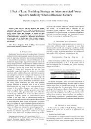
For the cases <strong>in</strong>clud<strong>in</strong>g arrester, it can be seen that<br />
ferroresonant drop out will be occurred. Figs. 2, 3 and 4 show<br />
the phase plan diagram of system states without arrester for<br />
E=3 pu. Figs. 4, 5 and 6 show the bifurcation diagram<br />
without arrester for E=1-6 pu which depicts chaotic behavior.<br />
V oltage of Transform er<br />
8<br />
6<br />
4<br />
2<br />
0<br />
-2<br />
-4<br />
-6<br />
Phase Plan Diagram with q=7 <strong>in</strong>clud<strong>in</strong>g nonl<strong>in</strong>ear core losses effect&without MOV<br />
-8<br />
-2.5 -2 -1.5 -1 -0.5 0 0.5 1 1.5 2 2.5<br />
Flux L<strong>in</strong>kage of Transformer<br />
Fig. 2. Phase diagram of system <strong>in</strong>clud<strong>in</strong>g nonl<strong>in</strong>ear core losses and<br />
without MOV, q=7<br />
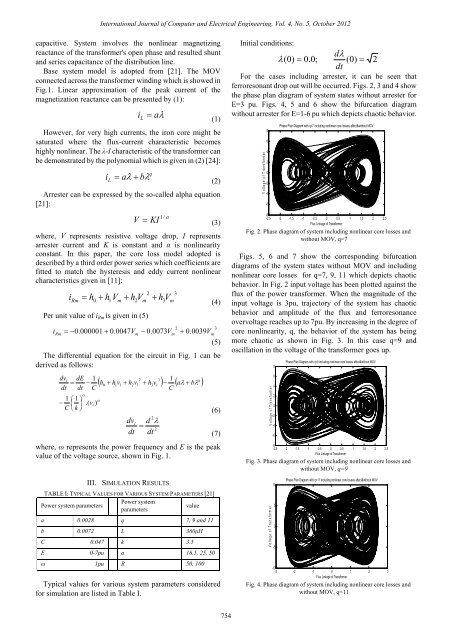
Figs. 5, 6 and 7 show the correspond<strong>in</strong>g bifurcation<br />
diagrams of the system states without MOV and <strong>in</strong>clud<strong>in</strong>g<br />
nonl<strong>in</strong>ear core losses for q=7, 9, 11 which depicts chaotic<br />
behavior. In Fig. 2 <strong>in</strong>put voltage has been plotted aga<strong>in</strong>st the<br />
flux of the power transformer. When the magnitude of the<br />
<strong>in</strong>put voltage is 3pu, trajectory of the system has chaotic<br />
behavior and amplitude of the flux and ferroresonance<br />
overvoltage reaches up to 7pu. By <strong>in</strong>creas<strong>in</strong>g <strong>in</strong> the degree of<br />
core nonl<strong>in</strong>earity, q, the behavior of the system has be<strong>in</strong>g<br />
more chaotic as shown <strong>in</strong> Fig. 3. In this case q=9 and<br />
oscillation <strong>in</strong> the voltage of the transformer goes up.<br />
V oltage of Transform er<br />
8<br />
6<br />
4<br />
2<br />
0<br />
-2<br />
-4<br />
-6<br />
Phase Plan Diagram with q=9 <strong>in</strong>clud<strong>in</strong>g nonl<strong>in</strong>ear core losses effect&without MOV<br />
-8<br />
-2.5 -2 -1.5 -1 -0.5 0 0.5 1 1.5 2 2.5<br />
Flux L<strong>in</strong>kage of Transformer<br />
Fig. 3. Phase diagram of system <strong>in</strong>clud<strong>in</strong>g nonl<strong>in</strong>ear core losses and<br />
without MOV, q=9<br />
V oltage of Transform er<br />
10<br />
5<br />
0<br />
-5<br />
Phase Plan Diagram with q=11 <strong>in</strong>clud<strong>in</strong>g nonl<strong>in</strong>ear core losses effect&without MOV<br />
-10<br />
-3 -2 -1 0 1 2 3<br />
Flux L<strong>in</strong>kage of Transformer<br />
Fig. 4. Phase diagram of system <strong>in</strong>clud<strong>in</strong>g nonl<strong>in</strong>ear core losses and<br />
without MOV, q=11<br />
754