Ferroresonance Phenomena in Unloaded Transformers ... - ijcee
Ferroresonance Phenomena in Unloaded Transformers ... - ijcee
Ferroresonance Phenomena in Unloaded Transformers ... - ijcee

Create successful ePaper yourself
Turn your PDF publications into a flip-book with our unique Google optimized e-Paper software.
International Journal of Computer and Electrical Eng<strong>in</strong>eer<strong>in</strong>g, Vol. 4, No. 5, October 2012<br />
<strong>Ferroresonance</strong> <strong>Phenomena</strong> <strong>in</strong> <strong>Unloaded</strong> <strong>Transformers</strong><br />
Apply<strong>in</strong>g MOV<br />
Hamid Radmanesh, Mat<strong>in</strong> Nademi, and Maryam Nademi<br />
<br />
Abstract—This Paper studies the effect of a parallel Metal<br />
Oxide Varistor (MOV) on the ferroresonance oscillations of the<br />
transformer <strong>in</strong>clud<strong>in</strong>g nonl<strong>in</strong>ear core losses. It is expected that<br />
the arresters generally cause ferroresonance ‘dropout'.<br />
Time-doma<strong>in</strong> simulation has been carried out us<strong>in</strong>g MATLAB<br />
SIMULINK to study this effect. Simulation has been done on a<br />
three phase unloaded transformer with one open phase. Effect<br />
of vary<strong>in</strong>g <strong>in</strong>put voltage has been studied. The simulation<br />
results reveal that connect<strong>in</strong>g the arrester to the transformer<br />
poles, exhibits a great mitigat<strong>in</strong>g effect on ferroresonant<br />
overvoltages. Phase plan along with bifurcation diagrams are<br />
also presented. Significant effect on the onset of chaos, the range<br />
of parameter values that may lead to chaos and magnitude of<br />
ferroresonant voltages has been obta<strong>in</strong>ed, showed and<br />
tabulated.<br />
Index Terms—Power transformer, nonl<strong>in</strong>ear core losses<br />
effect, chaos, ferroresonance, Metal Oxide Varistor (MOV)<br />
I. INTRODUCTION<br />
In simple terms, ferroresonance is a series of resonance<br />
<strong>in</strong>volv<strong>in</strong>g nonl<strong>in</strong>ear <strong>in</strong>ductance and capacitances. It typically<br />
<strong>in</strong>volves the saturable magnetiz<strong>in</strong>g <strong>in</strong>ductance of a<br />
transformer and a capacitive distribution cable or<br />
transmission l<strong>in</strong>e connected to the transformer. Its occurrence<br />
is more likely to happen <strong>in</strong> the absence of adequate damp<strong>in</strong>g.<br />
Research <strong>in</strong>volv<strong>in</strong>g ferroresonance <strong>in</strong> transformers has been<br />
conducted over the last 80 years. The word ferroresonance<br />
first appeared <strong>in</strong> the literature <strong>in</strong> 1920 [1], although papers on<br />
resonance <strong>in</strong> transformers appeared as early as 1907 [2].<br />
Practical <strong>in</strong>terest was generated <strong>in</strong> the 1930’s when it was<br />
shown use of series capacitors for voltage regulation caused<br />
ferroresonance <strong>in</strong> distribution systems [3], result<strong>in</strong>g <strong>in</strong><br />
damag<strong>in</strong>g overvoltages. The first analytical work was done<br />
by Rudenberg <strong>in</strong> the 1940’s [4]. More precise and detailed<br />
work was done later by Hayashi <strong>in</strong> the 1950’s [5].<br />
Subsequent research has been divided <strong>in</strong>to two ma<strong>in</strong> areas:<br />
improv<strong>in</strong>g the transformer models and study<strong>in</strong>g<br />
ferroresonance at the system level. An understand<strong>in</strong>g of the<br />
nonl<strong>in</strong>ear parameters describ<strong>in</strong>g a transformer core is<br />
prerequisite to deal<strong>in</strong>g with ferroresonance. Swift [6] and<br />
Jiles [7] provide <strong>in</strong>sights <strong>in</strong>to transformer core behaviour and<br />
the separation of hysteresis and eddy current losses. Frame<br />
[8] and others have developed piecewise-l<strong>in</strong>ear methods of<br />
modell<strong>in</strong>g the nonl<strong>in</strong>earities <strong>in</strong> saturable <strong>in</strong>ductances.<br />
Manuscript received September 12, 2012; revised October 25, 2012.<br />
Hamid Radmanesh is with Electrical Eng<strong>in</strong>eer<strong>in</strong>g Department, Shahab<br />
Danesh Institute of Higher Education, ghom, Iran(e-mail:<br />
Hamid.radmanesh@aut.ac.ir).<br />
Mat<strong>in</strong> Nademi and M. Nademi are with Department of Electrical<br />
Eng<strong>in</strong>eer<strong>in</strong>g, Islamic Azad University, Takestan Branch, Takestan,<br />
Iran(e-mail: hrbscstudent@gmail.com; mam.nademi@gmail.com).<br />
Hopk<strong>in</strong>son [9] performed system tests and simulations on the<br />
effect of different switch<strong>in</strong>g strategies on the <strong>in</strong>itiation of<br />
ferroresonance <strong>in</strong> three-phase systems. Smith [10]<br />
categorized the modes of ferroresonance <strong>in</strong> one type of<br />
three-phase distribution transformer based on the magnitude<br />
and appearance of the voltage waveforms. Abrupt transition<br />
or jump from one state to another is triggered by a<br />
disturbance, switch<strong>in</strong>g action or a gradual change <strong>in</strong> values of<br />
a parameter. Typical cases of ferroresonance are reported <strong>in</strong><br />
[11], [12]. The theory of nonl<strong>in</strong>ear dynamics has been<br />
<strong>in</strong>troduced to provide deeper <strong>in</strong>sight <strong>in</strong>to the phenomenon<br />
[13]. Fundamental theory of nonl<strong>in</strong>ear dynamics and chaos<br />
can be found <strong>in</strong> [12], [14]. The susceptibility of a<br />
ferroresonance circuit to a quasi periodic and frequency<br />
locked oscillations are presented <strong>in</strong> [15], [16]. Paper <strong>in</strong> [17]<br />
<strong>in</strong>vestigated the effect of transformer model<strong>in</strong>g on the<br />
predicted ferroresonance oscillations. Us<strong>in</strong>g a l<strong>in</strong>ear model,<br />
[18] have brought the effect of core loss <strong>in</strong> damp<strong>in</strong>g<br />
ferroresonance oscillations. In [19] emphasizes treat<strong>in</strong>g core<br />
loss as a nonl<strong>in</strong>ear function of voltage on transformer. An<br />
algorithm for calculat<strong>in</strong>g core losses based on no-load<br />
characteristics of transformer is given <strong>in</strong> [20]. The mitigat<strong>in</strong>g<br />
effect of transformer connected <strong>in</strong> parallel to a MOV is<br />
illustrated <strong>in</strong> [21]. Analyze chaotic ferroresonance<br />
phenomena <strong>in</strong> power transformers <strong>in</strong>clud<strong>in</strong>g neutral<br />
resistance effect have been given <strong>in</strong> [22]. Effect of circuit<br />
breaker shunt resistance on chaotic ferroresonance <strong>in</strong> voltage<br />
transformer has been studied <strong>in</strong> [23]. In all previous studies,<br />
the effects of MOV on power transformer <strong>in</strong>clud<strong>in</strong>g<br />
nonl<strong>in</strong>ear core losses are neglected. In previous works, it has<br />
been shown that nonl<strong>in</strong>ear core loss can decrease<br />
ferroresonance phenomena <strong>in</strong> power transformer [24]. This<br />
paper studies the effect of MOV on the global behaviour of a<br />
ferroresonance circuit with nonl<strong>in</strong>ear core loss.<br />
i<br />
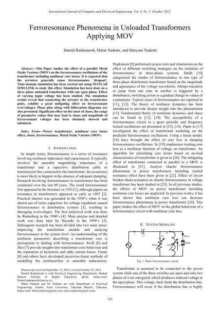
II. SYSTEM MODELING<br />
C<br />
E Rcore Lcore<br />
Fig. 1. Basic ferroresonance circuit<br />
i1<br />
i2<br />
V<br />
iMOSA<br />
MOSA<br />
Transformer is assumed to be connected to the power<br />
system while one of the three switches are open and only two<br />
phases of it are energized, which produces <strong>in</strong>duced voltage <strong>in</strong><br />
the open phase. This voltage, back feeds the distribution l<strong>in</strong>e.<br />
<strong>Ferroresonance</strong> will occur if the distribution l<strong>in</strong>e is highly<br />
753
International Journal of Computer and Electrical Eng<strong>in</strong>eer<strong>in</strong>g, Vol. 4, No. 5, October 2012<br />
capacitive. System <strong>in</strong>volves the nonl<strong>in</strong>ear magnetiz<strong>in</strong>g<br />
reactance of the transformer's open phase and resulted shunt<br />
and series capacitance of the distribution l<strong>in</strong>e.<br />
Base system model is adopted from [21]. The MOV<br />
connected across the transformer w<strong>in</strong>d<strong>in</strong>g which is showed <strong>in</strong><br />
Fig.1. L<strong>in</strong>ear approximation of the peak current of the<br />
magnetization reactance can be presented by (1):<br />
i L<br />
= aλ<br />
However, for very high currents, the iron core might be<br />
saturated where the flux-current characteristic becomes<br />
highly nonl<strong>in</strong>ear. The λ-I characteristic of the transformer can<br />
be demonstrated by the polynomial which is given <strong>in</strong> (2) [24]:<br />
i<br />
L<br />
q<br />
= aλ + bλ<br />
Arrester can be expressed by the so-called alpha equation<br />
[21]:<br />
(1)<br />
(2)<br />
1/ α<br />
V = KI<br />
(3)<br />
where, V represents resistive voltage drop, I represents<br />
arrester current and K is constant and α is nonl<strong>in</strong>earity<br />
constant. In this paper, the core loss model adopted is<br />
described by a third order power series which coefficients are<br />
fitted to match the hysteresis and eddy current nonl<strong>in</strong>ear<br />
characteristics given <strong>in</strong> [11]:<br />
Rm<br />
2 3<br />
0<br />
+ h1<br />
Vm<br />
+ h2V<br />
m<br />
h3V<br />
m<br />
i = h<br />
+<br />
Per unit value of i Rm is given <strong>in</strong> (5)<br />
Rm<br />
2<br />
3<br />
0.000001<br />
+ 0.0047Vm<br />
− 0.0073V<br />
m<br />
0.0039Vm<br />
i = −<br />
+<br />
The differential equation for the circuit <strong>in</strong> Fig. 1 can be<br />
derived as follows:<br />
dvl<br />
dE<br />
=<br />
dt dt<br />
1 ⎛ 1 ⎞<br />
− ⎜ ⎟<br />
C ⎝ k ⎠<br />
α<br />
.( v )<br />
α<br />
l<br />
2 1<br />
q<br />
( h + h v + h v + h v ) − ( aλ<br />
+ bλ<br />
)<br />
1 3<br />
0 1 l 2 l 3 l<br />
−<br />
C<br />
dv l<br />
dt<br />
2<br />
d λ<br />
=<br />
2<br />
dt<br />
where, ω represents the power frequency and E is the peak<br />
value of the voltage source, shown <strong>in</strong> Fig. 1.<br />
III. SIMULATION RESULTS<br />
TABLE I: TYPICAL VALUES FOR VARIOUS SYSTEM PARAMETERS [21]<br />
Power system<br />
Power system parameters<br />
value<br />
parameters<br />
a 0.0028 q 7, 9 and 11<br />
b 0.0072 L 360μH<br />
C 0.047 k 3.5<br />
E 0-7pu α 16.5, 25, 50<br />
ω 1pu R 50, 100<br />
Typical values for various system parameters considered<br />
for simulation are listed <strong>in</strong> Table I.<br />
C<br />
(4)<br />
(5)<br />
(6)<br />
(7)<br />
Initial conditions:<br />
dλ<br />
λ( 0) = 0.0; (0) = 2<br />
dt<br />
For the cases <strong>in</strong>clud<strong>in</strong>g arrester, it can be seen that<br />
ferroresonant drop out will be occurred. Figs. 2, 3 and 4 show<br />
the phase plan diagram of system states without arrester for<br />
E=3 pu. Figs. 4, 5 and 6 show the bifurcation diagram<br />
without arrester for E=1-6 pu which depicts chaotic behavior.<br />
V oltage of Transform er<br />
8<br />
6<br />
4<br />
2<br />
0<br />
-2<br />
-4<br />
-6<br />
Phase Plan Diagram with q=7 <strong>in</strong>clud<strong>in</strong>g nonl<strong>in</strong>ear core losses effect&without MOV<br />
-8<br />
-2.5 -2 -1.5 -1 -0.5 0 0.5 1 1.5 2 2.5<br />
Flux L<strong>in</strong>kage of Transformer<br />
Fig. 2. Phase diagram of system <strong>in</strong>clud<strong>in</strong>g nonl<strong>in</strong>ear core losses and<br />
without MOV, q=7<br />
Figs. 5, 6 and 7 show the correspond<strong>in</strong>g bifurcation<br />
diagrams of the system states without MOV and <strong>in</strong>clud<strong>in</strong>g<br />
nonl<strong>in</strong>ear core losses for q=7, 9, 11 which depicts chaotic<br />
behavior. In Fig. 2 <strong>in</strong>put voltage has been plotted aga<strong>in</strong>st the<br />
flux of the power transformer. When the magnitude of the<br />
<strong>in</strong>put voltage is 3pu, trajectory of the system has chaotic<br />
behavior and amplitude of the flux and ferroresonance<br />
overvoltage reaches up to 7pu. By <strong>in</strong>creas<strong>in</strong>g <strong>in</strong> the degree of<br />
core nonl<strong>in</strong>earity, q, the behavior of the system has be<strong>in</strong>g<br />
more chaotic as shown <strong>in</strong> Fig. 3. In this case q=9 and<br />
oscillation <strong>in</strong> the voltage of the transformer goes up.<br />
V oltage of Transform er<br />
8<br />
6<br />
4<br />
2<br />
0<br />
-2<br />
-4<br />
-6<br />
Phase Plan Diagram with q=9 <strong>in</strong>clud<strong>in</strong>g nonl<strong>in</strong>ear core losses effect&without MOV<br />
-8<br />
-2.5 -2 -1.5 -1 -0.5 0 0.5 1 1.5 2 2.5<br />
Flux L<strong>in</strong>kage of Transformer<br />
Fig. 3. Phase diagram of system <strong>in</strong>clud<strong>in</strong>g nonl<strong>in</strong>ear core losses and<br />
without MOV, q=9<br />
V oltage of Transform er<br />
10<br />
5<br />
0<br />
-5<br />
Phase Plan Diagram with q=11 <strong>in</strong>clud<strong>in</strong>g nonl<strong>in</strong>ear core losses effect&without MOV<br />
-10<br />
-3 -2 -1 0 1 2 3<br />
Flux L<strong>in</strong>kage of Transformer<br />
Fig. 4. Phase diagram of system <strong>in</strong>clud<strong>in</strong>g nonl<strong>in</strong>ear core losses and<br />
without MOV, q=11<br />
754
International Journal of Computer and Electrical Eng<strong>in</strong>eer<strong>in</strong>g, Vol. 4, No. 5, October 2012<br />
Fig. 4 shows the Phase plan diagram has been simulated by<br />
q=11. It shows that chaotic resonance is highly dependent on<br />
the transformer model<strong>in</strong>g.<br />
Another tool that can show manner of the system <strong>in</strong> vast<br />
variation of parameters is bifurcation diagram. In Fig. 5,<br />
voltage of the system has been <strong>in</strong>creased to 6pu and<br />
ferroresonance has been begun <strong>in</strong> 4pu, it is shown that if<br />
<strong>in</strong>put voltage goes up due to the abnormal operation or<br />
switch<strong>in</strong>g action, ferroresonance occurs, because of the<br />
nonl<strong>in</strong>earity <strong>in</strong> core losses, ferroresonance began <strong>in</strong> the big<br />
value of the <strong>in</strong>put voltage.<br />
Voltage of Transform er<br />
2.5<br />
2<br />
1.5<br />
1<br />
0.5<br />
Bifurcation Diagram with q=7 Includ<strong>in</strong>g NonL<strong>in</strong>ear Core Losses&without MOV<br />
0<br />
0 1 2 3 4 5 6<br />
Input Voltage(perunit)<br />
Fig. 5. Bifurcation diagram with q=7, without MOV<br />
Fig. 5 shows the abnormal phenomena <strong>in</strong> the unloaded<br />
transformer with the core model nonl<strong>in</strong>earity q=7, it clearly<br />
shows when the q degree changes from 7 to 9; ferroresonance<br />
beg<strong>in</strong>s <strong>in</strong> 3.9 pu. By compar<strong>in</strong>g Fig. 6 with Fig. 7, it is clear<br />
that marg<strong>in</strong> of the beg<strong>in</strong>n<strong>in</strong>g ferroresonance has been<br />
decreased.<br />
Voltage of Transformer<br />
Voltage of Transformer<br />
2<br />
1.8<br />
1.6<br />
1.4<br />
1.2<br />
1<br />
0.8<br />
0.6<br />
0.4<br />
0.2<br />
Bifurcation Diagram with q=9 Includ<strong>in</strong>g NonL<strong>in</strong>ear Core Losses&without MOV<br />
0<br />
0 1 2 3 4 5 6<br />
Input Voltage(perunit)<br />
1.8<br />
1.6<br />
1.4<br />
1.2<br />
1<br />
0.8<br />
0.6<br />
0.4<br />
0.2<br />
Fig. 6. Bifurcation diagram with q=9, without MOV<br />
Bifurcation Diagram with q=11 Includ<strong>in</strong>g NonL<strong>in</strong>ear Core Losses&without MOV<br />
0<br />
0 1 2 3 4 5 6<br />
Input Voltage(perunit)<br />
Fig. 7. Bifurcation diagram with q=11, without MOV<br />
Fig. 7 shows the bifurcation diagram of the overvoltage<br />
with q=11. It shows that with q=11, system behavior reaches<br />
to 1.6 pu.<br />
Figs. 8, 9 and 10 show the correspond<strong>in</strong>g phase diagram<br />
for the system <strong>in</strong> Fig. 1. Also, Figs. 11, 12 and 13 show the<br />
bifurcation diagrams for correspond<strong>in</strong>g system <strong>in</strong>clud<strong>in</strong>g<br />
MOV. It is shown that chaotic region mitigates by apply<strong>in</strong>g<br />
MOV.<br />
Voltage of Transformer<br />
2.5<br />
2<br />
1.5<br />
1<br />
0.5<br />
0<br />
-0.5<br />
-1<br />
-1.5<br />
-2<br />
Phase Plan Diagram with q=7 <strong>in</strong>clud<strong>in</strong>g Nonl<strong>in</strong>ear core losses and MOV effect<br />
-2.5<br />
-2 -1.5 -1 -0.5 0 0.5 1 1.5 2<br />
Flux L<strong>in</strong>kage of Transformer<br />
Fig. 8. Phase plan diagram of system with q=7, apply<strong>in</strong>g MOV<br />
The use of geometric graphical methods like phase plan<br />
projections and bifurcation can be applied to obta<strong>in</strong> a better<br />
understand<strong>in</strong>g of ferroresonance. Figs. 11, 12 and 13 show<br />
the bifurcation diagrams for correspond<strong>in</strong>g system <strong>in</strong>clud<strong>in</strong>g<br />
MOV. It is shown that chaotic region mitigates by apply<strong>in</strong>g<br />
MOV. This occurs more typically for very large values of q.<br />
Voltage of Transformer<br />
Voltage of Transformer<br />
2.5<br />
2<br />
1.5<br />
1<br />
0.5<br />
0<br />
-0.5<br />
-1<br />
-1.5<br />
-2<br />
Phase Plan Diagram with q=9 <strong>in</strong>clud<strong>in</strong>g Nonl<strong>in</strong>ear core losses and MOV effect<br />
-2.5<br />
-2 -1.5 -1 -0.5 0 0.5 1 1.5 2<br />
Flux L<strong>in</strong>kage of Transformer<br />
Fig. 9. Phase plan diagram of system with q=9, apply<strong>in</strong>g MOV<br />
2.5<br />
2<br />
1.5<br />
1<br />
0.5<br />
0<br />
-0.5<br />
-1<br />
-1.5<br />
-2<br />
Phase Plan Diagram with q=11 <strong>in</strong>clud<strong>in</strong>g Nonl<strong>in</strong>ear core losses and MOV effect<br />
-2.5<br />
-2 -1.5 -1 -0.5 0 0.5 1 1.5 2<br />
Flux L<strong>in</strong>kage of Transformer<br />
Fig. 10. Phase plan diagram of system with q=11, <strong>in</strong>clud<strong>in</strong>g MOV<br />
In Fig. 11, the degree of transformer core is q=7, <strong>in</strong> this<br />
figure, one jump has occurred <strong>in</strong> the trajectory of the system<br />
and voltage of the transformer has period-3 oscillation.<br />
755
International Journal of Computer and Electrical Eng<strong>in</strong>eer<strong>in</strong>g, Vol. 4, No. 5, October 2012<br />
Voltage of Transformer<br />
1.8<br />
1.6<br />
1.4<br />
1.2<br />
1<br />
0.8<br />
0.6<br />
0.4<br />
0.2<br />
Bifurcation Diagram with q=7 Includ<strong>in</strong>g NonL<strong>in</strong>ear Core Losses and MOV<br />
simulated are very close for the period’s one, two, and three.<br />
Period five is generally correct, with slightly lower than<br />
actual peak amplitudes predicted. The chaotic response<br />
predicted is slightly higher than the actual one. The model<br />
used a simplistic l<strong>in</strong>ear resistance to represent the core losses<br />
of each core. The system has been greatly affected by arrester<br />
parameter. Ma<strong>in</strong>ta<strong>in</strong><strong>in</strong>g same parameters, except transformer<br />
losses, simulations repeated, which showed that the tendency<br />
to fall <strong>in</strong> chaotic regions <strong>in</strong>creases while, core losses<br />
decreases.<br />
Voltage of Transformer<br />
0<br />
0 1 2 3 4 5 6<br />
Input Voltage(perunit)<br />
1.5<br />
0.5<br />
Fig. 11. Bifurcation diagram with q=7, apply<strong>in</strong>g MOV<br />
1<br />
Bifurcation Diagram with q=9 Includ<strong>in</strong>g NonL<strong>in</strong>ear Core Losses and MOV<br />
IV. CONCLUSION<br />
The dynamic behaviour of a transformer can be<br />
characterized by multiple solutions. Inclusion of nonl<strong>in</strong>earity<br />
<strong>in</strong> the core loss reveals that bifurcation diagrams will be<br />
smoother when compared with l<strong>in</strong>ear models. It has been<br />
shown that system has been greatly affected by MOV. The<br />
presence of the MOV results <strong>in</strong> clamp<strong>in</strong>g the <strong>Ferroresonance</strong><br />
over voltages <strong>in</strong> studied system. The MOV successfully,<br />
suppresses or elim<strong>in</strong>ates the chaotic behaviour of proposed<br />
model. Consequently, the system shows less sensitivity to<br />
<strong>in</strong>itial conditions <strong>in</strong> the presence of the MOV.<br />
0<br />
0 1 2 3 4 5 6<br />
Input Voltage(perunit)<br />
Fig. 12. Bifurcation diagram with q=9, apply<strong>in</strong>g MOV<br />
In Fig. 12, q=9 and by consider<strong>in</strong>g MOV <strong>in</strong> the system,<br />
there is no nonl<strong>in</strong>ear phenomena and voltage of the<br />
transformer has a period-3 oscillation. By <strong>in</strong>creas<strong>in</strong>g the core<br />
nonl<strong>in</strong>earity, behavior rema<strong>in</strong>s <strong>in</strong> periodic oscillation and<br />
MOV can cause ferroresonance drop out.<br />
Voltage of Transformer<br />
1.4<br />
1.2<br />
1<br />
0.8<br />
0.6<br />
0.4<br />
0.2<br />
Bifurcation Diagram with q=11 Includ<strong>in</strong>g NonL<strong>in</strong>ear Core Losses and MOV<br />
0<br />
0 1 2 3 4 5 6<br />
Input Voltage(perunit)<br />
Fig. 13. Bifurcation diagram with q=11, apply<strong>in</strong>g MOV<br />
A bifurcation is essentially a jump from one mode of<br />
ferroresonance to another. A simulation technique was<br />
developed to very slowly ramp the capacitance and record<br />
jumps from one mode to another. Due to nonl<strong>in</strong>earities, it is<br />
important to ramp the capacitance both upward and<br />
downward, to ensure that as many ferroresonance modes are<br />
discovered as possible. “Period 3” simply means that the<br />
waveform takes three periods of the forc<strong>in</strong>g function to<br />
repeat, it conta<strong>in</strong>s 1/3 harmonics. The model correctly<br />
predicts the existence of all modes of ferroresonance at the<br />
correct values of capacitance. The actual waveforms<br />
ACKNOWLEDGMENT<br />
Correspond<strong>in</strong>g author would like to appriciate Dr. Ali<br />
Nasrabadi of the Shahed University, Tehran, Iran, for<br />
provid<strong>in</strong>g MATLAB data files for the time doma<strong>in</strong><br />
simulations, and Mrs. Leila Kharazmi for her English edit<strong>in</strong>g.<br />
REFERENCES<br />
[1] B. A. Mork and D. L. Stuehm, “Application of nonl<strong>in</strong>ear dynamics<br />
and chaos to ferroresonance <strong>in</strong> distribution systems,” IEEE<br />
Transactions on Power Delivery, vol. 9, 1994.<br />
[2] J. Bethenod, “Sur le transformateur et résonance,” L’Eclairae<br />
Electrique, pp. 289–296, Nov. 30, 1907.<br />
[3] J. W. Butler and C. Concordia, “Analysis of series capacitor<br />
application problems,” AIEE Trans, vol. 56, pp. 975–988, Aug. 1937.<br />
[4] R. Rudenberg, Transient Performance of Electric Power Systems. New<br />
York, NY: McGraw-Hill Book Company, 1950, ch. 48.<br />
[5] C. Hayashi, Nonl<strong>in</strong>ear Oscillations <strong>in</strong> Physical Systems. New York,<br />
NY: McGraw-Hill Book Company, 1964.<br />
[6] R. A. Wall<strong>in</strong>g, K. D. Barker, T. M. Compton, and L. E. Zimmerman,<br />
“<strong>Ferroresonance</strong> over voltages <strong>in</strong> grounded wye-wye pad mount<br />
transformers with low-loss silicon-steel cores,” IEEE Trans. Power<br />
Delivery, vol. 8, no. 3, pp. 1647–1660, July 1993.<br />
[7] D. C. Jiles and D. L. Atherton, “Theory of ferromagnetic hysteresis,”<br />
<strong>in</strong> Journal of Magnetism and Magnetic Materials: Elsevier Science<br />
Publishers B.V, Jan. 21, 1986, vol. 61, pp. 48–60.<br />
[8] J. G. Frame, N. Mohan, and T. Liu, “Hysteresis model<strong>in</strong>g <strong>in</strong> an<br />
electromagnetic transients program,” IEEE Trans. PAS, vol. PAS-101,<br />
no. 9, pp. 3403–3411, Sept. 1982.<br />
[9] R. H. Hopk<strong>in</strong>son, “<strong>Ferroresonance</strong> dur<strong>in</strong>g s<strong>in</strong>gle-phase switch<strong>in</strong>g of<br />
3-phase distribution transformer banks,” IEEE Trans. PAS, vol.<br />
PAS-84, no. 4, pp. 289–293, Apr. 1965.<br />
[10] NRECA, Underground Distribution System Design and Installation<br />
Guide: National Rural Electric Cooperatives Association, 1994, sec. 6.<br />
[11] H. W. Dommel, A. Yan, R. J. O. D. Marcano, and A. B. Miliani, <strong>in</strong>:<br />
H.P. Kh<strong>in</strong>cha(Ed.), Tutorial Course on Digital Simulation of Transients<br />
<strong>in</strong> Power Systems (Chapter 14), IISc, Bangalore, 1983, pp. 17-/38.<br />
[12] C. Kieny, “Application of the bifurcation theory <strong>in</strong> study<strong>in</strong>g and<br />
understand<strong>in</strong>g the global behavior of a ferroresonance electric power<br />
circuit,” IEEE Transactions on Power Delivery, vol. 6, 1991, pp.<br />
866-872.<br />
[13] A. E. Araujo, A. C. Soudack, and J. R. Marti, “<strong>Ferroresonance</strong> <strong>in</strong><br />
power systems: chaotic behaviour,” IEE Proceed<strong>in</strong>gs-C 140, 1993, pp.<br />
237-240.<br />
756
International Journal of Computer and Electrical Eng<strong>in</strong>eer<strong>in</strong>g, Vol. 4, No. 5, October 2012<br />
[14] B. A. Mork and D. L. Stuehm, “Application of nonl<strong>in</strong>ear dynamics<br />
and chaos to ferroresonance <strong>in</strong> distribution systems,” IEEE<br />
Transactions on Power Delivery, vol. 9, 1994, pp. 1009-1017.<br />
[15] S. K. Chkravarthy and C. V. Nayar, “Frequency-locked and quasi<br />
periodic (QP) oscillations <strong>in</strong> power systems,” IEEE Transactions on<br />
Power Delivery, vol. 13, 1997, pp. 560-569.<br />
[16] S. Mozaffari, M. Sameti, and A. C. Soudack, “Effect of <strong>in</strong>itial<br />
conditions on chaotic ferroresonance <strong>in</strong> power transformers,” IEE<br />
Proceed<strong>in</strong>gs*/Generation, Transmission and Distribution, vol. 144,<br />
1997, pp. 456-460.<br />
[17] B. A. Mork,” Five-legged wound*/core transformer model: derivation,<br />
parameters, implementation, and evaluation,” IEEE Transactions on<br />
Power Delivery, vol.14, 1999, pp. 1519-1526.<br />
[18] B. A. T. A. Zahawi, Z. Em<strong>in</strong>, and Y. K. Tong, “Chaos <strong>in</strong><br />
ferroresonance wound voltage transformers: effect of core losses and<br />
universal circuit behavioral,” IEE Proceed<strong>in</strong>gs*/Sci. Meas. Technol,<br />
vol. 145, 1998, pp. 39-43.<br />
[19] IEEE Work<strong>in</strong>g Group on Model<strong>in</strong>g and Analysis of Systems Transients,<br />
M.R. Iravani, Chair, Model<strong>in</strong>g and analysis guidel<strong>in</strong>es for slow<br />
transients*/part III: the study of ferroresonance, IEEE Transactions on<br />
Power Delivery, vol. 15, 2000, pp. 255-265.<br />
[20] W. L. A. Neves and H. Dommel, “on model<strong>in</strong>g iron core<br />
nonl<strong>in</strong>earities,” IEEE Transactions on Power Systems, vol. 8, 1993, pp.<br />
417-425.<br />
[21] K. A. Anbarri, R. Ramanujam, T. Keerthiga, and K. Kuppusamy,<br />
“Analysis of nonl<strong>in</strong>ear phenomena <strong>in</strong> MOV connected <strong>Transformers</strong>,”<br />
IEE Proceed<strong>in</strong>gs Generation Transmission and Distribution, vol. 148,<br />
2001, pp. 562-566.<br />
[22] H. Radmanesh, A. Abassi, and M. Rostami, "Analysis of<br />
ferroresonance phenomena <strong>in</strong> power transformers <strong>in</strong>clud<strong>in</strong>g neutral<br />
resistance effect," Southeastcon, 2009. SOUTHEASTCON '09. IEEE,<br />
pp.1-5, 5-8 March 2009.<br />
[23] H. Radmanesh and M. Rostami, "Effect of Circuit Breaker Shunt<br />
Resistance on Chaotic <strong>Ferroresonance</strong> <strong>in</strong> Voltage Transformer,"<br />
Advances <strong>in</strong> Electrical and Computer Eng<strong>in</strong>eer<strong>in</strong>g, vol. 10, no. 3, pp.<br />
71-77, 2010.<br />
[24] H. Radmanesh, M. Rostami, and A. Abassi, "Effect of circuit breaker<br />
shunt resistance on ferroresonance phenomena <strong>in</strong> voltage transformer,"<br />
Southeastcon, 2009. SOUTHEASTCON '09. IEEE, pp.183-188, 5-8<br />
March 2009.<br />
Hamid Radmanesh was born <strong>in</strong> 1981. He studied<br />
Telecommunication eng<strong>in</strong>eer<strong>in</strong>g at Malek-Ashtar<br />
University of Technology, Tehran, Iran, and received<br />
the BSC degree <strong>in</strong> 2006, also studied electrical<br />
eng<strong>in</strong>eer<strong>in</strong>g at Shahed University Tehran, Iran, and<br />
received the MSC degree <strong>in</strong> 2009. Currently, He is<br />
PhD student <strong>in</strong> Amirkabir University of Technology.<br />
His research <strong>in</strong>terests <strong>in</strong>clude design and model<strong>in</strong>g of<br />
power electronic converters, drives, transient and<br />
chaos <strong>in</strong> power system apparatus.<br />
757