Adaptivity with moving grids
Adaptivity with moving grids
Adaptivity with moving grids

Create successful ePaper yourself
Turn your PDF publications into a flip-book with our unique Google optimized e-Paper software.
Acta Numerica (2009), pp. 1–131 c○ Cambridge University Press, 2009<br />
doi: 10.1017/S0962492906400015<br />
Printed in the United Kingdom<br />
<strong>Adaptivity</strong> <strong>with</strong> <strong>moving</strong> <strong>grids</strong><br />
Chris J. Budd<br />
Centre for Nonlinear Mechanics,<br />
University of Bath, Bath BA2 7AY, UK<br />
E-mail: mascjb@bath.ac.uk<br />
Weizhang Huang<br />
Department of Mathematics,<br />
University of Kansas,<br />
Lawrence, Kansas 66045, USA<br />
E-mail: huang@math.ku.edu<br />
Robert D. Russell<br />
Department of Mathematics,<br />
Simon Fraser University,<br />
Burnaby V5A 1S6, Canada<br />
E-mail: rdr@cs.sfu.ca<br />
In this article we look at the modern theory of <strong>moving</strong> meshes as part of<br />
an r-adaptive strategy for solving partial differential equations <strong>with</strong> evolving<br />
internal structure. We firstly examine the possible geometries of a <strong>moving</strong><br />
mesh in both one and higher dimensions, and the discretization of partial<br />
differential equation on such meshes. In particular, we consider such issues<br />
as mesh regularity, equidistribution, variational methods, and the error in<br />
interpolating a function or truncation error on such a mesh. We show that,<br />
guided by these, we can design effective <strong>moving</strong> mesh strategies. We then<br />
look in more detail as to how these strategies are implemented. Firstly we<br />
look at position-based methods and the use of <strong>moving</strong> mesh partial differential<br />
equation (MMPDE), variational and optimal transport methods. This<br />
is followed by an analysis of velocity-based methods such as the geometric<br />
conservation law (GCL) methods. Finally we look at a number of examples<br />
where the use of a <strong>moving</strong> mesh method is effective in applications. These<br />
include scale-invariant problems, blow-up problems, problems <strong>with</strong> <strong>moving</strong><br />
fronts and problems in meteorology. We conclude that, whilst r-adaptive<br />
methods are still in a relatively new stage of development, <strong>with</strong> many outstanding<br />
questions remaining, they have enormous potential for development,<br />
and for many problems they represent an optimal form of adaptivity.
2 C. J. Budd, W. Huang and R. D. Russell<br />
CONTENTS<br />
1 Introduction 2<br />
2 Moving mesh basics 10<br />
3 Location-based <strong>moving</strong> mesh methods 44<br />
4 Velocity-based <strong>moving</strong> mesh methods 83<br />
5 Applications of <strong>moving</strong> mesh methods 91<br />
References 121<br />
1. Introduction<br />
1.1. Motivation<br />
Time-dependent systems of partial differential equations (PDEs) often have<br />
structures that evolve significantly as the integration of the PDEs proceeds.<br />
These can be interfaces, shocks, singularities, changes of phase, high vorticity<br />
or regions of complexity. Associated <strong>with</strong> such structures are the<br />
evolution of small length (and time) scales, rapid movement of the solution<br />
features and the possibility of finite time blow-up of a component of the<br />
solution. Frequently associated are also conservation laws, usually linked to<br />
underlying symmetries. Examples of these phenomena occur in many applications,<br />
such as gas and fluid dynamics, conservation laws, nonlinear optics,<br />
free boundary problems, combustion, detonation, meteorology, mathematical<br />
biology and nonlinear optics. To solve such PDEs numerically it is<br />
typical to impose some form of spatial mesh and then to discretize the solution<br />
on this mesh by using a finite element, finite volume, finite difference,<br />
or collocation method. However, this strategy may not be effective in the<br />
case of structures that involve small length scales, leading to large localized<br />
errors. In such cases it is often beneficial to use some form of non-uniform<br />
mesh, adapted to the solution, on which to perform all of the computations.<br />
The advantages of doing this can be a reduced overall error, better conditioning<br />
of the system, and better computational efficiency. Unfortunately,<br />
introducing the extra level of complexity to the system through adaptivity<br />
can also lead to additional computational cost and possible numerical instability.<br />
Mesh adaptation should thus be used <strong>with</strong> care and appropriate<br />
analysis where possible.<br />
1.2. <strong>Adaptivity</strong> on a <strong>moving</strong> mesh<br />
Adaptive methods for solving partial differential equations broadly fit into<br />
three categories. The most extensively developed are static regridding methods,<br />
in which a mesh is updated at each time level. The most widely used of<br />
these are h-refinement methods, which form the basis of many commercial<br />
codes. Usually such codes start <strong>with</strong> an initially uniform mesh, and then
<strong>Adaptivity</strong> <strong>with</strong> <strong>moving</strong> <strong>grids</strong> 3<br />
locally coarsen or refine this by the inclusion or deletion of mesh points. The<br />
strategy for doing this is normally guided by some a posteriori estimate of<br />
the solution error, and may consider problems in which the error is due<br />
to the solution geometry (such as re-entrant corners) or high derivatives.<br />
In p-refinement methods some finite element discretization of the PDE is<br />
used <strong>with</strong> local polynomials of some particular order. This order is then increased<br />
or decreased in accordance <strong>with</strong> the solution error. These methods<br />
may be combined <strong>with</strong> h-refinement methods and <strong>with</strong> careful a posteriori<br />
estimates to give hp methods (Ainsworth and Oden 2000). The principal<br />
objective of the hp methods is to obtain solutions <strong>with</strong>in prescribed error<br />
bounds by such refinement procedures. There is not usually an upper bound<br />
on the number of points used in the calculation. Such methods have now<br />
been developed to a high degree of sophistication. However, they are necessarily<br />
rather complex, need not take advantage of any dynamic properties<br />
of the underlying solution, and the a posteriori error estimates rely heavily<br />
on certain assumptions on the solution which may be hard to verify for<br />
strongly nonlinear problems.<br />
The r-refinement (relocation refinement) <strong>moving</strong> mesh methods which<br />
will form the substance of this article are a more recent development than<br />
hp methods. Whilst not as widely used as h- or p-adaptive methods,<br />
r-adaptivity has been used <strong>with</strong> success in many applications including<br />
computational fluid mechanics (Tang 2005), phase field models and crystal<br />
growth (Mackenzie and Mekwi 2007a), and convective heat transfer<br />
(Ceniceros and Hou 2001). It also has a natural application to problems<br />
<strong>with</strong> a close coupling between spatial and temporal length scales,<br />
such as in problems <strong>with</strong> symmetry, scaling invariance and self-similarity<br />
(Barenblatt 1996, Budd and Williams 2006), where the mesh points become<br />
the natural coordinates for an appropriately rescaled problem. Less is<br />
known about the behaviour of r-adaptive methods than of the much more<br />
extensively developed hp methods, and (at least in higher dimensions) they<br />
have yet to become part of established large numerical codes. In particular,<br />
as we shall see in this article, many outstanding open questions remain on<br />
their convergence, the nature of the meshes that they generate and the error<br />
estimates that can be obtained when using them to solve PDEs <strong>with</strong> rapidly<br />
evolving structures. As a consequence, much of the analysis of such methods<br />
has been for one-dimensional problems, and the one-dimensional PDE<br />
solver MOVCOL (Huang and Russell 1996, Russell, Williams and Xu 2007)<br />
and the celebrated continuation code AUTO (for solving two-point boundary<br />
value problems amongst others) both make use of r-adaptive methods.<br />
However, r-refinement methods show great potential for solving a much<br />
greater range of problems, as we hope to demonstrate in this article.<br />
The r-refinement methods start <strong>with</strong> a uniform mesh and then move the<br />
mesh points, keeping the mesh topology and number of mesh points fixed
4 C. J. Budd, W. Huang and R. D. Russell<br />
as the solution evolves. Hence the use of the alternative name of <strong>moving</strong><br />
mesh methods for such procedures. The mesh points are then concentrated<br />
into regions where the solution has ‘interesting behaviour’, usually typified<br />
by a rapid variation of either the solution or one of its (higher) derivatives.<br />
The objective of this approach is to get the smallest error possible for the<br />
number N of mesh points used, and to try to obtain error estimates which<br />
depend upon the value of N but not on the solution itself. For example,<br />
if the solution evolves a boundary layer of width ɛ (<strong>with</strong> ɛ decreasing as<br />
time advances), then ideally the mesh points should concentrate into this<br />
boundary layer so that the solution error is independent of ɛ. The <strong>moving</strong><br />
mesh methods typically work by generating a mapping from a regular<br />
(logical or computational) domain into a physical domain in which the underlying<br />
equation is posed. The location, or the velocity, of the mesh points<br />
is then determined by solving a system of auxiliary partial differential equations,<br />
often called the <strong>moving</strong> mesh equations. In all cases a vector or a<br />
scalar monitor function (or functions) is used to guide the position of the<br />
mesh. The monitor function is usually designed to give an estimate of some<br />
measure of the solution error which is then equidistributed over each mesh<br />
cell. The monitor function is usually constructed in one of three ways. It<br />
may depend upon a priori solution estimates (such as arclength or curvature),<br />
on a posteriori error estimates (such as the solution residual, as<br />
used in <strong>moving</strong> finite element methods (Baines 1994), or estimates of the<br />
derivative jump across element boundaries (Tang 2005)), or on some underlying<br />
physics related to the solution, such as the potential temperature<br />
or the vorticity in a meteorological problem (Budd and Piggott 2005). In<br />
the case of scale-invariant problems, such physical estimates are often optimal.<br />
When using such methods, much care has to be taken in preventing<br />
mesh tangling and ensuring mesh regularity and isotropy (where relevant).<br />
A discussion of this will form a significant part of Section 2. We also require<br />
that discretizations of the underlying PDE on such meshes (in either<br />
the computational or the physical domain) should retain important properties<br />
of the underlying physical solution, such as conservation laws and<br />
scaling structures (Tang 2005). Provided that these conditions are carefully<br />
considered, r-adaptive methods can be used <strong>with</strong> considerable success for<br />
many time-evolving systems. Examples of these include computational fluid<br />
dynamics (Yanenko, Kroshko, Liseikin, Fomin, Shapeev and Shitov 1976),<br />
groundwater flow (Huang and Zhan 2004, Huang, Zheng and Zhan 2002),<br />
blow-up problems (Budd, Huang and Russell 1996, Budd and Williams 2006,<br />
Ceniceros and Hou 2001, Ren and Wang 2000), chemotaxis systems (Budd,<br />
Carretero-Gonzalez and Russell 2005), reaction–diffusion systems (Zegeling<br />
and Kok 2004), the nonlinear Schrödinger equation (Sulem and Sulem 1999,<br />
Ceniceros 2002, Budd, Chen and Russell 1999a), phase change problems<br />
(Mackenzie and Robertson 2002, Mackenzie and Mekwi 2007a, Tan,Lim
<strong>Adaptivity</strong> <strong>with</strong> <strong>moving</strong> <strong>grids</strong> 5<br />
1<br />
0.9<br />
0.8<br />
0.7<br />
0.6<br />
0.5<br />
0.4<br />
0.3<br />
0.2<br />
0.1<br />
0<br />
0 0.2 0.4 0.6 0.8 1<br />
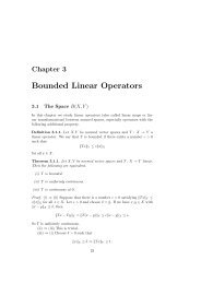
Figure 1.1. A logically rectangular mesh, moved to<br />
concentrate points around a ring in an evolving singular<br />
solution of the nonlinear Schrödinger equation. Note the<br />
good radial symmetry of the adapted mesh around the ring.<br />
and Khoo 2007), shear layer calculations (Tang 2005), gas dynamics (Li<br />
and Petzold 1997, Li, Petzold and Ren 1998), hyperbolic conservation laws<br />
<strong>with</strong> high Mach number (Li and Petzold 1997, Tang 2005, Stockie, Mackenzie<br />
and Russell 2000, Tang and Tang 2003), problems <strong>with</strong> high vorticity<br />
(Ceniceros and Hou 2001), magneto-hydrodynamics (Tan 2007) and meteorological<br />
problems (Budd and Piggott 2005). More details of such applications<br />
are given in Section 5. In Figure 1.1 we give an example of an<br />
r-adaptive mesh which has evolved to capture the structure of a singular<br />
solution of the nonlinear Schrödinger equation which has its support concentrated<br />
around a ring.<br />
All r-adaptive methods have intimate connections <strong>with</strong> the geometry<br />
of mapping one domain to another. They thus have intimate links <strong>with</strong><br />
problems in differential geometry such as optimal transport (Brenier 1991,<br />
Gangbo and McCann 1996), mean curvature flows (Huang 2007) and harmonic<br />
mappings (Dvinsky 1991). A natural application of such ideas arises<br />
in image processing, and r-adaptivity has close connections <strong>with</strong> such image<br />
processing procedures as image segmentation and image de-noising<br />
(Sapiro 2003).<br />
There are advantages and disadvantages to each of the strategies outlined<br />
above. As discussed earlier, the hp methods have been in use for a long time
6 C. J. Budd, W. Huang and R. D. Russell<br />
and are now well established in many commercial codes. There is a significant<br />
body of analysis supporting their use. In contrast, r-adaptive methods<br />
are more recent and are less well understood. A significant criticism which<br />
has often been made of them is that their implementation usually requires<br />
the solution of auxiliary partial differential equations for the mesh, which<br />
must be solved in parallel to the underlying partial differential equation.<br />
This requires significant additional computational cost. Furthermore, the<br />
equations to be solved to determine a suitable mesh can often be very stiff,<br />
and thus expensive to solve. Furthermore, the methods get the best estimates<br />
for a given N rather than errors necessarily lower than a specified<br />
tolerance. However, r-adaptive methods do have significant advantages in<br />
certain applications. Firstly, from a computational point of view, it is convenient<br />
to work <strong>with</strong> the same number of mesh points and the same mesh<br />
topology. This makes the linear algebra rather easier, as the matrices considered<br />
have a constant sparsity structure, and there is no need for any form<br />
of nested data structure to keep track of the node points (an issue which<br />
always complicates the use of h-refinement methods). The discretization<br />
strategy on the mesh is also easier, especially <strong>with</strong> a finite element method,<br />
as the constancy in the mesh topology and connectivity implies that there is<br />
no possibility of hanging nodes. There are further, structural advantages to<br />
r-refinement methods. One of these is that the movement of the mesh points<br />
may well correspond to natural structures of the PDE itself. An obvious example<br />
is Lagrangian-based methods for fluid flow problems, in which mesh<br />
points move <strong>with</strong> the fluid flow. A further such example is given by the use<br />
of r-refinement methods for PDEs <strong>with</strong> natural scaling symmetries, in which<br />
the mesh points automatically follow the motion of natural similarity variables<br />
(and indeed the use of the r-refinement method becomes equivalent<br />
to the use of an appropriate coordinate transformation). A third advantage<br />
of r-refinement is that, under certain circumstances, the adaptive strategy<br />
when coupled <strong>with</strong> the PDE can be regarded as one (large) dynamical system,<br />
which may then be amenable to a combined analysis. One limitation<br />
of having a fixed number of points means that it may never be possible to<br />
resolve all of the fine structures of a PDE as it evolves (although it is surprising<br />
what can be done <strong>with</strong> often a relatively small number of mesh points).<br />
Also, all r-adaptive methods are, in principle, prone to mesh tangling, in<br />
which lines connecting the mesh points can cross over during the evolution.<br />
This generally leads to severe instabilities in the system and a failure of<br />
the solution routine. Mesh tangling is often associated <strong>with</strong> mesh racing,<br />
where some mesh points move very fast during the evolution, frequently<br />
leading to a stiff set of equations to solve. The disadvantages of having to<br />
solve an auxiliary set of partial differential equations are less severe than<br />
they might originally appear to be. Firstly, the combined system of mesh<br />
and underlying equations may be much smaller than the original system
<strong>Adaptivity</strong> <strong>with</strong> <strong>moving</strong> <strong>grids</strong> 7<br />
defined on a uniform mesh for the same level of accuracy. Indeed, in Section<br />
5 we will give an example of the solution of focusing behaviour in the<br />
one-dimensional nonlinear Schrödinger (Sulem and Sulem 1999) equation<br />
(which can be written as four real first-order PDEs), where a discretization<br />
of the PDE on a set of N = 81 <strong>moving</strong> mesh points is able to resolve singular<br />
structures <strong>with</strong> a length scale of 10 −5 , and outperforms discretizations<br />
on uniform meshes <strong>with</strong> 10 5 mesh points. Hence the additional 81 auxiliary<br />
equations for the mesh gives a method which outperforms one <strong>with</strong> 10 5<br />
equations, giving a very significant cost reduction. Secondly, although the<br />
equations describing the mesh are indeed stiff in general, we do not need<br />
(in general) to solve them exactly. After all, it is the underlying solution of<br />
the PDE that we are interested in, and not the mesh on which it is solved.<br />
Thus a quite rough approximation to the solution of the <strong>moving</strong> mesh equations<br />
will often deliver a mesh more than adequate for the task of resolving<br />
the structures of the underlying PDE. Indeed, we will argue in Section 3<br />
(and demonstrate by example in Section 5) that a relaxed version of the<br />
<strong>moving</strong> mesh equations can be solved using a simple explicit method, will<br />
deliver similar performance for much stiffer equations than the meshes obtained<br />
by more computationally expensive methods. Indeed, they may well<br />
be stable, more regular, and deliver a better mesh quality than solving the<br />
exact equations for the mesh. Finally, one of the main applications of hp<br />
methods is to solve otherwise regular PDEs on irregular domains, typically<br />
<strong>with</strong> re-entrant corners, that introduce significant errors due to a lack of<br />
solution regularity at the corner. The r-adaptive methods as described in<br />
this paper are not really the right tool for this job (though see the results<br />
in Touringy (1998)). However, a combination of h and r methods may well<br />
prove optimal in this case, where the h method is used to mesh around the<br />
corner and the r method to follow any evolving solution structure. Future<br />
attempts to combine these two types of adaptive refinement in a general<br />
context should prove to be most interesting.<br />
1.3. Computation on <strong>moving</strong> meshes<br />
The problem of computing solutions of PDEs using a <strong>moving</strong> mesh method<br />
separates into three related problems.<br />
(1) As described, we need some monitor function to guide the mesh evolution,<br />
which is typically constrained either to equidistribute this function,<br />
or to relax towards an equidistributed state. In practice, whatever<br />
the choice of monitor function, some spatial (and temporal) smoothing<br />
is usually employed.<br />
(2) Having determined the monitor function, we must determine a mesh<br />
which equidistributes this in some way. The equidistribution problem<br />
itself is a nonlinear algebraic problem, and a variety of techniques have
8 C. J. Budd, W. Huang and R. D. Russell<br />
been developed to solve this problem such as a variational method, the<br />
geometric conservation law, <strong>moving</strong> mesh PDEs and optimal transport<br />
methods.<br />
(3) The underlying PDE is then discretized, either on the mesh in the<br />
computational domain or in the original physical domain (in the latter<br />
case a finite element or finite volume method is usually employed<br />
(Tang 2005)). The underlying partial differential equation and the<br />
mesh equations can then be solved either simultaneously, typically<br />
by using the method of lines (Huang, Ren and Russell 1994), or alternatively<br />
(often by using a predictor–corrector method). The first<br />
method avoids the need for any interpolation from one mesh to another,<br />
but is usually associated <strong>with</strong> having to solve stiff differential<br />
equations. Alternating solutions can be implemented using either the<br />
quasi-Lagrange approach (Huang and Russell 1997b) or the rezoning<br />
approach (Tang 2005). The former transforms time derivatives to those<br />
along mesh trajectories and avoids interpolation of the physical solution<br />
from the old mesh to the new one. However, it has the disadvantages<br />
that it has to deal <strong>with</strong> extra convection terms caused by mesh<br />
movement and may cause a time lag in mesh movement. On the other<br />
hand, the rezoning approach solves the physical PDE on a fixed mesh<br />
over a time step but requires interpolation from one mesh to another<br />
(which often has to be done very carefully to preserve conservation<br />
laws). We will consider both methods in detail in this article.<br />
We are currently in a situation where the mesh formulation problem, mesh<br />
generation and the solution of PDEs on a <strong>moving</strong> mesh are generally well<br />
understood in one spatial dimension. Reliable and efficient <strong>moving</strong> mesh<br />
methods exist (and are implemented in a number of packages) which are<br />
based on such formulations and can be used to solve time-evolving PDEs<br />
in one spatial dimension, <strong>with</strong> associated error estimates in certain cases.<br />
Indeed, for such problems the use of <strong>moving</strong> mesh PDEs to evolve the mesh<br />
coupled <strong>with</strong> a method of lines approach has proved to be very effective, and<br />
also amenable to analysis. In this article we will be able to give a detailed<br />
description of the theory, implementation and application of such methods.<br />
However, the problem of mesh movement, and the discretization of PDEs<br />
on such meshes, is much less understood in higher dimensions, and this will<br />
form the bulk of the discussion in this paper.<br />
1.4. A historical survey<br />
Moving meshes and the use of adaptive strategies to minimize estimates of<br />
the solution error have a rich and diverse literature. Moving mesh methods<br />
can be classified according to the mesh movement strategy into two groups<br />
(Cao, Huang and Russell 2003): velocity-based methods and location-based
<strong>Adaptivity</strong> <strong>with</strong> <strong>moving</strong> <strong>grids</strong> 9<br />
methods. The first group is referred to as velocity-based since the methods<br />
directly target the mesh velocity and obtain mesh point locations by integrating<br />
the velocity field. Methods in this group are more or less motivated<br />
by the Lagrange method in fluid dynamics, where the mesh coordinates,<br />
defined to follow fluid particles, are obtained by integrating flow velocity. A<br />
major effort in the development of these methods has been to avoid mesh<br />
tangling, an undesired property of the Lagrange method. This type of<br />
method includes those developed in Anderson and Rai (1983), Cao, Huang<br />
and Russell (2002), Liao and Anderson (1992), Miller and Miller (1981),<br />
Miller (1981), Petzold (1987) and Yanenko et al. (1976). The method of<br />
Yanenko et al. (1976) is of Lagrange type. In the work of Anderson and Rai<br />
(1983), mesh movement is based on attraction and repulsion pseudo-forces<br />
between nodes motivated by a spring model in mechanics. The <strong>moving</strong> finite<br />
element method (MFE) of Miller and Miller (1981) and Miller (1981)<br />
has aroused considerable interest. It computes the solution and the mesh<br />
simultaneously by minimizing the residual of the PDEs written in a finite<br />
element form. Penalty terms are added to avoid possible singularities in the<br />
mesh movement equations; see Carlson and Miller (1998a, 1998b). A way<br />
of treating the singularities but <strong>with</strong>out using penalty functions has been<br />
proposed by Wathen and Baines (1985). Liao and Anderson (1992) and<br />
Cai, Fleitas, Jiang and Liao (2004) use a deformation map approach. Cao<br />
et al. (2002) develop the GCL method based on the geometric conservation<br />
law (see Section 4). Similar ideas have been used by Baines, Hubbard<br />
and Jimack (2005) and Baines, Hubbard, Jimack and Jones (2006) for fluid<br />
flow problems.<br />
The second group of <strong>moving</strong> mesh methods is referred to as location-based<br />
because the methods directly control the location of mesh points. Methods<br />
in this group typically employ an adaptation functional and determine the<br />
mesh or the coordinate transformation as a minimizer of the functional. For<br />
example, the method of Dorfi and Drury (1987) can be linked to a functional<br />
associated <strong>with</strong> equidistribution principle (Huang et al. 1994). The<br />
<strong>moving</strong> mesh PDE (MMPDE) method developed in Cao, Huang and Russell<br />
(1999b), Huang et al. (1994) and Huang and Russell (1997a, 1999) moves<br />
the mesh through the gradient flow equation of an adaptation functional,<br />
which includes the energy of a harmonic mapping (Dvinsky 1991) as a special<br />
example. A combination of the MMPDE method <strong>with</strong> local refinement<br />
is studied in Lang, Cao, Huang and Russell (2003). Li, Tang and Zhang<br />
(2002) and Tang and Tang (2003) also use the energy of a harmonic mapping<br />
as their adaptation functional, but discretize the physical PDE in the<br />
rezoning approach.<br />
So far a number of <strong>moving</strong> mesh methods and a variety of variants have<br />
been developed and successfully applied to practical problems; see the review<br />
articles of Cao et al. (2003), Eisman (1985, 1987), Hawken, Gottlieb
10 C. J. Budd, W. Huang and R. D. Russell<br />
and Hansen (1991), Thompson (1985), Thompson, Warsi and Mastin (1982)<br />
and Thompson and Weatherill (1992), and the books of Baines (1994),<br />
Carey (1997), Knupp and Steinberg (1994), Liseikin (1999), Thompson,<br />
Warsi and Mastin (1985) and Zegeling (1993). In particular, Hawken et al.<br />
(1991) give an extensive overview and references on <strong>moving</strong> mesh methods<br />
before 1990. In addition to the references cited above, we would also<br />
like to bring the reader’s attention to the recent interesting work of Bank<br />
and Smith (1997), Beckett, Mackenzie and Robertson (2001a), Budd et al.<br />
(1996), Calhoun, Helzel and LeVeque (2008), Ceniceros and Hou (2001),<br />
Chacón and Lapenta (2006), Lapenta and Chacón (2006), Di, Li, Tang and<br />
Zhang (2005), Huang and Zhan (2004), Mackenzie and Robertson (2002),<br />
Ren and Wang (2000), Stockie et al. (2000), Tang and Tang (2003) and<br />
Zegeling and Kok (2004) on <strong>moving</strong> mesh methods and their applications.<br />
1.5. Outline of this article<br />
The purpose of this Introduction has been to give an underlying motivation<br />
for the theory and application of (adaptive) <strong>moving</strong> meshes. In Section 2<br />
we will consider in detail the geometry of possible meshes (<strong>with</strong> special<br />
regard to equidistribution and isotropy), and the nature of discretizations of<br />
differential equations on them. In Section 3 we then look in detail, and <strong>with</strong><br />
reference to many examples, at ‘location-based’ meshes in which the local<br />
density of the mesh points is controlled by a monitor function. These include<br />
<strong>moving</strong> mesh PDE (MMPDE) methods, variational methods and optimaltransport-based<br />
methods. This discussion will look at <strong>moving</strong> meshes in<br />
both one and higher dimensions and compare the strategies used for these<br />
two cases. In Section 4 we will then look at velocity-based methods, such as<br />
the geometric conservation law (GCL) methods and the <strong>moving</strong> mesh finite<br />
element methods, in which the velocity of the mesh points, rather than their<br />
position, is controlled. The concluding section, Section 5, will then look at<br />
some examples in much more detail, considering scale invariance, blow-up<br />
problems, problems <strong>with</strong> convection and <strong>moving</strong> fronts, phase change and<br />
combustion problems, and problems arising in meteorology.<br />
2. Moving mesh basics<br />
In this section we will give an overview of the main aspects of adaptive<br />
<strong>moving</strong> mesh generation, and will concentrate on the nature of the geometry<br />
of an adapted mesh, the equidistribution and variational approaches to<br />
defining a mesh, and the relation of the mesh to solution (truncation and<br />
interpolation) errors. The movement of the mesh and the way that it can<br />
be coupled to a partial differential equation will be discussed briefly, but will<br />
mainly be the subject of Sections 3 and 4.
<strong>Adaptivity</strong> <strong>with</strong> <strong>moving</strong> <strong>grids</strong> 11<br />
As described in the Introduction, in an r-adaptive procedure a fixed numberofmeshpointsaremoved<br />
in response to some user-designed condition.<br />
Any r-adaptive method has two main features, a description of the optimal<br />
geometry of the mesh (which is related both to intrinsic properties of the<br />
mesh regularity and to the structure of the underlying solution of the PDE)<br />
and a strategy for evolving the mesh towards this optimal geometry. Optimal<br />
mesh geometries are typically expressed in terms of equidistribution<br />
measures (related to the solution of the underlying PDE by monitor functions)<br />
or using variational principles, and we review these here. Movement<br />
strategies are generally methods for determining either the location of the<br />
mesh points or the velocity of the mesh points. We discuss both briefly in<br />
this section, and then in more detail in Sections 3 and 4.<br />
Essential to mesh adaptation is the ability to control the shape, size and<br />
orientation of mesh elements, and hence to control the error of the solution<br />
of the underlying PDE. This is done in three steps. Firstly an estimate<br />
of the solution error and/or mesh quality is made. Secondly the mesh is<br />
aligned and moved according to this estimate. Thirdly the solution of the<br />
underlying PDE is advanced on the new mesh. Typically this can be in<br />
response to some structure of the solution of a PDE which is evolving in the<br />
space supporting the mesh; however, there are more general circumstances<br />
(such as in image processing) where we might wish to evolve a mesh in a<br />
manner independent of any PDE.<br />
In this section we will study the geometry of the meshes that arise from<br />
various adaptive strategies, considering such aspects as local element size,<br />
skewness and orientation as well as considering both isotropic and anisotropic<br />
meshes, and looking at solution error estimation and control.<br />
2.1. Mesh-mapping functions<br />
To describe an r-adaptive mesh we consider a fixed computational domain<br />
Ω C ⊂ R n , in which most of the computations associated <strong>with</strong> the PDE will<br />
be made. The domain Ω C will have the usual Lebesgue measure and may<br />
have a non-trivial topology. We now consider there to be a fixed mesh τ C<br />
on the computational domain. This can either be uniform or non-uniform,<br />
depending on the nature of the underlying problem, and in the simplest<br />
case will be a uniform set of logical rectangles. It can also be triangular,<br />
and usually takes this form when a finite element or finite volume method<br />
is used to discretize the PDE in the physical domain. Alternatively, if<br />
a finite difference or a spectral method is used to discretize the PDE in<br />
the computational domain then a regular rectangular mesh may be more<br />
appropriate. Note that we have a lot of apriorifreedom in the choice<br />
of the computational domain Ω C , and hence when Ω C is simply connected<br />
it is often convenient to consider it to be a logically rectangular domain,
12 C. J. Budd, W. Huang and R. D. Russell<br />
so that<br />
Ω C =[0, 1] n .<br />
To describe a computational mesh in the case of such simply connected<br />
domains we typically divide Ω C ⊂ R n into N n uniform, regular tetrahedra or<br />
cuboids of side proportional to 1/N and volume proportional to 1/N n ,and<br />
we will initially assume that this is the case. In the r-adaptive procedure<br />
considered in this section we consider the mesh points to be joined in a<br />
simple (logically rectangular or triangular) network, the topology of which<br />
(and consequently the ordering of the nodes in the network) is fixed for most<br />
(if not all) of the time during the computation. Indeed, it is this constancy<br />
of ordering which makes the r-adaptive procedure very attractive for finite<br />
element and related computations.<br />
To derive a <strong>moving</strong> mesh, the computational domain <strong>with</strong> its associated<br />
mesh is then mapped to a physical domain Ω P ∈ R n , in which the underlying<br />
PDE is posed. We assume that there is an invertible, adaptive mesh<br />
generating function<br />
F :Ω C → Ω P<br />
describing this map, so that F is smooth on the interior of Ω C and continuous<br />
on Ω C . Throughout this article we will denote variables in Ω C by Greek<br />
letters, e.g., ξ, andinΩ P by Roman letters, x, and consider the function<br />
F(ξ,t)tobetime-dependent. The action of the function F on the fixed<br />
mesh τ C generates a <strong>moving</strong> mesh τ P in the physical domain. An example<br />
of such a mesh is given in Figure 2.1, in which a uniform rectangular mesh<br />
in Ω C is mapped to a mesh τ P . (This map was constructed by using the<br />
optimal transport method described in Section 3.)<br />
In the case where τ C is a uniform rectangular mesh, the resulting mesh<br />
τ P in the physical space is then (in the representative example of a twodimensional<br />
system) given by the points (X i,j ,Y i,j ), where F =(x, y) and<br />
( i<br />
X i,j = x<br />
N , j ) ( i<br />
, Y i,j = y<br />
N N , j )<br />
. (2.1)<br />
N<br />
We assume further that the boundary of ∂Ω C of Ω C is mapped by F to<br />
the boundary of ∂Ω P of Ω P . In some r-adaptive strategies (such as the<br />
multi-equidistribution and/or variational strategies described in Huang and<br />
Russell (1999), the map F is augmented <strong>with</strong> a second map,<br />
∂F : ∂Ω C → Ω P ,<br />
which explicitly describes the map from one boundary to another. This<br />
has the advantage of close control of the meshing strategy right up to the<br />
boundary, but has the disadvantage of introducing extra complexity into<br />
the system. In other algorithms, such as the optimal mapping strategy<br />
(Delzanno, Chacón, Finn, Chung and Lapenta 2008, Budd and Williams
<strong>Adaptivity</strong> <strong>with</strong> <strong>moving</strong> <strong>grids</strong> 13<br />
1<br />
Ω C<br />
1<br />
Ω P<br />
0.9<br />
0.9<br />
0.8<br />
0.8<br />
0.7<br />
0.7<br />
η<br />
0.6<br />
0.5<br />
y<br />
0.6<br />
0.5<br />
0.4<br />
0.4<br />
0.3<br />
0.3<br />
0.2<br />
0.2<br />
0.1<br />
0.1<br />
0<br />
0 0.1 0.2 0.3 0.4 0.5 0.6 0.7 0.8 0.9 1<br />
ξ<br />
0<br />
0 0.1 0.2 0.3 0.4 0.5 0.6 0.7 0.8 0.9 1<br />
x<br />
Figure 2.1. A typical map (x(ξ,η),y(ξ,η)) from a<br />
computational domain Ω C to a physical domain Ω P .<br />
2006), the boundary map is obtained automatically as part of the algorithm.<br />
This is an attractive feature from the perspective of algorithmic complexity,<br />
although it does lead to a reduction of control of the boundary points.<br />
The great merit of this approach is that it transforms the problem of<br />
finding (and describing) a mesh in Ω P (which in the case of h-adaptive<br />
methods can require subtle data structures, including hierarchical trees)<br />
into the much simpler problem of describing the function F. Much of this<br />
article is devoted to deriving suitable equations for F and seeking effective<br />
solution strategies for them. It goes <strong>with</strong>out saying that it should not be<br />
more difficult to find F than to solve the underlying PDE, and indeed that<br />
many such functions F may give appropriate meshes on which to solve<br />
the PDE. The properties of the mesh τ P then follow immediately from the<br />
structure of the map F. This simple observation is a key to the success<br />
of r-adaptive methods, as it allows the use of powerful mathematical tools<br />
to describe, construct and control the mesh behaviour. These include the<br />
application of methods from differential geometry (especially the theory<br />
of optimal transport) to describe the static structure of τ P , and methods<br />
from the theory of dynamical systems to describe its evolution. The latter<br />
is especially appropriate when coupled to the partial differential equations<br />
which are often solved to find F. The unity that r-adaptive meshes give<br />
for both solving the underlying PDE, and finding the mesh, is a significant<br />
advantage of r-adaptivity over other adaptive approaches.
14 C. J. Budd, W. Huang and R. D. Russell<br />
2.2. Static mesh properties: skewness, regularity and smoothness<br />
We consider first some immediate properties of the mesh τ P which are related<br />
to the function F. Broadly speaking these divide into local and global<br />
properties. The global properties relate to the isotropy of the mesh, orthogonality<br />
issues and the behaviour close to boundaries. We discuss these<br />
presently.<br />
The local properties relate to the size and shape of the elements of τ P .<br />
If τ C is divided into logical regular rectangular or triangular elements τC e ,<br />
then these are mapped to elements τP e in τ P . These elements will then be<br />
distorted rectangles/triangles, possibly <strong>with</strong> small angles at the vertices.<br />
Locally we can characterize each such element by the size h e of the largest<br />
side and (in two dimensions) the radius ρ e of the largest inscribed circle. If a<br />
partial differential equation is discretized over τ P using (say) a finite element<br />
method in two dimensions, then the error in the solution has contributions<br />
from the size and the shape of the elements, as well as from the derivatives<br />
of the solution itself. For example, if the solution u is interpolated over<br />
τp e by a piecewise linear interpolant Π(u), then the following apriorierror<br />
estimates are standard (Johnson 1987):<br />
max |Π(u) − u| ≤2h 2 τp<br />
e e max<br />
∂ 2 ∣<br />
u ∣∣∣<br />
∣ ,<br />
∂x i ∂x j max<br />
∂ ( ) ∣ ∣ Π(u) − u ∣∣ ≤ 6 h2 e<br />
max<br />
∂ 2 ∣<br />
u ∣∣∣<br />
∂x i ρ e<br />
∣ .<br />
∂x i ∂x j<br />
τ e p<br />
(2.2)<br />
An adapted mesh will usually aim to control the size and the shape of each<br />
element so that, for any particular solution u, the overall error is controlled.<br />
Thus, for example, if the second derivatives of u are large over τ e p , then the<br />
error (2.2) can be controlled locally by taking h e to be small, and ensuring<br />
that h e /ρ e remains bounded. We discuss these issues in detail later in this<br />
section. (See Cao (2005, 2007a) and Chen, Sun and Xu (2007) for a very<br />
complete analysis of this problem.)<br />
Both the size and the shape of the mesh elements can be described in<br />
terms of the local properties of F , and in particular its Jacobian J, given by<br />
The following is immediate.<br />
J = ∂F<br />
∂ξ . (2.3)<br />
Condition 2.1. For the map to be locally well-posed we require that J<br />
should be both bounded and invertible at all points in Ω C .
<strong>Adaptivity</strong> <strong>with</strong> <strong>moving</strong> <strong>grids</strong> 15<br />
2.2.1. Mesh scaling<br />
The local scaling factor 1/ρ of the transformation (also called the adaptation<br />
factor) is given by<br />
Λ ≡ 1/ρ =det(J) ≡|J|.<br />
Assuming that J has a full set of singular values λ 1 ,...,λ n , the local<br />
stretching is given by the determinant<br />
Λ=|λ 1 ||λ 2 |···|λ n |. (2.4)<br />
The adaptation factor controls the (possibly higher-dimensional) area |τ e P |<br />
of the element τ e P so that ρ|τ e C| = |τ e P |. (2.5)<br />
The area |τ e p | implicitly enters into the expression (2.2). Indeed, in socalled<br />
shape-regular two-dimensional meshes there exist constants α and β<br />
such that, for all elements τ e p ∈ τ p ,wehave<br />
α|τ e p |≤h 2 e ≤ β|τ e p |.<br />
Accordingly, many <strong>moving</strong> mesh methods (such as those based on equidistribution<br />
or variational methods) aim to control the adaptation factor. Scaleinvariant<br />
methods relate the adaptation factor to local length scales of the<br />
underlying PDE. It is easily possible for the adaptation factor to vary over<br />
many orders of magnitude, particularly when the adaptive method is being<br />
used to compute singular structures in the underlying PDE in which the<br />
solution u and/or its derivatives vary over similar orders of magnitude.<br />
2.2.2. Mesh skewness<br />
In the case of one-dimensional meshes, control of the adaptation factor for<br />
each element completely describes the mesh. In higher dimensions many<br />
more mesh properties are important, such as the local rotation or the skewness<br />
of the mesh. A special class of irrotational meshes control the local<br />
element rotation by requiring that J is symmetric, so that<br />
or equivalently that<br />
J T = J,<br />
∇ ξ × F = 0.<br />
This is by no means true of all such mappings, but it can be shown (Delzanno<br />
et al. 2008, Brenier 1991) that meshes in an averaged sense closest to uniform<br />
meshes have this property.<br />
The shape of the element τP e , in particular the existence of any small<br />
angles, is also important in the error estimate (2.2). A measure of this is<br />
the local mesh skewness. A measure for the local skewness s of the mesh is
16 C. J. Budd, W. Huang and R. D. Russell<br />
then given by<br />
s = max |λ i|<br />
min |λ j | . (2.6)<br />
Other measures of mesh skewness are also referred to as shape or quality<br />
measures. Liu and Joe (1994) investigate several shape measures for<br />
tetrahedra and show that they are equivalent to each other. Denote the<br />
four vertices of a tetrahedron τP e by a 0,...,a 3 , and define the so-called edge<br />
matrix as E =[a 1 − a 0 ,a 2 − a 0 ,a 3 − a 0 ]. Let ê be a regular tetrahedron<br />
having the same volume as τP e . Denote the corresponding vertices and the<br />
edge matrix of ê by â 0 ,...,â 3 and Ê, respectively. Then one of the shape<br />
measures for τP e is defined by<br />
η(τP e )= 3[ det((EÊ−1 ) T (EÊ−1 )) ] 1 3<br />
trace((EÊ−1 ) T (EÊ−1 )) .<br />
Notice that the η(τP e )rangesfrom0to1,<strong>with</strong>η(τ P e ) = 1 for a regular<br />
tetrahedron and η(τP e ) = 0 for a flat tetrahedron. A geometric quality measure<br />
is introduced by Huang (2005a) for measuring the shape of a simplicial<br />
element in any dimension. Let τP e be a simplicial element in n dimensions<br />
and let ˆK be an n-simplex <strong>with</strong> unit edge length. There exists a unique<br />
invertible affine mapping<br />
F e : ˆK → τ e P ,<br />
τ e P = F e ( ˆK).<br />
Denote the Jacobian matrix of F e by F e. ′ Then the geometric measure is<br />
defined by<br />
Q geo (τP e )= trace((F e) ′ T F e)<br />
′ .<br />
d[det((F e) ′ T F e)] ′ 1 d<br />
Notice that Q geo (τP e ) ranges from 1 to ∞, <strong>with</strong>Q geo(τP e ) = 1 for a regular n-<br />
simplex and Q geo (τP e )=∞ for a flat d-simplex. Interestingly, for tetrahedra<br />
these two shape measures have the relation Q geo (τP e )=1/η(τ P e ). To see this,<br />
we first notice that ˆK and ê are similar. Thus, the mapping G e :ê → τP e is<br />
related to F e by<br />
G e = cF e , G ′ e = cF e<br />
′<br />
for some positive constant c. Then the edge matrices E and Ê are related by<br />
E = G ′ ′<br />
eÊ = cF eÊ.<br />
Using this relation we can rewrite η(τ e P )as<br />
η(τ e P )= 3[ det((F ′ e) T F ′ e) ] 1 3<br />
trace((F ′ e) T F ′ e)<br />
=<br />
1<br />
Q geo (τ e P ).
<strong>Adaptivity</strong> <strong>with</strong> <strong>moving</strong> <strong>grids</strong> 17<br />
It is shown by Huang (2005a) that measures s defined in (2.6) and Q geo are<br />
mathematically equivalent.<br />
Some other quality measures can be found in Liseikin (1999, Chapter 3),<br />
Knupp (2001) and Shewchuk (2002). Again, a good adaptive method aims<br />
to control some or all of these measures of skewness, either explicitly or implicitly<br />
throughout the calculation, and we discuss this later in this section.<br />
In the case of scale-invariant meshes we shall show that, whilst the adaptation<br />
factor changes a great deal, the skewness hardly varies. More generally,<br />
it should be noted that whereas the adaptation factor often changes a great<br />
deal in a mesh, the skewness generally does not. To control terms in the<br />
error expression (2.2) arising from large solution gradients, it is generally<br />
more important to vary the adaptation factor. If this results in a locally<br />
larger value of the skewness then this can usually be tolerated.<br />
2.2.3. Mesh smoothness and regularity<br />
The smoothness or regularity of a mesh is a measure of how much the mesh<br />
elements vary over the mesh. This can be important since the accuracy and<br />
error in the numerical solution of partial differential equations generally depend<br />
upon the type of discretization, the quality of the mesh, the treatment<br />
of boundary conditions, and so on. A uniform mesh has the highest degree<br />
of regularity, which can lead to particularly low error estimates on such<br />
meshes. It is sometimes claimed that only uniform meshes have such low<br />
estimates, but in fact, as we shall see, they share this <strong>with</strong> sufficiently regular<br />
meshes. Although there is generally no simple relationship between the<br />
smoothness of the mesh and the error (see Veldman and Rinzema (1992)),<br />
for most problems and most discretization methods, abrupt variations in the<br />
mesh will cause a deterioration in the convergence rate and an increase in<br />
the error (Thompson et al. 1985), or indeed in the accuracy of the approximation<br />
of a function over the mesh. Moreover, most discrete approximations<br />
of spatial differential operators have much larger condition numbers on an<br />
abruptly varying mesh than they do on a gradually varying one, and these<br />
ill-conditioned approximations may result in stiffness in the time integration<br />
for time-dependent problems.<br />
The smoothness of a mesh can be expressed in terms of the regularity of<br />
the underlying mesh function F.<br />
Definition. Ameshτ P has degree of regularity r if F ∈ C r (Ω C ).<br />
The regularity of F can often be achieved by determining F as a solution<br />
of a PDE system or a minimizer of a functional as in variational mesh<br />
generation methods. In many cases it is possible to have strong control<br />
over the derivatives of F allowing guaranteed regularity of the mesh τ P .It<br />
should be noted that an obvious way to determine a mesh is to prescribe<br />
the Jacobian function J exactly (Brackbill and Saltzman 1982). However,
18 C. J. Budd, W. Huang and R. D. Russell<br />
it is in general very hard to do this, and instead some property of J (such as<br />
its determinant) is prescribed, and this is then used to determine the mesh.<br />
A mesh can also be made smoother by some direct methods. For example,<br />
(weighted) Laplace smoothing is often used in hp adaptation (see Carey<br />
(1997)). In this strategy, the coordinates of an interior mesh point are<br />
adjusted so that they become the (weighted) average of the coordinates<br />
of its neighbouring points. Typically this is carried out in a Jacobian or<br />
Gauss–Seidel fashion. When this is the case, Laplace smoothing can be<br />
viewed as the application of the Jacobian or Gauss–Seidel iteration to the<br />
solution of a discretization of the partial differential equation<br />
−∆ ξ (ˆx, ŷ) =(x, y), (2.7)<br />
where ∆ ξ is the Laplacian operator applied in the computational domain.<br />
In r-adaptive methods based on equidistribution, on the other hand, a<br />
smoother mesh is often obtained indirectly by smoothing the monitor function<br />
M used for controlling mesh adaptation and movement. We will describe<br />
this strategy presently.<br />
When calculating solutions to a (partial) differential equation on a nonuniform<br />
mesh it is essential that there is a strong control on the mesh<br />
variation. For one-dimensional meshes for which we have a mesh function<br />
x(ξ), mesh points X i = x(i∆ξ) and local mesh spacing given by ∆ i =<br />
X i+1 − X i then the grid size ratio or local stretching factor r is given by<br />
r =<br />
∆ i<br />
. (2.8)<br />
∆ i−1<br />
In a uniform mesh we have that r = 1. For many calculations on a nonuniform<br />
mesh, we require instead that<br />
r =1+O(∆ i ). (2.9)<br />
Such <strong>grids</strong> are termed quasi-uniform (Li et al. 1998, Zegeling 2007, Kautsky<br />
and Nichols 1980, Kautsky and Nichols 1982), and normally lead to<br />
truncation (and approximation) errors of the same order as uniform meshes<br />
(Veldman and Rinzema 1992). We note that<br />
r =1+ ∆ i − ∆ i−1<br />
∆ i<br />
Consequently, as ∆ i ≈ ∆ξx ξ , etc., wehave<br />
=1+ X i+1 − 2X i + X i−1<br />
X i − X i−1<br />
.<br />
r =1+∆ i<br />
x ξξ<br />
x 2 ξ<br />
+ O(∆ 2 i ).<br />
Thus the mesh is quasi-uniform provided that<br />
Λ ≡ x ξξ<br />
x 2 = O(1). (2.10)<br />
ξ
<strong>Adaptivity</strong> <strong>with</strong> <strong>moving</strong> <strong>grids</strong> 19<br />
The condition (2.10) plays an important role in our subsequent analysis of<br />
the errors of computations on both static and <strong>moving</strong> non-uniform meshes.<br />
The ratio between lengths of adjacent elements is also used in Dorfi and<br />
Drury (1987) and studied by Verwer, Blom, Furzeland and Zegeling (1989).<br />
The concept of quasi-uniformity has natural extensions to higher dimensions<br />
augmented <strong>with</strong> small angle conditions. For example, in two dimensions,<br />
if we have a triangulation τ P then this is shape-regular, ensuring<br />
control over small angles, if, for each element τ e ∈ τ p <strong>with</strong> area |τ e |, longest<br />
side of length h e and interior circle of diameter ρ e ,wehaveaconstantσ 1<br />
such that<br />
max<br />
τ e<br />
h e<br />
ρ e<br />
≤ σ 1 . (2.11)<br />
Such a shape-regular mesh is then quasi-uniform if there is a second constant<br />
σ 2 for which<br />
max τe∈τp |τ e |<br />
min τe∈τP |τ e | ≤ σ 2. (2.12)<br />
As in the one-dimensional case, quasi-uniform meshes have similar error<br />
estimates to uniform ones (Johnson 1987). However, it is often much harder<br />
to achieve this for time-dependent problems.<br />
2.3. Mesh calculation, mesh tangling and mesh racing<br />
The function F must be determined as part of the process of calculating τ P .<br />
This map can be calculated either explicitly or implicitly. In the explicit<br />
method, an equation is derived for F which is expressed in terms of the<br />
position of the mesh points. This (usually large and nonlinear) system is<br />
then solved to find F and hence to determine the location of the mesh.<br />
This procedure lies at the heart of a number of equidistribution positionbased<br />
methods for calculating the mesh, such as the <strong>moving</strong> mesh partial<br />
differential equation, optimal transport and variational methods.Typically<br />
such methods cluster the mesh points where high precision is required, and<br />
the location of points of density of the mesh points moves as the solution<br />
evolves (in a similar manner to a longitudinal wave passing down the length<br />
of a spring, whilst the coils of the spring do not move very far from their<br />
equilibrium positions).<br />
In an alternative procedure, the velocity v of the mesh points in τ P is<br />
determined. This is given by<br />
v = F t . (2.13)<br />
The mesh point positions are updated using this velocity. This approach<br />
is very closely linked <strong>with</strong> particle and Lagrangian methods and includes<br />
methods such as GCL, MFE and the deformation map method. (Using the<br />
analogy above, such methods are like <strong>moving</strong> the whole spring.)
20 C. J. Budd, W. Huang and R. D. Russell<br />
0.4<br />
0.35<br />
0.3<br />
y<br />
0.25<br />
0.2<br />
0.15<br />
0.1<br />
0.05<br />
0.05 0.1 0.15 0.2 0.25 0.3 0.35 0.4 0.45 0.5<br />
Figure 2.2. An example of a mesh which has<br />
tangled whilst attempting to resolve a front.<br />
x<br />
In general, position-based methods tend to produce smoother meshes, and<br />
are much less prone to the problem of mesh tangling than velocity-based<br />
methods. Mesh tangling occurs when the lines connecting adjacent mesh<br />
points intersect. An example of this is given in Figure 2.2, in which we see<br />
an attempted calculation of a solution front for Burgers’ equation which has<br />
led to a tangled mesh through the use of an inappropriately large time step<br />
in evolving the mesh.<br />
Mesh tangling can occur either locally or globally and can often arise<br />
in Lagrangian-type methods computing solutions <strong>with</strong> high vorticity. It is<br />
associated <strong>with</strong> a local loss of inevitability of the map F or, equivalently, at a<br />
point for which Λ = det(J) = 0. If Λ is controlled throughout the evolution<br />
of the mesh, then mesh tangling can be avoided. Position-based methods<br />
usually try to do this (see the calculations using the optimal transport and<br />
MMPDE methods), hence their robustness to mesh tangling. Of course,<br />
control of Λ for all time is impossible, as any equations describing the time<br />
evolution of F will inevitably be discretized in time. If this discretization is<br />
too coarse then mesh tangling may result.<br />
Mesh racing is related to mesh tangling and occurs if v is too large relative<br />
to the evolutionary behaviour of the underlying system being solved (so that<br />
the mesh evolves more rapidly than the solution of the underlying PDE).<br />
Mesh racing can occur for a variety of reasons, such as an inappropriate
<strong>Adaptivity</strong> <strong>with</strong> <strong>moving</strong> <strong>grids</strong> 21<br />
choice of adaptivity strategy, gross mesh distortion or problems when the<br />
<strong>moving</strong> mesh interacts <strong>with</strong> a fixed boundary. In a purely Lagrangian setting<br />
a <strong>moving</strong> mesh used to calculate (for example) a fluid flow might seek to<br />
have v equal to the local velocity of the fluid particles. In practice, as we will<br />
demonstrate, such a procedure can lead to mesh tangling in the presence<br />
of flows <strong>with</strong> high vorticity, and mesh racing when the fluid particles leave<br />
the boundary and the mesh labelling has to be reassigned. In practice (and<br />
in a manner to be made precise presently) it is often optimal for the mesh<br />
points to move in a similar manner to the particles, but not to follow their<br />
motions too precisely.<br />
The connectivity of a mesh reflects how adjacent nodes are connected<br />
together. In an h-adaptive mesh connectivity can be a significant issue,<br />
and changes every time a local mesh refinement step is implemented. This<br />
causes additional overheads in setting up the equations of any discretization<br />
on this mesh, as the connectivity matrix needs to be constantly updated.<br />
In contrast, in an r-adaptive method, the connectivity of the <strong>moving</strong> mesh<br />
is usually determined by the connectivity of the underlying computational<br />
mesh, which usually does not change during the calculation, and we can<br />
presume to be relatively simple. A significant benefit of this approach is<br />
that various mesh-smoothing methods can use this constant connectivity<br />
and can (for example) exploit fast spectral methods which take advantage<br />
of the constant mesh connectivity in the computational domain. As an<br />
example, if the functions (x(ξ,η),y(ξ,η)) determine a particular mesh, then<br />
it is possible to construct a smoother mesh from this. One example is<br />
given by<br />
(ˆx, ŷ) = ( ) −1(x,<br />
I − γ∆ ξ y), (2.14)<br />
where ∆ ξ is the Laplacian operator applied in the computational domain and<br />
γ is chosen appropriately. An important reason for constructing a smoother<br />
mesh is to avoid significant variation in mesh size between adjacent elements.<br />
We presently consider the effect of this on the solution error. This procedure<br />
was introduced by Huang and Russell (1997a). The Laplacian operator can<br />
be inverted very rapidly on a simply connected uniform rectangular mesh by<br />
using a fast spectral method, for example the fast cosine transform. This<br />
smoothing procedure also damps out the creation of certain chess board<br />
modes that can lead to a deterioration of the mesh quality.<br />
2.4. Mesh topology<br />
The discussion so far has been restricted to the use of <strong>moving</strong> meshes mapping<br />
one convex region, indeed logically rectangular regions, to logically<br />
rectangular regions. There is no real problem mapping a logically rectangular<br />
region Ω C to another convex region. For example, the article by<br />
Calhoun et al. (2008) describes in detail how a logically rectangular mesh
22 C. J. Budd, W. Huang and R. D. Russell<br />
can be mapped to both circular and spherical domains. This is especially<br />
useful for calculations in meteorology involving whole Earth models. However,<br />
<strong>moving</strong> mesh methods are not ideal for mappings to and from nonconvex<br />
regions, due to the inherent singularities associated <strong>with</strong> re-entrant<br />
corners. See Dvinsky (1991) for a brief discussion of this point. The issue<br />
of refining a mesh close to such a corner where the geometry of the solution<br />
and the associated singularity is (of course) known apriorihas been extensively<br />
covered in the literature of h-adaptive methods: see, for example,<br />
Ainsworth and Oden (2000), Johnson (1987) and many other texts. This<br />
approach can be very naturally coupled <strong>with</strong> a <strong>moving</strong> mesh approach by<br />
using an h-adaptive method to construct a mesh in the computational domain,<br />
which is refined close to the re-entrant corner. This mesh can then be<br />
mapped, in a similar manner to that described earlier, to a <strong>moving</strong> mesh in<br />
the physical domain. We will not pursue this further here as this article is<br />
largely concerned <strong>with</strong> the construction of meshes adapted to the evolving<br />
structures of time-dependent PDEs.<br />
2.5. Equidistribution and monitor functions<br />
Having considered the general aspects of the mesh geometry and the mesh<br />
function F, we now consider the issues associated <strong>with</strong> calculating appropriate<br />
functions F to give meshes <strong>with</strong> certain properties. There are several<br />
general approaches to this, and we consider two closely related methods:<br />
equidistribution-based and variational-based. Both methods generate<br />
meshes determined by suitable monitor functions, which are typically determined<br />
both by properties of the solution of the underlying partial differential<br />
equation and by other considerations of the mesh regularity.<br />
2.5.1. Equidistribution<br />
At the heart of many r-adaptive methods is the concept of equidistribution,<br />
introduced as a computational device by de Boor (1973). Equidistribution is<br />
a widely used means of prescribing the optimum geometry of the mesh, but<br />
many different strategies have been devised to move the mesh towards this<br />
optimum state, leading to a variety of <strong>moving</strong> mesh methods. In a certain<br />
sense, all meshes equidistribute some function, and to motivate equidistribution<br />
we consider the fundamental Radon–Nikodym theorem from measure<br />
theory. To do this we consider an invertible mesh mapping function F which<br />
maps an arbitrary set A in Ω C to an image set B = F (A) inΩ P .Wecaninduce<br />
a measure ν(B) onΩ P by ν(B) =|A|, where |A| is the usual Lebesgue<br />
measure on Ω C . We then have the following.<br />
Theorem 2.2. (Radon–Nikodym) If ν is a well-defined Borel measure<br />
on Ω P , then there is a non-negative measurable function M :Ω P → R such
that<br />
<strong>Adaptivity</strong> <strong>with</strong> <strong>moving</strong> <strong>grids</strong> 23<br />
∫<br />
ν(B) =<br />
B<br />
M(x) dx,<br />
for any Borel subset B of Ω P , where dx is the usual Lebesgue measure on<br />
Ω P . Furthermore M is unique up to sets of Lebesgue measure zero.<br />
Proof. See Capiński and Kopp (2004).<br />
The Radon–Nikodym theorem shows that for any invertible map F we<br />
can find a unique function M(x) such that, for any set A ⊂ Ω C ,wehave<br />
∫ ∫<br />
dx = M(x)dx. (2.15)<br />
A<br />
F (A)<br />
Note, however, that (other than the special case of one dimension) the<br />
same function M may be associated <strong>with</strong> many different maps.<br />
The function M(x) > 0 is a function of x and t, but is more usually<br />
defined in terms of the solution u(x,t) of the underlying PDE, so that we<br />
might have<br />
M(x,t) ≡ M(x,u(x,t), ∇u(x,t),...,t).<br />
In this context M is usually called a scalar monitor function, and is chosen<br />
to be large when the mesh points need to be clustered, for example if the<br />
solution of the underlying problem has a high gradient. In this case the<br />
Lebesgue measure of the set B may be small even if the measure ν(B)<br />
is not. This may occur, for example, in the neighbourhood of a solution<br />
singularity or a sharp front. An obvious example of a monitor function is<br />
some estimate of the truncation error in the calculation of the solution of the<br />
underlying PDE, and this was the original motivation of the equidistribution<br />
approach of de Boor (1973). Loosely speaking, equidistributing the error<br />
in calculating the solution of a PDE over all mesh elements is a necessary<br />
condition for finding a global minimum of that error (Johnson 1987)<br />
Assume now that we know the scalar function M and consider how we<br />
might determine an appropriate map F. To do this we introduce an arbitrary<br />
non-empty set A ⊂ Ω C in the computational domain, <strong>with</strong> a corresponding<br />
image set F(A,t) ⊂ Ω P . The map F equidistributes the respective<br />
scalar monitor function M if the Stieltjes measures of A and F(A,t), normalized<br />
over the measure of their respective domains, are the same. This<br />
implies that<br />
∫<br />
∫ A dξ<br />
∫<br />
dξ = F(A,t) M(x,t)dx<br />
∫Ω P<br />
M(x,t)dX . (2.16)<br />
Ω C
24 C. J. Budd, W. Huang and R. D. Russell<br />
It follows from a change of variable that<br />
∫<br />
∫ A dξ<br />
∫<br />
Ω C<br />
dξ = A<br />
M(x(ξ,t),t)|J(ξ,t)| dξ<br />
∫<br />
. (2.17)<br />
Ω P<br />
M(x(ξ,t),t)dx<br />
As the set A is arbitrary, the map F(ξ,t) must (for all (ξ,t)) obey the<br />
identity<br />
∫<br />
Ω<br />
M(x(ξ,t),t)|J(ξ,t)| = θ(t), where θ(t) = P<br />
M(X(ξ,t),t)dx<br />
∫<br />
. (2.18)<br />
dξ<br />
We shall refer to (2.18) as the equidistribution equation. This equation must<br />
always be satisfied by the map F(ξ,t). It is the central equation of much of<br />
mesh generation, and we shall show presently that it is strongly connected<br />
to a variational representation of the mesh transformation.<br />
2.5.2. Choice of a scalar monitor function<br />
The choice of a scalar monitor function M appropriate to the accurate<br />
solution of a PDE is difficult, problem-dependent, and the subject of much<br />
research. We do not consider this in detail here but give a brief review of<br />
various choices used for certain problem classes. The function M can be<br />
determined by aprioriconsiderations of the geometry or of the physics of<br />
the solution. An example is the generalized solution arclength given by<br />
M = √ 1+c 2 |∇ x u(x)| 2 , or alternatively M =<br />
Ω C<br />
√<br />
1+c 2 |∇ ξ u(x(ξ))| 2 .<br />
(2.19)<br />
The first of these is often used to construct meshes which can follow <strong>moving</strong><br />
fronts <strong>with</strong> locally high gradients (Winslow 1967, Huang 2007). A careful<br />
analysis of the application of arclength-based monitor functions to the resolution<br />
of the solution of singularly perturbed PDEs is given in Kopteva<br />
and Stynes (2001). Ceniceros and Hou (2001) successfully used the second<br />
monitor function (<strong>with</strong> u being the temperature) to resolve small scale singular<br />
structures in Boussinesq convection. It is also common to use monitor<br />
functions based on the (potential) vorticity, or curvature, of the solution<br />
(Beckett and Mackenzie 2000), and these have been used in computations<br />
of weather front formation (Budd and Piggott 2005, Budd, Piggott and<br />
Williams 2009, Walsh, Budd and Williams 2009). In certain problems,<br />
<strong>moving</strong> fronts are associated <strong>with</strong> changes in the physics of the solution.<br />
An example is problems <strong>with</strong> phase changes, where the phase front occurs<br />
at those points (x m ) i at a temperature T = T m . Insuchcasesitis<br />
possible to construct meshes which resolve behaviour close to the phase<br />
boundary by using the monitor function M = a/ √ b|x − x m | + c, where<br />
|x − x m | =min|x − (x m ) i | (Mackenzie and Mekwi 2007a). Alternatively, M<br />
can be linked to estimates of the solution error. A significant calculation in
<strong>Adaptivity</strong> <strong>with</strong> <strong>moving</strong> <strong>grids</strong> 25<br />
which M was determined in terms of apriorierror estimates (typically proportional<br />
to the higher derivatives of the solution or estimates of these) was<br />
given in Dorfi and Drury (1987), and is discussed in more detail presently.<br />
More recently, monitor functions determined by a posteriori error estimates<br />
have been constructed. An example of these, in the context of a piecewise<br />
linear finite element approximation u h to a function u, isM = √ 1+αζ 2 ,<br />
where<br />
∑<br />
∫<br />
|u − u h | 2 1,Ω P<br />
∼ ζ 2 (u h ) ≡<br />
[∇u h .n l ] 2 l dl (2.20)<br />
l: interior edge<br />
and [.] l is the jump in the computed solution along the element edges. This<br />
monitor function is used by Tang (2005) to compute solutions adaptively to<br />
the Navier–Stokes equations <strong>with</strong> thin shear layers and/or high Mach numbers.<br />
Similarly, in a series of papers studying both isotropic and anisotropic<br />
meshes (Huang 2001a, 2001b, 2005a, 2005b, 2007), Huang explicitly considers<br />
monitor functions which are designed to control the regularity, alignment<br />
and quality of the mesh. These include monitor functions which are based<br />
as estimates of the interpolation error of the computed solution, and we<br />
consider them presently. Other measures of mesh quality can be incorporated<br />
into the monitor function including maximum and minimum angle<br />
conditions (Zlamal 1968, Babuška and Rheinboldt 1979), conditions on aspect<br />
ratio and quantities that combine both shape and solution behaviour<br />
(Berzins 1998). Finally, it is sometimes possible in the case of PDEs <strong>with</strong><br />
strong scaling structures (such as problems related to combustion and gas<br />
dynamics) to find suitable monitor functions which give meshes reflecting<br />
the natural scales of the problem (Budd and Williams 2006). We give an<br />
example of these in Section 5, looking at a PDE which has solutions which<br />
blow up in a finite time. In this case we need a fine mesh when the solution<br />
is large, and take M(u) = √ a 2 + b 2 u 2p ,p>0.<br />
We note at this stage that most choices of monitor function need a degree<br />
of smoothing and regularization to perform effectively, and we will consider<br />
this presently.<br />
l<br />
2.5.3. Matrix-valued monitor functions<br />
The monitor function defined above is a scalar measure and is effective<br />
in the specification and generation of certain isotropic meshes. However,<br />
much greater freedom in mesh calculation may be required when calculating<br />
anisotropic meshes, and in this case a matrix-valued monitor function<br />
M can be used. In this case the meshes are defined via the metric determined<br />
by an n × n matrix-valued monitor function that specifies the shape,<br />
size and orientation of the elements throughout the physical domain Ω P .<br />
Huang (2007) defines a matrix-valued monitor function M(x) using the
26 C. J. Budd, W. Huang and R. D. Russell<br />
identity<br />
( ∫ √ )<br />
J −T J −1 Ω<br />
= P<br />
det(M)dy<br />
−<br />
2<br />
n<br />
M(x), (2.21)<br />
|Ω C |<br />
which is closely linked to the equidistribution principle for the scalar function.<br />
Indeed, the mesh satisfies an equidistribution equation<br />
|J| √ ∫ √<br />
Ω<br />
det(M) =<br />
p<br />
det(M)dy<br />
. (2.22)<br />
|Ω C |<br />
It also follows an alignment condition<br />
1<br />
n trace(J −1 M −1 J −T ) = det(J −1 M −1 J −T ) 1 n . (2.23)<br />
A matrix monitor function M, together <strong>with</strong> a proper boundary correspondence,<br />
then specifies a mesh via the conditions (2.22) and (2.23).<br />
Presently we relate these conditions of alignment and equidistribution to<br />
mesh quality and interpolation error, and show how to construct monitor<br />
functions that give explicit control over mesh quality.<br />
2.6. Moving mesh PDEs, variational principles and harmonic maps<br />
2.6.1. Moving the mesh to an equidistributed state<br />
The equidistribution equation must be solved to find a mesh which equidistributes<br />
the monitor function M, and this equation must be augmented <strong>with</strong><br />
additional conditions to obtain a unique map F. Indeed, the equidistribution<br />
principle has different consequences in one dimension from higher dimensions.<br />
In one dimension it (together <strong>with</strong> boundary conditions) uniquely<br />
defines the map F(ξ,t). In this case the strategies for <strong>moving</strong> the mesh are<br />
all similar (or indeed trivially equivalent), and rely on either exactly solving<br />
the equidistribution equation (2.18), or relaxing towards a solution of some<br />
differentiated form of (2.18).<br />
An important set of examples of the relaxation methods, which we will<br />
consider in detail (both in one and higher dimensions) in Section 3,<br />
are the variety of <strong>moving</strong> mesh PDE (MMPDE) methods. An example is<br />
MMPDE6, given by<br />
−ɛx ξξ =(Mx ξ ) ξ . (2.24)<br />
Here 0
<strong>Adaptivity</strong> <strong>with</strong> <strong>moving</strong> <strong>grids</strong> 27<br />
conditions if it is to be applied in dimension n>1. The determination of<br />
these additional conditions is neither straightforward nor unique, and leads<br />
to a variety of different methods for mesh generation, for which control of<br />
mesh skewness and other geometric properties must also be considered. Two<br />
examples of the additional conditions might be to impose an irrationality<br />
condition in the computational domain so that ∇ ξ × F = 0 (Budd and<br />
Williams 2006) – which is the basis of the optimal transport methods – or<br />
to require that the mesh velocity is irrotational in the physical domain so<br />
that ∇ x × v =0(Caoet al. 2002) – which is the basis of the GCL methods.<br />
The augmented equations can then be solved in a number of ways to find the<br />
mesh: by directly solving the nonlinear system, which can be expensive; by<br />
differentiating the condition and solving the resulting differential equations<br />
which leads to the GCL methods we will consider in Section 4; by relaxing<br />
towards a solution of the system, which leads to the MMPDE methods in one<br />
and higher dimensions; or to have a global variational principle associated<br />
<strong>with</strong> the error and to find the gradient flow equations associated <strong>with</strong> it.<br />
We consider the latter now, <strong>with</strong> more details in Section 3.<br />
2.6.2. Variational methods in one dimension and links to equidistribution<br />
An alternative strategy for determining a mesh, also based on an appropriate<br />
monitor function, is the variational method. In such a method the<br />
stationary points determine the optimal mesh, and the associated gradient<br />
flow equations towards the stationary points determine a suitable mesh<br />
motion strategy.<br />
Suppose that I(ξ) is a certain functional and that the mesh generation<br />
strategy is equivalent to minimizing I over a certain function space. Finding<br />
the Euler–Lagrange equations then leads to a gradient flow equation to<br />
evolve the mesh towards the equilibrium state (a stationary point of I),<br />
which is given by<br />
∂ξ<br />
∂t = −δI δξ . (2.25)<br />
This can then lead directly to an MMPDE to move the mesh by introducing<br />
some additional local control on the mesh movement in the form<br />
∂ξ<br />
∂t = −P τ<br />
δI<br />
δξ , (2.26)<br />
where P is a positive differential operator and τ > 0 is a parameter for<br />
adjusting the time scale of the mesh movement. In one dimension, equidistributing<br />
the scalar monitor function M is exactly equivalent to minimizing<br />
the functional<br />
I(ξ) = 1 2<br />
∫ 1<br />
0<br />
1<br />
M<br />
( ) ∂ξ 2<br />
dx. (2.27)<br />
∂x
28 C. J. Budd, W. Huang and R. D. Russell<br />
If the function P in (2.26) is taken to be<br />
P =<br />
( M<br />
ξ x<br />
) 2<br />
,<br />
then we obtain MMPDE5 (see Section 3 for an alternative derivation),<br />
∂x<br />
∂t = 1 (<br />
∂<br />
M ∂x )<br />
. (2.28)<br />
τ ∂ξ ∂ξ<br />
This equation can be used to evolve the one-dimensional mesh towards<br />
an equidistributed state. It also has a natural generalization to the PMA<br />
equation derived from the optimally transported meshes we will consider in<br />
Section 3.<br />
2.6.3. Variational methods in higher dimensions<br />
Motivated by (2.27) we can consider a generalization to two dimensions,<br />
which is essentially a form of equidistribution in each coordinate direction<br />
(Huang and Russell 1997b, 1999). This is given by<br />
I(ξ,η) = 1 ∫<br />
[<br />
∇ξ T M −1 ∇ξ + ∇η T M −1 ∇η ] dx dy, (2.29)<br />
2 Ω P<br />
where M is now a symmetric positive definite matrix-valued monitor function,<br />
which is a generalization of the original scalar monitor function. The<br />
Euler–Lagrange equations which define the coordinate transformation at<br />
the steady state are then given by<br />
∇ · (M −1 ∇ξ) =0, ∇ · (M −1 ∇η) =0, (2.30)<br />
where all derivatives are expressed in terms of the physical variables so that<br />
∇ =(∂ x ,∂ y ) T . A <strong>moving</strong> mesh PDE can then be obtained via the gradient<br />
flow equations, given by<br />
∂ξ<br />
∂t = −P δI<br />
τ δξ , ∂η<br />
∂t = −P δI<br />
τ δη , (2.31)<br />
and we will give more details of this procedure in Section 3. A special case<br />
of this system is given by<br />
M = wI, (2.32)<br />
where w is known as the (scalar) weight function. This corresponds to onedimensional<br />
equidistribution and in the steady state gives the equations<br />
( ) ( )<br />
1 1<br />
∇ ·<br />
w ∇ξ =0, ∇ ·<br />
w ∇η =0. (2.33)<br />
Finding a mesh which satisfies this is called Winslow’s variable diffusion<br />
method (Winslow 1967, 1981).
<strong>Adaptivity</strong> <strong>with</strong> <strong>moving</strong> <strong>grids</strong> 29<br />
2.6.4. Harmonic maps<br />
Another method closely related to (2.29) is the method based on harmonic<br />
maps (Dvinsky 1991). It defines the coordinate transformation used for<br />
mesh adaptation as a harmonic map minimizing the functional<br />
I(ξ,η) = 1 ∫<br />
√ [<br />
det(M) ∇ξ T M −1 ∇ξ + ∇η T M −1 ∇η ] dx dy, (2.34)<br />
2 Ω P<br />
where, once again, M is a matrix-valued monitor function. We note that in<br />
this case the matrix-valued function M cannot be chosen to be a scalar monitor<br />
function (see Winslow (1967)) as this would lead to no mesh adaptivity<br />
in two dimensions. Brackbill and Saltzman (1982) generalize Winslow’s idea<br />
and define the needed coordinate transformation by minimizing a combination<br />
of three functionals characterizing adaptivity, smoothness, and orthogonality,<br />
respectively. Its final functional takes the form<br />
∫<br />
∫<br />
I(ξ,η) =θ a w|J| dx dy + θ s (∇ξ T ∇ξ + ∇η T ∇η)dx dy<br />
Ω P Ω P<br />
+ θ o<br />
∫Ω P<br />
(∇ξ T ∇η) 2 dx dy, (2.35)<br />
where w is the (scalar) weight function and θ a , θ s ,andθ o are positive parameters.<br />
Notice that the three integrals on the right-hand side have different<br />
dimensions. As a consequence, the choice of the parameters may depend on<br />
specific applications. Directional control is further considered by Brackbill<br />
(1993). Variational methods have also been developed based on mechanical<br />
models; see Jacquotte (1988), Jacquotte and Coussement (1992) and de<br />
Almeida (1999). Dvinsky (1991) also discusses the advantages and disadvantages<br />
of formulating the harmonic map method in the physical domain<br />
and in the computational domain. However, numerical results show that the<br />
method formulated in the computational domain produces crossover meshes<br />
for a non-convex physical domain, whereas the method formulated in the<br />
physical domain leads to non-singular meshes.<br />
2.7. Mesh quality, isotropy and alignment<br />
The methods discussed in Section 2.6 are primarily based on physical and/or<br />
geometric considerations. Although they have been applied <strong>with</strong> a degree<br />
of success to numerical solution of a variety of PDEs, it is unclear how mesh<br />
concentration is controlled precisely through the monitor function for these<br />
methods. This is important because a clear understanding of the effect of the<br />
monitor function on mesh concentration will lead to a better choice of the<br />
monitor function as well as a better design of the mesh adaptation method<br />
itself. Moreover, neither of the methods, or their choice of the monitor<br />
function, is directly connected to any sort of error analysis. (A qualitative
30 C. J. Budd, W. Huang and R. D. Russell<br />
analysis of the effect of the monitor function on mesh concentration is given<br />
by Cao et al. (1999b) for the functional (2.29).)<br />
A variational method based on appropriate functionals which addresses<br />
these issues has been developed based on the equidistribution and alignment<br />
conditions (2.22) and (2.23) in Huang (2001b), Huang and Sun (2003)<br />
and Huang (2007). Recall that, for a given matrix-valued monitor function<br />
M(x), the condition (2.22) specifies the size of elements while (2.23)<br />
determines the shape and orientation of elements. The main idea of the<br />
variational method in this context is to then generate a coordinate transformation<br />
that closely satisfies these two conditions.<br />
2.7.1. A functional for mesh alignment<br />
First consider the alignment condition (2.23). Let the eigenvalues of the matrix<br />
J −1 M −1 J −T be λ 1 ,...,λ n . By the arithmetic-mean/geometric-mean<br />
inequality, the desired coordinate transformation can be obtained by minimizing<br />
the difference between the two sides of the inequality<br />
( ∏<br />
) 1<br />
n 1 ∑<br />
λ i ≤ λ i .<br />
n<br />
i<br />
i<br />
Notice that ∑<br />
i<br />
λ i = trace(J −1 M −1 J −T )= ∑ i<br />
(∇ξ i ) T M −1 ∇ξ i ,<br />
∏<br />
λ i =det(J −1 M −1 J −T )=<br />
i<br />
1<br />
(|J| √ det(M)) 2 .<br />
Then we have<br />
(<br />
) 1<br />
1<br />
(|J| √ n 1 ∑<br />
≤ (∇ξ i ) T M −1 ∇ξ i ,<br />
det(M)) 2 n<br />
i<br />
or equivalently<br />
n n 2<br />
|J| ≤ √ ( ∑<br />
) n<br />
det(M) (∇ξ i ) T M −1 2<br />
∇ξ i . (2.36)<br />
i<br />
Integrating the above inequality over the physical domain yields<br />
∫ ∫<br />
(<br />
√ ∑<br />
) n<br />
n n 2 dξ ≤ det(M) (∇ξ i ) T M −1 2<br />
∇ξ i dx.<br />
Ω C Ω P i<br />
Hence, the adaptation functional associated <strong>with</strong> mesh alignment for the<br />
inverse coordinate transformation ξ = ξ(x) can be defined as<br />
I ali (ξ) = 1 ∫<br />
(<br />
√ ∑<br />
) n<br />
det(M) (∇ξ i ) T M −1 2<br />
∇ξ i dx. (2.37)<br />
2 Ω<br />
i
<strong>Adaptivity</strong> <strong>with</strong> <strong>moving</strong> <strong>grids</strong> 31<br />
We remark that the functional (2.37) can also be derived from the concept<br />
of conformal norm in the context of differential geometry (Huang 2001b).<br />
Moreover, in two dimensions (n = 2), (2.37) gives the energy of a harmonic<br />
mapping (Dvinsky 1991). In this sense, the harmonic map method can be<br />
understood as a functional associated <strong>with</strong> alignment. Similarly, we can<br />
take squares on both sides of (2.36) and integrate the resulting inequality<br />
over Ω P .Weget<br />
∫ √ ( det(M)<br />
n n Ω P (|J| √ det(M))<br />
∫Ω dx ≤ √ ∑<br />
) 2<br />
det(M) (∇ξ i ) T M −1 ∇ξ i dx.<br />
2 P i<br />
The resulting functional for alignment then takes the form<br />
∫<br />
(<br />
√ ∑<br />
) 2<br />
Ĩ ali (ξ) = det(M) (∇ξ i ) T M −1 ∇ξ i dx<br />
Ω P i<br />
∫ √<br />
det(M)<br />
− n n (|J| √ dx. (2.38)<br />
det(M)) 2<br />
Ω P<br />
2.7.2. A functional for equidistribution<br />
We now consider the equidistribution condition (2.22). From Hölder’s inequality<br />
we have<br />
(∫ √ ) det(M) 2 (∫ ) 2 ∫<br />
Ω P |J| √ det(M) dx = dξ ≤<br />
Ω C<br />
Ω P<br />
which leads to the functional for equidistribution given by<br />
∫ √<br />
det(M)<br />
I eq (ξ) =<br />
Ω P<br />
√<br />
det(M)<br />
(|J| √ det(M)) 2 dx,<br />
(|J| √ dx. (2.39)<br />
det(M)) 2<br />
2.7.3. An adaptation functional based on equidistribution and alignment<br />
We note that neither of the adaptation functionals defined in the previous<br />
subsections can alone lead to a robust mesh adaptation method because<br />
each of them represents only one of the mesh control conditions (2.23) and<br />
(2.22). It is necessary and natural to combine them. A way to achieve this<br />
goal is to take an average of the functionals (2.38) and (2.39), i.e.,<br />
∫<br />
(<br />
√ ∑<br />
) n<br />
I(ξ) =θ det(M) (∇ξ i ) T M −1 ∇ξ i dx<br />
Ω P i<br />
∫ √<br />
det(M)<br />
+(1− 2θ)n n (|J| √ dx, (2.40)<br />
det(M)) 2<br />
Ω P<br />
where θ ∈ [0, 1] is a parameter. Notice that the two terms in the functional<br />
have the same dimension. The balance between them is controlled by a
32 C. J. Budd, W. Huang and R. D. Russell<br />
dimensionless parameter θ. When θ =1/2, only the first term remains.<br />
Regarding well-posedness, it is noted that the first term of the functional<br />
is convex, and the existence, uniqueness, and the maximal principle for its<br />
minimizer are guaranteed; e.g., see Reshetnyak (1989). It is unclear if this<br />
result can apply to the whole functional.<br />
2.7.4. Mesh quality measures: alignment and equidistribution<br />
Mesh quality measures can also be developed based on the alignment and<br />
equidistribution conditions (2.23) and (2.22). Indeed, for a given matrixvalued<br />
monitor function M = M(x) and a coordinate transformation x =<br />
x(ξ) (or its inverse), we can use<br />
[ trace(J T ] n<br />
MJ) 2(n−1)<br />
Q ali =<br />
, (2.41)<br />
n det(J T MJ) 1 n<br />
Q eq = |J| √ det(M)|Ω C |<br />
∫Ω P<br />
√<br />
det(M)dy<br />
(2.42)<br />
to measure how closely the coordinate transformation (i.e., mesh) satisfies<br />
the alignment and equidistribution conditions (2.23) and (2.22), respectively.<br />
We note that Q ali is equivalent to<br />
[ trace(J<br />
ˆQ −1 M −1 J −T ] n<br />
) 2(n−1)<br />
ali =<br />
. (2.43)<br />
n det(J −1 M −1 J −T ) 1 n<br />
The quantity Q ali ranges from 1 to ∞, <strong>with</strong>Q ali ≡ 1 for the identity<br />
mapping, while Q eq takes values in (0, ∞), <strong>with</strong> max x Q eq = 1 implying an<br />
equidistributing mesh. Interestingly, Q ali reduces to an equivalence of Q geo<br />
when M = Id. In this sense, Q ali can be viewed as a geometric quality<br />
measure in the metric specified by M.<br />
2.8. Error control and associated monitor functions<br />
The measures for mesh quality and geometry described in Section 2.7 have<br />
largely been constructed in the absence of a clear application. For the<br />
majority of this article we are considering the effectiveness of a mesh for<br />
computing the solution of a partial differential equation. In this case we<br />
are expecting to impose some form of discretization of the system on the<br />
mesh. From this discretization we hope to solve a (typically rapidly evolving)<br />
partial differential equation. The mesh so constructed should attempt<br />
to minimize error (such as the truncation or the interpolation error) in some<br />
way. In this subsection we consider three forms of error, namely static truncation<br />
error, static interpolation error and dynamic errors, and in the first<br />
two cases look at monitor functions which lead to reduced errors. The difficulty<br />
in implementing such a procedures is, of course, that not only is
<strong>Adaptivity</strong> <strong>with</strong> <strong>moving</strong> <strong>grids</strong> 33<br />
it difficult to measure (or indeed to precisely define) the error during the<br />
calculation and adapting the mesh accordingly, but also some of the ‘best’<br />
adaptive meshes for solving time-dependent problems lead to very stiff differential<br />
equations, thus significantly increasing the computational cost of<br />
the process and in some cases making the whole calculation significantly<br />
unstable. However, it is intuitively reasonable that for solutions <strong>with</strong> small<br />
length scales over part of the domain, and larger length scales elsewhere, we<br />
might expect to gain significant efficiency by using a smaller mesh in the<br />
region of high variation. Exactly this observation motivated the important<br />
early work of Dorfi and Drury (1987).<br />
2.8.1. Static truncation error and ‘optimal’ meshes<br />
The most natural reason for using an adaptive mesh in the context of solving<br />
a PDE is to control the overall error in any discretization. It is a<br />
surprisingly difficult problem to obtain such an estimate in the context of a<br />
(non-uniform) <strong>moving</strong> mesh. Typically there are contributions to the local<br />
truncation error from the local mesh scale, the variation of the mesh from<br />
one element to the next, and also the effects of the mesh motion, which<br />
all need to be taken into consideration. It is also difficult to then extrapolate<br />
from a local to a global error estimate in such cases. Accordingly, we<br />
will confine ourselves to giving a flavour of this analysis by looking at some<br />
simple one-dimensional problems for which we can perform the technical<br />
calculations needed to analyse the error. Following this we will return to<br />
more general ideas shortly. Accordingly, as examples of two steady-state<br />
problems for which adaptivity may be required, we may wish to solve the<br />
Poisson equation<br />
−∆u = f(x,y,z,...) (2.44)<br />
for a potentially singular right-hand side f. Alternatively we may seek to<br />
solve the singular diffusion equation<br />
−ɛu ′′ − c(x)u ′ = f(x), ɛ ≪ 1. (2.45)<br />
An ideal mesh <strong>with</strong> N points, used to compute the function u, isone<br />
which leads to low errors – ideally, in the case of (2.45), to errors which are<br />
ɛ-independent and depend only upon N. Such a mesh should also keep computational<br />
costs low. Essentially we can consider two types of non-uniform<br />
mesh for the computation. One type is an optimal, fitted or a priori mesh,<br />
which is prescribed in advance of the calculation and gives best possible errors<br />
for that computation in some appropriate norm. Important examples<br />
of this class are the Shishkin and Bakhvalov meshes for the singularly perturbed<br />
problems (2.45) and optimal meshes for Poisson-type problems. In<br />
Babuška and Rheinboldt (1979), a general analysis of such meshes is made<br />
in the context of finite element calculations in one dimension. An adaptive<br />
mesh, on the other hand, attempts to approximate an optimal mesh
34 C. J. Budd, W. Huang and R. D. Russell<br />
through equidistributing a suitable monitor function determined during the<br />
computation.<br />
It is important to note at this stage that the error in discretizing a differential<br />
equation (or indeed in interpolating the solution to that equation or a<br />
function in general) is a combination of the error that would occur on a uniform<br />
mesh together <strong>with</strong> further errors that arise from the non-uniformity<br />
of the mesh (variation in the size of the elements) and (in more than one<br />
dimension) the mesh skewness. The latter errors have to be treated <strong>with</strong><br />
great care as they can easily dominate the truncation error on the uniform<br />
mesh and make an adapted mesh worse than useless in solving the underlying<br />
problem. However, in contrast, a common error in many numerical<br />
analysis texts is to assume either that these errors add together to give a<br />
larger error, or that, for example, the error due to the non-uniformity of<br />
the mesh is always at a lower order than the error on the uniform mesh<br />
and thus dominates the overall calculation. In fact, provided that the mesh<br />
function is suitably smooth, for example if (in one dimension) the mesh is<br />
quasi-uniform and obeys the condition (2.9), then the three errors can be<br />
at the same order when expressed in terms of 1/N p . Inan‘optimal’mesh<br />
it may be possible for the errors to cancel each other out to leading order.<br />
However, such meshes are usually very hard to construct and require<br />
a lot of aprioriinformation about the solution. Adaptive meshes generally<br />
work by bounding the leading order error (regardless of the behaviour of<br />
the underlying solution).<br />
We start by looking at both optimal and adaptive non-uniform meshes on<br />
which we can pose finite difference discretization of the Poisson equation:<br />
− d2 u<br />
= f(x). (2.46)<br />
dx2 If the mesh is a function x(ξ) of the computational variable, then in the<br />
computational domain we have<br />
− 1 ( )<br />
uξ<br />
= f(x(ξ)), J = x ξ . (2.47)<br />
J J<br />
ξ<br />
The equation (2.47) can then be discretized in the computational domain<br />
for which we use the approximations<br />
U j ≈ u(X j ), X j = x(j∆ ξ ), f j = f(X j ).<br />
A natural centred difference approximation to (2.47) then takes the form<br />
<strong>with</strong><br />
(<br />
− 2<br />
Uj+1 −U j<br />
X j+1 −X j<br />
− U j−U j−1<br />
(∆ξ) 2 = f j , (2.48)<br />
X j+1 − X j−1<br />
X j −X j−1<br />
)<br />
∆ i = X i+1 − X i .
<strong>Adaptivity</strong> <strong>with</strong> <strong>moving</strong> <strong>grids</strong> 35<br />
We now assume that the mesh function x(ξ) has regularity C 2 and exactly<br />
equidistributes a scalar monitor function M.<br />
Lemma 2.3.<br />
(i) The local truncation error T of the above discretization is given in the<br />
original variables by<br />
[<br />
T = ∆2 i xξξ<br />
u xxx + u ]<br />
xxxx<br />
+ O(∆ 3 i ), (2.49)<br />
3<br />
4<br />
x 2 ξ<br />
and in the computational variables by<br />
T = ∆ξ2 x 2 ξ<br />
3<br />
[<br />
− M ξu xxx<br />
+ u xxxx<br />
Mx ξ 4<br />
]<br />
+ O(∆ξ 3 ). (2.50)<br />
(ii) The truncation error is of second order if the mesh is quasi-uniform so<br />
that condition (2.10) is satisfied.<br />
(iii) The truncation error is zero to leading order if the mesh equidistributes<br />
the monitor function<br />
Proof.<br />
M opt =(u xxx ) 1/4 =(−f x ) 1/4 . (2.51)<br />
Let ∆ j = X j+1 − X j . A simple Taylor expansion gives<br />
U j+1 = U j +∆ j u ′ + ∆2 j<br />
2 u′′ + ∆3 j<br />
6 u′′′ + ∆4 j<br />
24 u′′′′ + O(5),<br />
U j−1 = U j − ∆ j−1 u ′ + ∆2 j−1<br />
2 u′′ − ∆3 j−1<br />
6 u′′′ + ∆4 j<br />
24 u′′′′ + O(5),<br />
where all derivatives of u are expressed in terms of x. Hence, expanding<br />
the left-hand side of (2.48), we obtain (after some manipulation) that the<br />
truncation error is given by<br />
T = 1 ( )<br />
∆j − ∆ j−1 u ′′′ + 1 ∆ 3 j +∆3 j−1<br />
u ′′′′ + O(3).<br />
3<br />
12 ∆ j +∆ j−1<br />
This error has two components. The second is the usual component (of order<br />
∆ 2 j ) which is seen on a uniform mesh. The first is an additional error due<br />
to the variation in the size of the mesh. In many texts this is considered to<br />
be large (as it is apparently of higher order); however, if ∆ j varies smoothly<br />
over the domain then it is actually of the same order as the second error.<br />
Since, to leading order,<br />
∆ j =∆ξx ξ ,<br />
we have, to leading order,<br />
T =(∆ξ) 2 ( 1<br />
3 x ξξu ′′′ + 1 12 x2 ξ u′′′′ )<br />
+ O(∆ξ 3 ).
36 C. J. Budd, W. Huang and R. D. Russell<br />
Setting (to leading order) ∆ j =∆ξx ξ gives (2.49). Now, from the equidistribution<br />
equation we have<br />
x ξ = θ M .<br />
Hence M ξ x ξ + Mx ξξ = 0. Substituting for M in the above gives (2.50).<br />
Result (ii) follows immediately from the expression (2.49)<br />
The optimal form of M in (iii) arises from setting the leading-order term<br />
to zero and integrating. Note that this latter calculation can break down if<br />
u xxx vanishes at some point.<br />
An almost identical calculation to the above leads to the following result.<br />
Lemma 2.4.<br />
(i) If we consider using the standard central difference approximation to<br />
u x given by<br />
u x = U i+1 − U i−1<br />
,<br />
X i+1 − X i−1<br />
then the truncation error is given in the physical coordinates by<br />
[<br />
T = ∆2 i xξξ<br />
u xx + 1 ]<br />
2<br />
3 u xxx + O(∆ 3 i ), (2.52)<br />
x 2 ξ<br />
or in the computational coordinates by<br />
T = ∆ξ2 x 2 ξ<br />
2<br />
[<br />
− M ξu xx<br />
+ 1 Mx ξ 3 u xxx<br />
]<br />
+ O(∆ξ 3 ). (2.53)<br />
(ii) This error is of second order on a quasi-uniform mesh, and is zero to<br />
leading order on an ‘optimal mesh’ given when<br />
M = ( u xx<br />
) 1/3. (2.54)<br />
These calculations, both of the errors in approximating u x and u xx and<br />
of the possible optimal meshes, are revealing in a number of ways. Firstly,<br />
they show that in all such calculations there is a subtle interplay between<br />
the mesh variability and the mesh size. This is even more marked in the<br />
case of singular perturbation problems. By choosing M very carefully we<br />
can exploit this to give very high accuracy and an optimal mesh. In general<br />
this is not usually possible. Indeed this calculation requires an accurate<br />
knowledge of the third derivative of the function u.<br />
Secondly, we can also see from (2.50) the effect of choosing other types<br />
of monitor function as part of an adaptive calculation. The optimal mesh<br />
eliminates the truncation error to leading order. However, the truncation<br />
error is actually an estimate for the second derivative (<strong>with</strong> respect to x) of<br />
the solution error between the calculated solution U j and u(X j ). To obtain
<strong>Adaptivity</strong> <strong>with</strong> <strong>moving</strong> <strong>grids</strong> 37<br />
a true estimate, this expression needs to be integrated. A useful expression<br />
for the error for both (2.46) and (2.45) (see Andreev and Kopteva (1998))<br />
is then given by the next lemma.<br />
Lemma 2.5.<br />
[<br />
]<br />
‖U j − u(X j )‖ ∞ ≤ C max ∆ 2 i max<br />
[X i ,X i+1 ] |u′′ | +∆ 2 i . (2.55)<br />
Given suitable aprioriestimates, this error can be bounded by using a<br />
monitor function M which controls this via the expression<br />
(<br />
) (<br />
)<br />
∆ 2 i max<br />
[X i ,X i+1 ] |u′′ | +1 =∆ξ 2 x 2 ξ max<br />
[X i ,X i+1 ] |u′′ | +1<br />
=∆ξ 2( )<br />
max<br />
[X i ,X i+1 ] |u′′ | +1 θ 2 /M 2 .<br />
This motivates the choice of the curvature-dependent monitor function given<br />
by<br />
M = √ 1+|u ′′ | 2 .<br />
Such a function has been used by Blom and Verwer (1989); see also Mackenzie<br />
and Robertson (2002), Chen (1994), Huang and Sun (2003) and Kopteva<br />
(2007). In this case the error becomes a function of ∆ξ only and does not<br />
depend upon the solution. Hence it has the great advantage of yielding a<br />
mesh for which large variations in u ′′ (for example at boundary layers) do<br />
not affect accuracy. This is good enough for most calculations. Observe,<br />
however, the difference between using the curvature-based monitor function<br />
to bound the error, and the optimal monitor function for the Poisson<br />
equation which eliminates this error to leading order.<br />
Similar issues arise in the case of the singularly perturbed problems (2.45).<br />
For example, it is possible to get very sharp estimates on the solution in<br />
certain cases (such as when c(x) = 1). In the latter case (Andreev and<br />
Kopteva 1998) we have the following result.<br />
Lemma 2.6.<br />
‖U j − u(X j )‖ ∞ ≤ C [ ‖ min{∆ 2 i /ɛ 2 , 1} e −xi−1/ɛ ‖ ∞ + max ∆ 2 ]<br />
i . (2.56)<br />
This error can be completely controlled to be proportional only to ∆ξ 2<br />
using a Bakhvalov mesh. For such problems it can also be shown (Kopteva<br />
2007) that, if the monitor function is chosen to be a discrete arclength of<br />
the form<br />
M = √ 1+u 2 x,<br />
then, provided that the solution has converged closely to an equidistributed<br />
one, the computed solution is first-order accurate <strong>with</strong> errors O(∆ξ), independent<br />
of the value of ɛ.
38 C. J. Budd, W. Huang and R. D. Russell<br />
It is interesting to point out that uniform convergence has been obtained<br />
by a number of researchers for equidistributing meshes determined apriori<br />
by the exact solution or the singularity information of the exact solution<br />
for singularly perturbed differential equations: e.g., see Sloan et al. (Qiu<br />
and Sloan 1999, Qiu, Sloan and Tang 2000), Mackenzie et al. (Mackenzie<br />
1999, Beckett and Mackenzie 2000, Beckett, Mackenzie, Ramage and Sloan<br />
2001b, Beckett and Mackenzie 2001a, 2001b, Mackenzie and Mekwi 2007b),<br />
and Huang (2005c). Convergence results are also obtained for a posteriori<br />
equidistributing meshes determined by computational solutions for differential<br />
equations in Babuška and Rheinboldt (1979), Kopteva and Stynes<br />
(2001), He and Huang (2009) and Huang, Kamenski and Lang (2009).<br />
2.8.2. Static interpolation error<br />
In higher dimensions it is very hard to obtain reliable estimates for the truncation<br />
error when solving a general PDE. A somewhat easier, but still very<br />
important, question to address is whether a mesh is suitable to approximate<br />
the solution of the PDE, in particular to interpolate the solution. We now<br />
consider this question.<br />
Suppose that the solution of the differential equation (or indeed any appropriate<br />
function defined in the physical domain) is given by u(x,y,...).<br />
For the case of a problem in two dimensions we can define the point values<br />
of u on the non-uniform mesh by<br />
U i,j = u ( X i,j ,Y i,j<br />
)<br />
.<br />
A natural measure of error is the interpolation error obtained by approximating<br />
u on the mesh <strong>with</strong> suitable functions using the above point values.<br />
Significant progress in finding meshes <strong>with</strong> good properties in reducing<br />
the interpolation error of a solution has been made in this direction in<br />
the past decade. Formulae giving the optimal monitor function to minimize<br />
this error over a suitable mesh have been developed based on interpolation<br />
error estimates by Huang and Sun (2003) in the H m -norm, Chen<br />
et al. (2007) in the L q -norm, Huang (2005a, 2005b) intheW m,q -norm,<br />
and Cao (2005, 2007a, 2007b, 2008) for higher-order interpolation in two<br />
dimensions. Formulae have also been developed based on an a posteriori<br />
error estimate for one dimension (He and Huang 2009), a hierarchical basis<br />
a posteriori error estimate (Huang et al. 2009), and semi a posteriori error<br />
estimates for variational problems (Huang and Li 2009). Formulae for<br />
the monitor functions in these cases can be obtained as follows (Huang and<br />
Sun 2003, Huang 2005a). A so-called anisotropic error bound, taking into<br />
consideration the directional effect of the error or solution derivatives, is first<br />
developed. This error bound can be regarded as a function of the monitor<br />
function M when only meshes satisfying the alignment and equidistribution
<strong>Adaptivity</strong> <strong>with</strong> <strong>moving</strong> <strong>grids</strong> 39<br />
conditions (2.23) and (2.22) are concerned. Then the optimal monitor function<br />
is obtained by minimizing the bound among all possible matrix-valued<br />
functions M. Consider a simple situation where a function u ∈ H 2 (Ω P )is<br />
interpolated by piecewise linear polynomials on a simplicial mesh (of N elements)<br />
and the error is measured in L 2 -norm. Then an anisotropic asymptotic<br />
bound (as N →∞) can be obtained from the interpolation theory of<br />
Sobolev spaces (Huang and Sun 2003), namely<br />
∫<br />
‖e h ‖ 2 L 2 (Ω P ) ≤ Cα2 N − ( ( 4<br />
n trace J T [I+α −1 |H(u)|]J )) 2 dx + h.o.t., (2.57)<br />
Ω P<br />
where H(u) denotes the Hessian of the function u, |H(u)| = √ H(u) T H(u),<br />
and α>0 is an arbitrary number which serves as a regularization parameter,<br />
whose value will be determined later. Note that a rigorous bound can be<br />
obtained. But in this situation the derivation has to be associated <strong>with</strong> a<br />
discrete form; e.g., see Huang (2007). Since the procedure is the same for<br />
both, for simplicity we use the non-rigorous continuous form. Noticing that<br />
a mesh satisfying (2.23) and (2.22) (and a proper boundary correspondence)<br />
is a function of M, we can regard the integral on the right-hand side of (2.57)<br />
as a function of M, namely<br />
∫<br />
( (<br />
B(M) = trace J T [I + α −1 |H(u)|]J )) 2 dx. (2.58)<br />
Ω P<br />
In the following analysis, we consider only meshes satisfying (2.22) and<br />
(2.23) and derive the optimal monitor function by minimizing B(M) among<br />
all possible matrix-valued functions M. First we notice that (2.23) is mathematically<br />
equivalent to<br />
1<br />
n trace(J T MJ) =det(J T MJ) 1 n . (2.59)<br />
A direct comparison of (2.59) suggests that M can be chosen in the form<br />
M = θ(x)[I + α −1 |H(u)|], (2.60)<br />
where θ = θ(x) is a scalar function. For matrix-valued monitor functions in<br />
this form, (2.59) reduces to<br />
1<br />
n trace(J T [I + α −1 |H(u)|]J) =det(J T [I + α −1 |H(u)|]J) 1 n .<br />
Inserting this into (2.58) and using Hölder’s inequality, we have<br />
B(M) =n<br />
∫Ω 2 |J| 4 n det(I + α −1 |H(u)|) 2 n dx<br />
∫ P<br />
= n 2 [<br />
|J|det(I + α −1 |H(u)|) 2<br />
n+4<br />
Ω C<br />
] n+4<br />
n<br />
dξ
40 C. J. Budd, W. Huang and R. D. Russell<br />
≥ n 2 |Ω C | − 4 n<br />
[∫<br />
] n+4<br />
|J|det(I + α −1 |H(u)|) 2<br />
n<br />
n+4 dξ<br />
Ω C<br />
[∫<br />
(2.61)<br />
] n+4<br />
= n 2 |Ω C | − 4 n det(I + α −1 |H(u)|) 2<br />
n<br />
n+4 dx . (2.62)<br />
Ω P<br />
We note that equality in (2.61) holds when the mesh satisfies<br />
|J|det(I + α −1 |H(u)|) 2<br />
n+4 =<br />
1<br />
|Ω C |<br />
∫<br />
Ω P<br />
det(I + α −1 |H(u)|) 2<br />
n+4 dy.<br />
Comparing this <strong>with</strong> the equidistribution condition (2.22), we have<br />
√<br />
det(M) = det(I + α −1 |H(u)|) 2<br />
n+4 .<br />
From this and (2.60), the optimal matrix-valued monitor function to minimize<br />
the interpolation error is given by<br />
M =det(I + α −1 |H(u)|) − 1<br />
n+4 [I + α −1 |H(u)|]. (2.63)<br />
Inserting (2.62) into (2.57), the interpolation error bound for a mesh satisfying<br />
(2.23) and (2.22) <strong>with</strong> optimal M given in (2.63) is then<br />
[∫<br />
] n+4<br />
‖e h ‖ 2 L 2 (Ω P ) ≤ Cα2 N − 4 n det(I +α −1 |H(u)|) 2<br />
n<br />
n+4 dx + h.o.t. (2.64)<br />
Ω P<br />
We now discuss how to choose α. We first notice that conditions (2.57)<br />
and (2.62) are invariant under scaling transformations of M of the form<br />
M → cM, for any positive constant c. Thus, if |H(u)| is strictly positive<br />
definite on Ω P ,wecantakeα → 0 in (2.63) and (2.64). This gives<br />
M =det(|H(u)|) − 1<br />
n+4 |H(u)|, (2.65)<br />
[∫<br />
] n+4<br />
‖e h ‖ 2 L 2 (Ω P ) ≤ CN− 4 n det(|H(u)|) 2<br />
n<br />
n+4 dx + h.o.t. (2.66)<br />
Ω P<br />
When |H(u)| vanishes locally, the monitor function cannot be defined by<br />
(2.65) since the right-hand side is not positive definite. In this case, a positive<br />
α should be used. Huang (2001b) suggests that α be defined implicitly<br />
via<br />
∫<br />
det(I + α −1 |H(u)|) 2<br />
n+4 dx =2|ΩP |. (2.67)<br />
Ω P<br />
It is easy to show that (2.67) has a unique solution for α. A simple iteration<br />
method such as the bisection method can be used for solving this equation.<br />
Moreover, when α is defined in this way, M is invariant for scaling transformation<br />
of |H(u)|. Furthermore, it is shown in Huang (2001b) that about<br />
fifty per cent of the mesh points are then concentrated in regions where
<strong>Adaptivity</strong> <strong>with</strong> <strong>moving</strong> <strong>grids</strong> 41<br />
det(I + α −1 |H(u)|) 2<br />
n+4 is large. Finally, the error bound reads as<br />
‖e h ‖ 2 L 2 (Ω P ) ≤ Cα2 N − 4 n . (2.68)<br />
From (2.67) it is not difficult to show that, for n ≤ 4, α is bounded as<br />
[ ∫<br />
] n+4<br />
1<br />
det(|H(u)|) 2<br />
2n<br />
n+4 dx ≤ α ≤<br />
2|Ω P | Ω P<br />
[ ∫<br />
] n+4<br />
1 ( ) 2n 2n<br />
trace(|H(u)|)<br />
n 2n<br />
n+4<br />
dx . (2.69)<br />
n+4 |ΩP | Ω P<br />
2.8.3. Dynamic error<br />
Usually when we apply a <strong>moving</strong> mesh method we are interested in solving a<br />
time-evolving PDE. This leads to additional dynamic errors (Li and Petzold<br />
1997, Li et al. 1998) such as oscillations around rapidly evolving fronts or<br />
miscalculations of the front speed. These depend significantly on the way<br />
in which the mesh is updated and coupled to the PDE. We consider these<br />
in more detail in the next section when we look at how the <strong>moving</strong> mesh<br />
equations are coupled to the underlying PDE.<br />
2.9. Monitor function smoothing and regularization<br />
Having considered the mesh quality, we now return to further considerations<br />
of the monitor function and of mesh smoothness. Recall that for onedimensional<br />
problems it is essential that the mesh should be quasi-uniform<br />
in order to have a low truncation error. Smoothing a mesh either directly<br />
or indirectly through smoothing/averaging aims to achieve this.<br />
2.9.1. The Dorfi and Drury method<br />
A direct approach to smoothing a one-dimensional mesh derived from an<br />
equidistribution principle is proposed in Dorfi and Drury (1987), and is<br />
often called the Dorfi and Drury method. In this method, if<br />
n i =(∆X i ) −1 ≡ ( ) −1,<br />
X i+1 − X i<br />
then a smoother mesh is given by computing ˆn i where<br />
ˆn i = n i − γ ( n i+1 − 2n i + n i−1<br />
)<br />
(2.70)<br />
for a suitable constant γ. A variant of this, considered in Li and Petzold<br />
(1997), is given by updating the mesh differences by<br />
∆ ˆX i =<br />
i+p<br />
∑<br />
j=i−p<br />
θ |i−j| ∆X i
42 C. J. Budd, W. Huang and R. D. Russell<br />
for a suitable constant 0
<strong>Adaptivity</strong> <strong>with</strong> <strong>moving</strong> <strong>grids</strong> 43<br />
where high resolution is required, and half where it is not. Such meshes<br />
are called 50:50 meshes (see Budd et al. (2005), Huang (2001a), Huang<br />
et al. (2002)) and a regularization of M to ensure that such meshes arise in<br />
practice has been proposed by Beckett and Mackenzie (2000). To show how<br />
such problems arise in a calculation in n dimensions, suppose that we have<br />
a scalar monitor function M for which ∫ Ω P<br />
M dx = θ. Consider now the<br />
situation in which there are two subsets A and B of Ω P ,<strong>with</strong>Ω P = A ∪ B<br />
so that the monitor function is designed to concentrate points in a small<br />
region A (so that A may be the support of a singularity or of a front). The<br />
preimage A ′ = F −1 (A) ⊂ Ω C represents those points in the computational<br />
domain which are mapped to A, <strong>with</strong> a similar set B ′ . Suppose now that<br />
|A ′ | and |B ′ | are the areas of these sets in Ω C , <strong>with</strong> respective areas |A| and<br />
|B| in Ω P . These areas measure the proportion of mesh points allocated<br />
to the corresponding sets A and B. Note that in most applications of an<br />
adaptive method, where mesh points have to be concentrated into a small<br />
region we would expect that<br />
|A ′ | = O(1), |A| = o(1), |B ′ | = O(1), |B| ≈|Ω P |. (2.71)<br />
Problems arise <strong>with</strong> mesh regularity and solution resolution away from<br />
the set A if |B ′ |≪|A ′ |. It follows immediately from the equidistribution<br />
principle that if θ = ∫ Ω P ≡A∪B<br />
M dx then<br />
∫<br />
Λ= |A′ |<br />
|B ′ | = ∫ A M dx<br />
B M dx = θ<br />
− 1.<br />
∫B<br />
M dx<br />
Furthermore,<br />
∫<br />
|A ′ A<br />
| =<br />
M dx .<br />
θ<br />
It follows from the conditions on A ′ and A in (2.71) that over the set A we<br />
have M ≫ θ. However, if the monitor function is so constructed such that<br />
over the set B we have M ≪ θ and hence ∫ B<br />
M dx ≪ θ (so that the integral<br />
of M is concentrated in A), then Λ will be very large and the mesh will lose<br />
regularity. Indeed, we will have |A ′ |≈1. Exactly such problems arose in<br />
some of the blow-up calculations reported in Budd et al. (1996). In such<br />
cases we must replace M by the regularized function introduced by Beckett<br />
and Mackenzie (2000) and given by<br />
ˆM = M +<br />
θ<br />
|Ω P | . (2.72)<br />
Observe that over the set A we have ˆM ≈ M, andoverB we have ˆM ≈<br />
θ/|Ω P |, and trivially<br />
∫<br />
ˆM dx =2θ.<br />
Ω P
44 C. J. Budd, W. Huang and R. D. Russell<br />
Consequently, when we make use of the regularized monitor function ˆM to<br />
define the mesh we have<br />
∫<br />
|A ′ A<br />
| =<br />
ˆM<br />
∫<br />
dx<br />
A<br />
≈<br />
M dx ≈ 1 2θ 2θ 2 ,<br />
and<br />
Λ ≈ 2|Ω P |<br />
− 1 ≈ 1.<br />
|B|<br />
This gives the desired 50:50 quality to the mesh.<br />
3. Location-based <strong>moving</strong> mesh methods<br />
In this section we will look in greater detail at the various methods described<br />
in Section 2 under the general heading of location-based methods. These are<br />
those methods which determine the location (or more precisely the density)<br />
of the mesh points, typically through solving some form of nonlinear differential<br />
equation through some form of gradient flow method. The latter<br />
can be hard to solve. However, the advantage of these methods is that they<br />
tend to give meshes <strong>with</strong> good global properties, avoiding excessive skewness.<br />
We will consider in detail the various methods outlined in the previous<br />
section, such as MMPDE-based methods, variational methods and optimal<br />
transport methods.<br />
3.1. MMPDE methods in one dimension<br />
Methods based on <strong>moving</strong> mesh partial differential equations (MMPDEs)<br />
are now universally used as a means of r-adaptivity in one dimension, and<br />
have been incorporated into codes such as MOVCOL and AUTO. There are<br />
many different MMPDEs, which together encapsulate most of the methods<br />
used to derive adaptive meshes in one dimension.<br />
We consider a one-dimensional map x(ξ,t) from[0, 1] to [a, b] <strong>with</strong> associated<br />
mesh points X i = x(i∆ξ,t), which equidistributes the monitor function<br />
M. This map satisfies the equidistribution equation<br />
Mx ξ = θ, x(0,t)=a, x(1,t)=b, θ =<br />
∫ b<br />
a<br />
M dx. (3.1)<br />
Lemma 3.1. The equidistribution equation (3.1) has a unique monotone<br />
increasing solution x(ξ,t) for all M>0.<br />
Proof. Integrating (3.1) <strong>with</strong> respect to ξ and changing variables gives<br />
∫ x<br />
∫ Xi<br />
M dx ′ = θξ or M dx = 1 M dx. (3.2)<br />
a<br />
X i−1<br />
N a<br />
Now, as M>0 the left-hand side of this expression is a monotone increasing<br />
∫ b
<strong>Adaptivity</strong> <strong>with</strong> <strong>moving</strong> <strong>grids</strong> 45<br />
function of x. It immediately follows that x is a unique monotone increasing<br />
function of ξ. Observe further that this function is as smooth as the<br />
function M.<br />
This simple observation makes equidistribution relatively easy in one dimension.<br />
The most direct way to enforce equidistribution is to solve (3.1) directly.<br />
However, this has the disadvantage that it requires the calculation of the<br />
integral θ. This can be avoided by a further differentiation <strong>with</strong> respect<br />
to ξ, and thus solving the <strong>moving</strong> mesh equation (together <strong>with</strong> boundary<br />
conditions) given by<br />
(Mx ξ ) ξ =0, x(0,t)=a, x(1,t)=b. (3.3)<br />
To determine an equidistributed mesh, the equation (3.3) can be discretized<br />
over the computational domain and then solved. This discretization<br />
does not have be done to high accuracy in order to obtain a regular<br />
mesh suitable for solving the underlying PDE. A typical such discretization<br />
takes the form<br />
E i ≡ 2 (<br />
Mi+1/2<br />
∆ξ 2 (X i+1 − X i ) − M i−1/2 (X i − X i−1 ) ) =0,<br />
M i+1/2 = 1 2 (M i + M i+1 ). (3.4)<br />
However, the solution of the system (3.4) requires solving a system of<br />
nonlinear equations, which is usually difficult and requires the use of some<br />
form of iterative procedure. See Pryce (1989), Xu, Huang, Russell and<br />
Williams (2009), He and Huang (2009), Kopteva and Stynes (2001) and<br />
Kopteva (2007) for a discussion of such methods, and conditions for them<br />
to converge to a solution.<br />
This problem can be avoided by instead introducing a natural time evolution<br />
into the mesh equations. Differentiating the equidistribution equation<br />
(3.3) <strong>with</strong> respect to time gives the (so-called ) MMPDE0 (Huang<br />
et al. 1994):<br />
d ( )<br />
(Mxξ ) ξ =0. (3.5)<br />
dt<br />
Instead we may also differentiate (3.1) <strong>with</strong> respect to time (Adjerid and<br />
Flaherty 1986). This leads directly to the GCL method described in the<br />
next section. The resulting equation then takes the form<br />
∂<br />
∂ξ (Mx t)+M t x ξ = θ t . (3.6)<br />
This equation can then also be differentiated <strong>with</strong> respect to ξ to eliminate<br />
the θ contribution, giving MMPDE1 (Huang et al. 1994), where it is assumed<br />
that we can find M t , although in practice this may not be easy.
46 C. J. Budd, W. Huang and R. D. Russell<br />
Starting from any mesh (uniform or otherwise), we can evolve the mesh by<br />
solving MMPDE0 (3.5) or MMPDE1. Unfortunately, a uniform mesh does<br />
not necessarily satisfy the equidistribution equation (3.1). Furthermore,<br />
even if a mesh does exactly satisfy it at some time, solving a discretized form<br />
of (3.5) inevitably leads to meshes that drift away from an equidistributed<br />
state. Both of these can lead to problems <strong>with</strong> mesh crossing (the onedimensional<br />
version of mesh tangling) which occurs when x ξ =0.<br />
As an example of this, which also demonstrates the general applicability<br />
of the method, we consider solving (3.5) starting from an initially uniform<br />
mesh on [0, 1] for which x ξ = 1. In this calculation we will assume that<br />
we have a time-evolving monitor function M(x, t) <strong>with</strong>M(x, 0) ≡ M 0 (x).<br />
It follows from integrating (3.5) <strong>with</strong> respect to t and applying the initial<br />
conditions that, for all time, we have<br />
(Mx ξ ) ξ = Mξ 0 .<br />
Hence, integrating again we have<br />
Mx ξ = M 0 + B(t),<br />
for some function B(t). This can be determined by integrating this expression<br />
<strong>with</strong> respect to ξ to give<br />
Mx ξ = M 0 + θ(t) − θ(0).<br />
As M 0 > 0 it follows that if θ is increasing in time then x ξ > 0. However, if<br />
θ decreases <strong>with</strong> t then it is quite possible for x t to vanish (initially at the<br />
point where M 0 takes its minimum value) and for mesh crossing (tangling)<br />
to result.<br />
Such problems can be avoided (both in one and in higher dimensions)<br />
by introducing a relaxation time into the solution of (3.3). The philosophy<br />
behind doing this is that the equation (3.3) need not be solved exactly to<br />
obtain a mesh which is perfectly reasonable for any computation. What is<br />
more important is that the mesh evolves at least as fast as any significant<br />
features of the solution. Exactly the same philosophy applies to <strong>moving</strong><br />
meshes in any number of dimensions. Thus it is possible to consider meshes<br />
which relax towards an equidistributed mesh, provided the relaxation time<br />
is smaller than the natural time scale of the solution. Ideally the relaxation<br />
time should be of a similar order to that of the solution evolution. This<br />
prevents the mesh equations becoming unnecessarily stiff. Various different<br />
forms of mesh relaxation are possible.<br />
The most obvious way of relaxing towards an equidistributed state was<br />
proposed by Anderson and Rai (1983), who computed the mesh through a<br />
relaxation equation, based on considering pseudo-forces between the mesh<br />
points, given by<br />
ɛẋ =(Mx ξ ) ξ , (3.7)
<strong>Adaptivity</strong> <strong>with</strong> <strong>moving</strong> <strong>grids</strong> 47<br />
where ɛ>0 is presumed to be small. Alternatively, we can consider the<br />
original equidistribution equation in integral form. If a mesh is not exactly<br />
equidistributed then we can determine the residual<br />
R =<br />
∫ x<br />
a<br />
M dx − ξ<br />
∫ b<br />
a<br />
M dx.<br />
If we then set ɛẋ = −R and differentiate this expression twice <strong>with</strong> respect<br />
to ξ, weobtain<br />
ɛ(ẋ) ξξ = −(Mx ξ ) ξ . (3.8)<br />
This equation was originally derived in Adjerid and Flaherty (1986). The<br />
equations (3.7) and (3.8) are known respectively (Huang et al. 1994) as<br />
MMPDE5 and MMPDE6. We can combine them to give the (smoothed)<br />
<strong>moving</strong> mesh equation considered in Huang and Russell (1997a) (seealso<br />
the discussion in Section 2), which takes the form<br />
ɛ<br />
(1 − γ ∂2<br />
∂ξ 2 )<br />
ẋ =(Mx ξ ) ξ . (3.9)<br />
Here γ>0 can be chosen to give some control over the smoothness of the<br />
mesh. The equation (3.9) (and its various discretizations) is very dissipative,<br />
and leads to extremely stable meshes under most discretizations. The<br />
equation (3.9) also has natural extensions to higher dimensions, both in<br />
the context of the methods described in Huang and Russell (1997a) and<br />
Ceniceros and Hou (2001) and also in the optimal transport methods we<br />
consider later in this section. Other smoothed versions of the MMPDEs<br />
have also been considered by Huang and Russell (1997a). One of them is<br />
given by<br />
)<br />
ɛ<br />
(1 − γ ∂2 ∂<br />
∂ξ 2 ∂ξ<br />
(<br />
−<br />
( ∂x<br />
∂ξ<br />
) −2 )<br />
)<br />
∂ẋ<br />
= −<br />
(1 − γ ∂2 ∂<br />
∂ξ<br />
∂ξ 2 ∂ξ<br />
( ) ∂x<br />
. (3.10)<br />
∂ξ<br />
Huang and Russell (1997a) have proved that the solutions (i.e., the coordinate<br />
transformation and the mesh) to the continuous equation (3.10) using<br />
a central finite difference discretization have the properties both of local<br />
quasi-uniformity and no node-crossing.<br />
Note. Many other MMPDEs have been derived, such as MMPDE2, given by<br />
(Mẋ) ξξ = −(M t x ξ ) ξ − 1 ɛ (Mx ξ) ξ .<br />
However, we will focus our discussion on the more widely used (3.9).<br />
The <strong>moving</strong> mesh equation evolves a mesh towards an equidistributed<br />
state satisfying (3.3). When implementing the MMPDE method, the equation<br />
(3.9) is typically discretized over the computational space, leading to a<br />
set of ordinary differential equations for the location of the mesh points X i .
48 C. J. Budd, W. Huang and R. D. Russell<br />
These can then be solved using standard stiff ODE software, e.g., byusing<br />
an SDIRK (singly diagonally implicit Runge–Kutta) method. A simple such<br />
semi-discretization of (3.9) is given by<br />
(<br />
)<br />
ɛ Ẋ i − γ Ẋi+1 − 2Ẋi + Ẋi−1<br />
(∆ξ) 2 = E i (t), (3.11)<br />
where the equidistribution measure E i (t) is as given in (3.4). This leads<br />
(on inversion of the simple tri-diagonal system on the right-hand side of<br />
this equation) to a simple set of ODEs for the location of the mesh points.<br />
Alternatively, a simple full discretization of (3.9) for a mesh Xi<br />
n evaluated<br />
at the time t n = n∆t is proposed in Ceniceros and Hou (2001), and takes<br />
the form<br />
(<br />
ɛ<br />
X n+1<br />
i<br />
(<br />
ɛ<br />
− γ Xn+1 i+1 − 2Xn+1 i<br />
+ Xi−1<br />
n+1 )<br />
(∆ξ) 2 =<br />
Xi n − γ Xn i+1 − 2Xn i + Xi−1<br />
n )<br />
(∆ξ) 2 +∆tEi n . (3.12)<br />
These equations for the mesh can then be solved together <strong>with</strong> a suitable<br />
discretization of the underlying PDE, either simultaneously or alternately.<br />
We will give more details of this procedure later in this section in the context<br />
of <strong>moving</strong> meshes in higher dimensions, but we note at this stage that the<br />
simultaneous solution method is both possible and effective in such onedimensional<br />
problems.<br />
The method for evolving the mesh is typically implemented in two stages.<br />
(1) Starting from an initially uniform mesh in the physical space, we evolve<br />
this to equidistribute the monitor function at the initial time over Ω P .<br />
To do this we set M 0 (x) ≡ M(x, 0), <strong>with</strong> x ξ = a +(b − a)ξ, and<br />
solve (3.46) <strong>with</strong> M fixed to equal the function M 0 ,<strong>with</strong>ɛ =1for<br />
0 < t < T, where T is a fixed time. In this first calculation t is<br />
an artificial time during which the uniform mesh evolves toward an<br />
equidistributed mesh for which the right-hand side of (3.9) is zero.<br />
It follows from the earlier results that, provided M 0 > 0, such a mesh<br />
exists, and we show presently that it is stable. In this initial calculation<br />
the right-hand side of (3.9) is initially relatively large, and taking ɛ =1<br />
prevents the numerical calculation of the solution of the ODEs for<br />
the mesh point locations from being unnecessarily stiff. The value<br />
of T is chosen large enough to allow the mesh to relax toward the<br />
equidistributed state.<br />
(2) We then solve (3.9) <strong>with</strong> the true time-dependent monitor function<br />
M(x, t), <strong>with</strong> t now actual time. For this calculation we typically set<br />
ɛ =0.01. We show presently that the resulting mesh is then ɛ-close to a<br />
mesh which exactly equidistributes M(x, t), provided that M does not
<strong>Adaptivity</strong> <strong>with</strong> <strong>moving</strong> <strong>grids</strong> 49<br />
change too rapidly <strong>with</strong> time. As this procedure starts from a mesh<br />
which exactly equidistributes M(X, 0), the right-hand side of (3.9) is<br />
always close to zero and the resulting differential equations are not<br />
especially stiff.<br />
Observe that this algorithm has the convenience of starting from a uniform<br />
mesh. This is a significant advantage over methods based on (3.5), or related<br />
methods such as the GCL method described in Section 4.<br />
We will discuss later in this section the exact mechanism by which this<br />
algorithm for <strong>moving</strong> the mesh is coupled to the solution method for the<br />
underlying PDE.<br />
This procedure has been criticized (for example, see Tang (2005)) for<br />
being imprecise about the way that ɛ is defined and the possibility of having<br />
to solve a very stiff system of equations. However, it can be given a very<br />
precise meaning. In the second stage of this calculation we are trying to<br />
find a mesh which is close to an equidistributed mesh. The natural time<br />
scale τ over which this mesh evolves is given simply by<br />
τ ≈ ɛ M . (3.13)<br />
The key factor governing the choices of both ɛ and M is then to ensure that<br />
τ is smaller than but of the same order as the natural evolutionary time<br />
scale of the underlying PDE. In Section 5 we will show that in the context<br />
of PDEs <strong>with</strong> a strong scaling structure, this allows a natural choice to be<br />
made for both ɛ and M.<br />
We now substantiate some of the claims made above, as well as stating<br />
another important property of the solutions of the <strong>moving</strong> mesh PDE (3.9).<br />
Theorem 3.2.<br />
(i) If M t = 0, then the equidistributed mesh is a solution of (3.9) and is<br />
linearly stable.<br />
(ii) If M t = O(1), then an initially ɛ-close to equidistributed solution of<br />
(3.9) remains ɛ-close for all subsequent times.<br />
(iii) At all times the solution of (3.9) satisfies x ξ > 0, so that mesh crossing<br />
(tangling) does not occur.<br />
Note. This applies for exact solutions of (3.9). If an overly coarse discretization<br />
is used to approximate these solutions then (iii) above may be<br />
violated (Smith 1996).<br />
Proof. (i) Let ˆx be an equidistributed mesh satisfying (M(ˆx)ˆx ξ ) ξ =0,<br />
<strong>with</strong> ˆx t = M t =0. It follows immediately that ɛ( ˙ˆx − γ ˙ˆx ξξ )=(M ˆx ξ ) ξ so<br />
that ˆx satisfies the equidistribution equation. Now set x =ˆx + R(ξ,t) <strong>with</strong>
50 C. J. Budd, W. Huang and R. D. Russell<br />
R ≪ 1andR(a) =R(b) = 0. To leading order, R satisfies the equation<br />
ɛ(Ṙ − γR ξξ) =(MR ξ ) ξ +(M x x ξ R) ξ =(MR ξ + M ξ R) ξ =(MR) ξξ .<br />
Therefore<br />
ɛṘ =(1− γ∂2 ξ )−1 (MR) ξξ ≡ G(MR) ξξ . (3.14)<br />
Here G is a positive compact operator and, as M>0, ER ≡ (MR ξξ )isa<br />
uniformly elliptic operator <strong>with</strong> a negative real spectrum. It follows that R<br />
must decay to zero. Hence the equidistributed solution is locally stable.<br />
(ii) To prove this result, consider a slowly varying monitor function M(x, t)<br />
and an exact solution ˆx of the equidistribution equation (M ˆx ξ ) ξ =0. If<br />
x =ˆx + ɛR is a solution of (3.9) then, extending the calculation in (3.14),<br />
we see that R satisfies the equation<br />
ɛ(ẋ − γẋ ξξ )+O(ɛ 2 )=ɛ(MR) ξξ + O(ɛ 2 ).<br />
Hence, we have<br />
(MR) ξξ = ˙ˆx − γ ˙ˆx ξξ + O(ɛ).<br />
But as (M ˆx ξ ) ξ =0,wehave<br />
(M ˙ˆx ξ ) ξ = −(M tˆx ξ ) ξ .<br />
As the operator Eφ ≡ (Mφ) ξξ is uniformly elliptic, it follows that provided<br />
Ṁ is of order one, then ˙ˆx and hence R and its derivatives are also of order<br />
one. Consequently, the solution x of (3.9) stays ɛ-close to the solution of<br />
the equidistribution equation.<br />
(iii) To show this we need to show that x ξ cannot vanish. This result is a<br />
consequence of the maximum principle. In the case when γ =0,wehave,<br />
on differentiating (3.9), that<br />
ẋ ξ = M ξξ x ξ +2M ξ x ξξ + Mx ξξξ .<br />
Suppose that x ξ is initially positive everywhere, and as x evolves it vanishes<br />
for a first time at (<strong>with</strong>out loss of generality) the point ξ = 0. Then locally<br />
close to this point we have x ξ = aξ 2 + O(ξ 3 ) for some a>0. Hence<br />
ẋ ξ = aξ 2 M ξξ +2aξM ξ + aM + O(ξ).<br />
Thus ẋ ξ > 0 at this point and time. Hence x ξ must remain positive. The<br />
more general result follows from the positivity of the compact operator G.<br />
3.1.1. Coupling a one-dimensional MMPDE method to a PDE<br />
In one dimension, MMPDE methods can be very effectively coupled to an<br />
underlying PDE system by using a variety of different methods, including<br />
finite difference, finite element, collocation and spectral methods. The
<strong>Adaptivity</strong> <strong>with</strong> <strong>moving</strong> <strong>grids</strong> 51<br />
mesh equations and the PDE equations can then be solved together or alternately.<br />
We will discuss this in more detail presently in the context of<br />
<strong>moving</strong> mesh methods in higher dimensions, but it is appropriate to make<br />
some preliminary remarks here.<br />
3.1.2. Finite difference methods<br />
To motivate the discussion of appropriate discretizations, we assume that<br />
the underlying PDE system takes the form<br />
u t = f(t, x, u, u x , u xx ). (3.15)<br />
If x(ξ,t) is itself a time-dependent function of a computational variable ξ<br />
then (3.15) can be cast into the Lagrangian form in the <strong>moving</strong> coordinate<br />
system given by<br />
du<br />
dt = f(t, x, u, u x, u xx )+u x x t . (3.16)<br />
The MMPDE governing the mesh motion gives a direct value for x t . A<br />
method effective for solving (3.16) (in one-dimensional problems) is to use a<br />
semi-discretization. In this approach we discretize the differential equation<br />
(3.16) in the computational coordinates together <strong>with</strong> a similar discretization<br />
of the MMPDE (3.9). In such a semi-discretization we set<br />
X i (t) ≈ x(i∆ξ,t) and U i (t) ≈ u(X i (t),t).<br />
As a simple example of the use of a finite difference method we can then<br />
take<br />
u x ≈ U i+1 − U i−1<br />
X i+1 − X i−1<br />
and u xx ≈<br />
U i+1 −U i<br />
X i+1 −X i<br />
− U i−U i−1<br />
X i −X i−1<br />
. (3.17)<br />
X i+1 −X i−1<br />
2<br />
These discretizations can then be substituted into (3.16) and the resulting<br />
set of ODEs for X i and U i solved along <strong>with</strong> one of the discretizations of<br />
(3.9). We discuss presently, and in more detail, the various alternating<br />
and simultaneous approaches for discretizing in time and then solving the<br />
resulting combined system.<br />
On a static mesh, the truncation errors in calculating these finite difference<br />
approximations were given in the expressions (2.49) and (2.52). Provided<br />
that the stretching condition (2.10) is satisfied, then these errors are<br />
of second order.<br />
We note, however, that additional errors may arise from the additional<br />
convective terms arising from the mesh movement, in particular the term<br />
u x x t (3.18)<br />
arising in (3.16). This additional term leads to both theoretical and practical<br />
difficulties in applying the <strong>moving</strong> mesh methods. From a theoretical
52 C. J. Budd, W. Huang and R. D. Russell<br />
perspective it is very possible that certain desirable properties of the equation<br />
(3.15) (such as symmetries, Hamiltonian structure and/or conservation<br />
laws) may not be inherited by the Lagrangian form (3.16). A practical difficulty,<br />
observed by Li et al. (1998), arises from certain discretizations of<br />
(3.18). In particular it was shown in this paper that it is possible that these<br />
can lead to instabilities and degrade the accuracy of the calculation. For<br />
example, if a centred finite difference approximation is used to discretize<br />
u x , then from the expression (2.52) we have an additional truncation error<br />
given to leading order by (Li et al. 1998)<br />
[<br />
ẋ ∆2 i xξξ<br />
u xx + 1 ]<br />
2<br />
3 u xxx . (3.19)<br />
x 2 ξ<br />
It was observed in Li et al. (1998) that as x ξξ can be negative and Ẋ<br />
large, then the term X ξξ u xx /x ξ 2 can be anti-diffusive (even dominating the<br />
diffusive terms in the underlying PDE), and hence destabilizing, and also<br />
potentially quite large. It was considered in Li et al. (1998) that this contributed<br />
to some large errors and instabilities arising in their calculation of<br />
the front solutions to Fisher’s equation. Such problems were also observed<br />
in calculations of the nonlinear Schrödinger equation reported in Ceniceros<br />
(2002). Various strategies can be used to overcome such problems. These<br />
include increasing the mesh density in the unstable (wave front) region (Qiu<br />
and Sloan 1998), using a higher-order upwind strategy such as an ENO or<br />
Roe scheme (Li and Petzold 1997, Li et al. 1998) or a higher-order (fourthorder)<br />
centred difference scheme (Ceniceros 2002). (Alternatively, a static<br />
rezoning method can be used, as discussed in the next subsections.) An<br />
alternative strategy in one dimension is to use collocation, which deals <strong>with</strong><br />
errors on non-uniform meshes very effectively, and we now describe this.<br />
3.1.3. Collocation methods<br />
Spline collocation gives a powerful method of discretizing the underlying<br />
partial differential equation in the physical domain, which has significant<br />
advantages over finite difference and finite element methods. In particular,<br />
it affords a continuous representation of the solution and its derivatives, provides<br />
a higher order of convergence, easily handles boundary conditions, and<br />
gives errors independent of local mesh grading, so that by using collocation<br />
we are able to avoid the problem of approximating high-order derivatives<br />
over a widely non-uniform mesh (Saucez, Vande Vouwer and Zegeling 2005).<br />
It also discretizes the PDE in the physical domain Ω P and avoids the problems<br />
<strong>with</strong> the additional advective terms for the mesh movement described<br />
in Section 3.1.2. A very effective spline collocation discretization procedure<br />
coupled to various possible MMPDEs is adopted in the <strong>moving</strong> mesh<br />
collocation code MOVCOL, described in Huang and Russell (1996) (<strong>with</strong>
<strong>Adaptivity</strong> <strong>with</strong> <strong>moving</strong> <strong>grids</strong> 53<br />
extensions to higher-order systems using higher-degree Hermite polynomials,<br />
given in the code MOVCOL4 (Russell et al. 2007)) and this package<br />
has been used in many tests of adaptive methods in one dimension: see,<br />
for example, Huang and Russell (1996) and Budd et al. (1999a). Spline<br />
collocation methods for second-order PDEs (see Ascher, Christiansen and<br />
Russell (1981)) typically use a basis of third-degree cubic Hermite polynomials<br />
to give a piecewise smooth approximation U(x, t) over a series of N<br />
intervals x ∈ [X i (t),X i+1 (t)] to the solution u(x, t) of the underlying partial<br />
differential equation and its associated boundary conditions The collocation<br />
points are then chosen to be the Gauss points <strong>with</strong>in the intervals. The interval<br />
points are precisely the mesh points moved by solving the MMPDE.<br />
The physical solution u(x, t) is approximated on the <strong>moving</strong> mesh by the<br />
piecewise cubic Hermite polynomial<br />
U(x, t) =U i (t)φ 1 (s (i) )+U x,i (t)H i (t)φ 2 (s (i) )<br />
+ U i+1 (t)φ 3 (s (i) )+U x,i+1 (t)H i (t)φ 4 (s (i) ), (3.20)<br />
for x ∈ [X i (t),X i+1 (t)], i=1, 2,..., N− 1, where U i (t) andU x,i (t) denote<br />
the approximations to u(X i (t),t)andu x (X i (t),t), respectively. The local<br />
coordinate s (i) is defined by<br />
s (i) := (x − X i (t))/H i (t), H i (t) :=X i+1 (t) − X i (t), (3.21)<br />
and the piecewise cubic shape functions are defined by<br />
φ 1 (s) :=(1+2s)(1 − s) 2 , φ 2 (s) :=s(1 − s) 2 ,<br />
φ 3 (s) :=(3− 2s)s 2 , φ 4 (s) :=(s − 1)s 2 .<br />
(3.22)<br />
For x ∈ [X i (t),X i+1 (t)], i =1,...,N − 1, we then have<br />
U x (x, t) = 1 (<br />
)<br />
dφ 1<br />
U i<br />
H i ds + U dφ 2<br />
x,iH i<br />
ds + U dφ 3<br />
i+1<br />
ds + U dφ 4<br />
x,i+1H i ,<br />
ds<br />
U xx (x, t) = 1 (<br />
d 2 φ 1<br />
Hi<br />
2 U i<br />
ds 2 + U d 2 φ 2<br />
x,iH i<br />
ds 2 + U d 2 φ 3<br />
i+1<br />
U t (x, t) = dU (<br />
i<br />
dt φ dUx,i<br />
1 +<br />
dt<br />
+ dU i+1<br />
φ 3 +<br />
dt<br />
( dXi<br />
− U x (x, t)<br />
dt<br />
dH i<br />
H i + U x,i<br />
dt<br />
(<br />
dUx,i+1<br />
dt<br />
+ s (i) dH i<br />
dt<br />
)<br />
φ 2<br />
(3.23)<br />
ds 2 + U d 2 )<br />
φ 4<br />
x,i+1H i<br />
d 2 ,<br />
s<br />
(3.24)<br />
)<br />
φ 4<br />
dH i<br />
H i + U x,i+1<br />
dt<br />
)<br />
, (3.25)
54 C. J. Budd, W. Huang and R. D. Russell<br />
where φ j , (dφ j /ds) and (d 2 φ j /d 2 s), j=1,...,4, are functions of s (i) .These<br />
expressions for U and its derivatives can then be directly substituted into<br />
(3.15), and the expression<br />
U t = f(t, x, U, U x , U xx )<br />
evaluated at the two Gauss points X ij = X i + s j H i ,j =1, 2, where<br />
s 1 = 1 (<br />
1 − 1 )<br />
√ , s 2 = 1 (<br />
1+ √ 1 ).<br />
2 3 2 3<br />
This, when coupled to the boundary conditions of the underlying PDE,<br />
leads to a set of ordinary differential equations for U i , U i,x which can then<br />
be coupled directly to the ODEs for the <strong>moving</strong> mesh given, for example,<br />
by (3.11). In certain circumstances, such as when the underlying PDE has<br />
a conservation form, it is also possible for the collocation scheme to satisfy<br />
an analogous discrete conservation law. This procedure is implemented in<br />
MOVCOL and is described in detail in Huang and Russell (1996) The resulting<br />
ODEs are somewhat stiff, and are typically solved using an appropriate<br />
stiff solver such as an SDIRK (singly diagonally implicit Runge–Kutta) or<br />
a BDF (backward differentiation formula) method. In MOVCOL they are<br />
solved using a BDF method in the code dassl (Petzold 1982).<br />
3.1.4. Spectral methods<br />
Spectral methods provide an attractive alternative to finite difference and<br />
finite element methods for numerical solution of PDEs. They involve approximation<br />
by global basis functions, such as trigonometric or algebraic<br />
polynomials. For problems <strong>with</strong> smooth solutions the convergence rate of<br />
spectral methods is faster than algebraic, as the number of grid points increases,<br />
and the significance of this so-called spectral convergence is that<br />
a specified accuracy can usually be achieved using fewer grid points than<br />
would be required by the algebraically convergent finite difference or finite<br />
element approaches. However, if a solution has a steep region such as a<br />
boundary layer or an interior layer, spectral methods will achieve high accuracy<br />
only if the number of grid points is sufficiently high to permit resolution<br />
of the localized phenomena. To overcome this difficulty, a common approach<br />
is to apply a coordinate transformation that is designed to smooth out regions<br />
of high gradient. Such a transformation can be generated numerically<br />
and adaptively through a <strong>moving</strong> mesh method. Another benefit of using<br />
a <strong>moving</strong> mesh method is that PDEs can be conveniently discretized on<br />
the computational domain where a rectangular or cubic mesh is often used.<br />
<strong>Adaptivity</strong> of this type has proved successful, producing highly accurate<br />
solutions to problems that have steep, smooth solutions using a reasonably<br />
small number of grid points, although some care must be taken that the numerically<br />
generated coordinate transformation should be made sufficiently
<strong>Adaptivity</strong> <strong>with</strong> <strong>moving</strong> <strong>grids</strong> 55<br />
smooth to avoid possible deterioration of accuracy: see, e.g., Mulholland,<br />
Huang and Sloan (1998), Wang and Shen (2005), Feng, Yu, Hu, Liu, Du<br />
and Chen (2006) and Tee and Trefethen (2006). While preliminary results<br />
are promising, much further investigation is needed to determine the full<br />
potential of these adaptive spectral methods.<br />
3.2. MMPDEs and variational methods in n dimensions<br />
3.2.1. Description of some variational-based methods<br />
In the variational and MMPDE approaches of mesh adaptation in n dimensions,<br />
briefly described in Section 2, adaptive meshes are also generated<br />
as images of a computational mesh under a coordinate transformation from<br />
the computational domain to the physical domain. Such a coordinate transformation<br />
is determined by an adaptation functional, which is commonly<br />
designed to measure the difficulty in the numerical approximation of the<br />
physical solution. The functional often involves mesh properties and employs<br />
a monitor function to control mesh quality and mesh concentration.<br />
The key to the development of variational and MMPDE methods is the formulation<br />
of the adaptation functional. Direct-use standard-error estimates<br />
are often not appropriate since they often lead to non-convex functionals<br />
in two and higher dimensions. Instead, most of the existing methods have<br />
been developed based on physical, geometric, mesh quality control, and/or<br />
other considerations.<br />
The functional can be formulated in terms of either the coordinate transformation<br />
x = F(ξ,t) or its inverse transformation ξ = F −1 (x,t). The latter<br />
has been used more commonly than the former because it is less likely to<br />
produce mesh tangling for non-convex domains (e.g., see Dvinsky (1991)).<br />
In the latter case, the adaptation functional takes the general form<br />
∫<br />
I(ξ) = G(M, ξ, ∇ξ i )dx, i =1,...,n, (3.26)<br />
Ω P<br />
where G is a continuous function of its arguments, M is the (scalar or<br />
matrix-valued) monitor function, and ∇ is the gradient operator <strong>with</strong> respect<br />
to the physical coordinate x. Once a functional has been defined,<br />
an MMPDE can be obtained as described in (2.26) as the gradient flow<br />
equation of the functional (Huang and Russell 1997b, 1999), i.e.,<br />
∂ξ i<br />
∂t = −P ∂I<br />
, i =1,...,n, (3.27)<br />
ɛ ∂ξ i<br />
where P is a positive differential operator and ɛ>0 is a parameter for<br />
adjusting the time scale of mesh movement. For the general form (3.26),<br />
this becomes<br />
∂ξ i<br />
∂t = P (<br />
∇ ·<br />
ɛ<br />
∂G<br />
∂(∇ξ i ) − ∂G<br />
∂ξ i<br />
)<br />
, i =1,...,n. (3.28)
56 C. J. Budd, W. Huang and R. D. Russell<br />
For example, Winslow’s variable diffusion method (Winslow 1981), as described<br />
in Section 2, takes this form <strong>with</strong><br />
I(ξ) = 1 ∫<br />
1 ∑<br />
(∇ξ i ) T ∇ξ i dx, (3.29)<br />
2 Ω P<br />
w<br />
i<br />
where w is the weight function prescribed by the user. We can also consider<br />
the generalized version of this method described in Huang and Russell<br />
(1997b, 1999), given by<br />
I(ξ) = 1 ∫<br />
(∇ξ i ) T M −1 ∇ξ i dx, (3.30)<br />
2<br />
Ω P<br />
∑<br />
i<br />
where M is a matrix-valued monitor function in d dimensions. (Obviously,<br />
(3.30) reduces to (3.29) when M = wI.)<br />
Since ξ = ξ(x,t) does not explicitly define the location of mesh points, a<br />
mesh equation for x(ξ,t) is commonly used in actual computation. Such an<br />
equation can be obtained by interchanging the dependent and independent<br />
variables in (3.27) or (3.28) and in the case of the variational principle (3.30)<br />
in two dimensions, we obtain the following MMPDE:<br />
∂<br />
∂t<br />
(<br />
x<br />
y<br />
)<br />
1<br />
= −<br />
ɛ|J| √ det(M)<br />
− ∂ [<br />
∂η<br />
(<br />
xξ<br />
){ [ ∂ 1<br />
y ξ ∂ξ |J|det(M)<br />
(<br />
xη<br />
(<br />
xη<br />
y η<br />
) T<br />
M<br />
(<br />
xξ<br />
y ξ<br />
)]}<br />
)<br />
1<br />
T<br />
M<br />
|J|det(M) y η<br />
(<br />
1<br />
−<br />
ɛ|J| √ xη<br />
){− ∂ [<br />
1<br />
det(M) y η ∂ξ |J|det(M)<br />
+ ∂ [ ( )<br />
1<br />
T xξ<br />
M<br />
∂η |J|det(M) y ξ<br />
(<br />
xη<br />
y η<br />
)]<br />
( ) T ( )]<br />
xξ xη<br />
M<br />
y ξ y η<br />
( )]}<br />
xξ<br />
. (3.31)<br />
y ξ<br />
This MMPDE can be easily discretized to move the mesh. For details of<br />
this derivation, and a series of computations using it, see Huang (2001a).<br />
Most of these variational methods can be straightforwardly extended from<br />
two dimensions to n dimensions.<br />
A disadvantage of all of the above-mentioned methods, such as the MM-<br />
PDEs given in (3.31), is that the computations have to be done on a highly<br />
nonlinear system. Ceniceros and Hou (2001) also consider a variational<br />
principle using a scalar monitor function, but this time in the computational<br />
domain. After certain further simplifications this leads (in two dimensions)<br />
to the equations<br />
∇ ξ · (M ∇ ξ x)=0, ∇ ξ · (M ∇ ξ y)=0. (3.32)<br />
Now all derivatives are expressed in terms of the computational variables so<br />
that ∇ ξ =(∂ ξ ,∂ η ) T , and the monitor function is considered as a function
<strong>Adaptivity</strong> <strong>with</strong> <strong>moving</strong> <strong>grids</strong> 57<br />
of the computational coordinates, i.e., M = M (ξ,η). A relaxation method<br />
is proposed by Ceniceros and Hou (2001) to solve (3.32), which leads to a<br />
set of <strong>moving</strong> mesh PDEs of the form<br />
x τ = ∇ ξ · (M ∇ ξ x), y τ = ∇ ξ · (M ∇ ξ y). (3.33)<br />
This system is significantly simpler than (3.31) and can be easily discretized.<br />
The above equation, when discretized, is rather stiff and can also benefit<br />
from a degree of mesh smoothing. A low-pass filter smoothing is applied to<br />
the monitor function by Ceniceros and Hou (2001). Smoothing can also be<br />
applied directly to the mesh itself, e.g.,<br />
(1 − γ∆ ξ )x τ = ∇ ξ · (M ∇ ξ x), (1 − γ∆ ξ )y τ = ∇ ξ · (M ∇ ξ y), (3.34)<br />
where γ>0 is related to M (typically, if a time step of ∆t is used then<br />
γ =∆t max(M )). We note that in one dimension this system is exactly<br />
that given by (3.9). The MMPDE method (3.34) in discretized form has<br />
been used <strong>with</strong> success in a number of different applications, including Tang<br />
(2005), Zegeling (2007), Ceniceros (2002) and some of the examples in Section<br />
5.<br />
The harmonic map method of Dvinsky (1991) given in (2.34) uses the<br />
functional<br />
I(ξ) = 1 ∫<br />
√ ∑<br />
det(M) (∇ξ i ) T M −1 ∇ξ i dx, (3.35)<br />
2 Ω P i<br />
while the method of Brackbill and Saltzman (1982) (cf. (2.35)) takes the<br />
form<br />
∫<br />
∫<br />
∑<br />
I(ξ) =θ a w|J| dx + θ s (∇ξ i ) T ∇ξ i dx (3.36)<br />
Ω P Ω P i<br />
∫<br />
+ θ o ((∇ξ i ) T ∇ξ j ) 2 dx.<br />
Ω P<br />
∑<br />
Following Winslow (1967), Thompson et al. (1985) use a system of elliptic<br />
differential equations for generating body-fitted, adaptive meshes. They<br />
propose using the Poisson equations<br />
∇ 2 ξ i = P i (x)<br />
to control the mesh concentration and direction, where P i ,1≤ i ≤ d, are<br />
control functions. The system can be interpreted as the Euler–Lagrange<br />
equation of the quadratic functional<br />
∫<br />
I(ξ) = (|∇ξ i | 2 − P i ξ i )dx. (3.37)<br />
Ω P<br />
∑<br />
i<br />
Knupp and his co-workers (Knupp 1995, Knupp 1996, Knupp and Robidoux<br />
2000, Knupp et al. 2002) determine the coordinate transformation<br />
i≠j
58 C. J. Budd, W. Huang and R. D. Russell<br />
such that its Jacobian matrix is as close as possible to a reference Jacobian<br />
matrix in the least-squares sense. One of the functionals they use is<br />
∫ ∥ ∥ ∥∥∥ ∂ξ ∥∥∥<br />
2<br />
I(ξ) =<br />
Ω P<br />
∂x − K ds, (3.38)<br />
F<br />
where ‖·‖ F is the Frobenius norm and K = K(x) is the user-prescribed,<br />
reference Jacobian matrix. A detailed discussion on how to choose the<br />
matrix K is given in Knupp (1996); see also Knupp and Robidoux (2000)<br />
for a broader discussion on algebraic properties of the Jacobian matrix.<br />
The method of Huang (2001b) given in Section 2 (cf. (2.40)) augments the<br />
above variational principles <strong>with</strong> an additional contribution based on mesh<br />
quality control of equidistribution alignment, and orientation. The choice<br />
of the monitor function M in this method, based on interpolation error<br />
estimates, was extensively studied in Huang and Sun (2003) and Huang<br />
(2005a). The idea of mesh quality control was also used by Branets and<br />
Carey (2003) in developing their grid-smoothing variational method.<br />
3.2.2. Examples of meshes generated<br />
We now consider using certain of these methods described above to generate<br />
a series of meshes. In Section 3.3 we compare these results to the meshes<br />
generated by using an optimal transport algorithm.<br />
Example 1. This example is to generate adaptive meshes for a given<br />
weight function,<br />
(<br />
w(x, y) = 1 + 10 exp −50<br />
(y − 1 2 − 1 ) 2 )<br />
4 sin(2πx) , in Ω ≡ (0, 1) × (0, 1).<br />
The monitor function is chosen to be M = wI. Adaptive meshes are shown<br />
in Figure 3.1 using the harmonic mapping method, Winslow’s method and<br />
the variational method <strong>with</strong> alignment control given in (2.40) <strong>with</strong> θ =0.1).<br />
Example 2. In this example we generate adaptive <strong>moving</strong> meshes for the<br />
weight function<br />
(<br />
w(x, y, t) = 1 + 10 exp −50<br />
∣<br />
(x − 1 2 − 1 ) 2<br />
4 cos(2πt)<br />
(<br />
+ y − 1 2 − 1 ) 2 ( 1 2 ∣)<br />
∣∣∣<br />
4 sin(2πt) − .<br />
10)<br />
The monitor function is chosen as M = wI. Adaptive meshes obtained using<br />
MMPDEs based on the methods in Example 1 are shown in Figures 3.2,<br />
3.3, and 3.4.
<strong>Adaptivity</strong> <strong>with</strong> <strong>moving</strong> <strong>grids</strong> 59<br />
1<br />
1<br />
0.75<br />
0.75<br />
y<br />
0.5<br />
y<br />
0.5<br />
0.25<br />
0.25<br />
0<br />
0 0.25 0.5 0.75 1<br />
(a) Harmonic mapping<br />
x<br />
0<br />
0 0.25 0.5 0.75 1<br />
(b) Winslow’s method<br />
x<br />
1<br />
0.75<br />
y<br />
0.5<br />
0.25<br />
0<br />
0 0.25 0.5 0.75 1<br />
x<br />
(c) New functional<br />
Figure 3.1. Example 1. Adaptive <strong>moving</strong> meshes obtained by the<br />
harmonic mapping method, Winslow’s method, and the method<br />
based on equidistribution and alignment control (2.40) (θ =0.1).
60 C. J. Budd, W. Huang and R. D. Russell<br />
1<br />
1<br />
0.75<br />
0.75<br />
y<br />
0.5<br />
y<br />
0.5<br />
0.25<br />
0.25<br />
0<br />
0 0.25 0.5 0.75 1<br />
x<br />
(a) t =0<br />
0<br />
0 0.25 0.5 0.75 1<br />
x<br />
(b) t =0.25<br />
1<br />
1<br />
0.75<br />
0.75<br />
y<br />
0.5<br />
y<br />
0.5<br />
0.25<br />
0.25<br />
0<br />
0 0.25 0.5 0.75 1<br />
x<br />
(c) t =0.5<br />
0<br />
0 0.25 0.5 0.75 1<br />
x<br />
(d) t =0.75<br />
Figure 3.2. Example 2. Adaptive <strong>moving</strong> meshes obtained<br />
by MMPDEs based on the harmonic mapping method.<br />
The circles shown in this and the following figures indicate<br />
the locations where the mesh concentration is anticipated.
<strong>Adaptivity</strong> <strong>with</strong> <strong>moving</strong> <strong>grids</strong> 61<br />
1<br />
1<br />
0.75<br />
0.75<br />
y<br />
0.5<br />
y<br />
0.5<br />
0.25<br />
0.25<br />
0<br />
0 0.25 0.5 0.75 1<br />
x<br />
(a) t =0<br />
0<br />
0 0.25 0.5 0.75 1<br />
x<br />
(b) t =0.25<br />
1<br />
1<br />
0.75<br />
0.75<br />
y<br />
0.5<br />
y<br />
0.5<br />
0.25<br />
0.25<br />
0<br />
0 0.25 0.5 0.75 1<br />
x<br />
(c) t =0.5<br />
0<br />
0 0.25 0.5 0.75 1<br />
x<br />
(d) t =0.75<br />
Figure 3.3. Example 2. Adaptive <strong>moving</strong> meshes obtained<br />
by MMPDEs based on Winslow’s method.
62 C. J. Budd, W. Huang and R. D. Russell<br />
1<br />
1<br />
0.75<br />
0.75<br />
y<br />
0.5<br />
y<br />
0.5<br />
0.25<br />
0.25<br />
0<br />
0 0.25 0.5 0.75 1<br />
x<br />
(a) t =0<br />
0<br />
0 0.25 0.5 0.75 1<br />
x<br />
(b) t =0.25<br />
1<br />
1<br />
0.75<br />
0.75<br />
y<br />
0.5<br />
y<br />
0.5<br />
0.25<br />
0.25<br />
0<br />
0 0.25 0.5 0.75 1<br />
x<br />
(c) t =0.5<br />
0<br />
0 0.25 0.5 0.75 1<br />
x<br />
(d) t =0.75<br />
Figure 3.4. Example 2. Adaptive <strong>moving</strong> meshes obtained<br />
by MMPDEs based on the method <strong>with</strong> equidistribution<br />
and alignment control (2.40) (θ =0.1).
<strong>Adaptivity</strong> <strong>with</strong> <strong>moving</strong> <strong>grids</strong> 63<br />
Example 3. This example generates an adaptive mesh for a given analytical<br />
solution<br />
( (<br />
u(x, y) = tanh 30 x 2 + y 2 − 1 ))<br />
8<br />
( (<br />
+tanh 30 (x − 0.5) 2 +(y − 0.5) 2 − 1 ))<br />
8<br />
( (<br />
+tanh 30 (x − 0.5) 2 +(y +0.5) 2 − 1 ))<br />
8<br />
( (<br />
+tanh 30 (x +0.5) 2 +(y − 0.5) 2 − 1 ))<br />
8<br />
( (<br />
+tanh 30 (x +0.5) 2 +(y +0.5) 2 − 1 ))<br />
8<br />
defined in [−2, 2] × [−2, 2]. An adaptive mesh <strong>with</strong> a monitor function<br />
is based on isotropic and anisotropic estimates error in interpolating this<br />
function. This is expected to concentrate around five circles. Results are<br />
shown in Figure 3.5.<br />
Example 4.<br />
for<br />
This example generates a three-dimensional adaptive mesh<br />
u(x, y, z) = tanh(100((x − 0.5) 2 +(y − 0.5) 2 +(z − 0.5) 2 ) − 0.0625)<br />
defined in the unit cube. An adaptive mesh <strong>with</strong> a monitor function is based<br />
on the error in interpolating this function. This is expected to concentrate<br />
near the sphere centred at (0, 0, 0) <strong>with</strong> radius 0.25. Results are shown in<br />
Figure 3.6.<br />
3.3. Optimal transport methods<br />
3.3.1. Derivation of the optimal transport equations<br />
Optimal transport methods are a very natural generalization of MMPDE<br />
methods in one dimension, that retain much of the simplicity of the onedimensional<br />
approach (such as always solving scalar equations and automatic<br />
calculation of the mesh on a boundary) whilst being general enough<br />
to deliver meshes of provable mesh quality (<strong>with</strong> many of the proofs following<br />
directly from the one-dimensional case). They have the disadvantage of<br />
being less flexible than some of the <strong>moving</strong> mesh methods described above.<br />
However, in practice they can give very regular meshes for a wide range of<br />
possible monitor functions. The key idea behind an optimal mesh is that<br />
it should be one which is closest to a uniform mesh in a suitable norm,<br />
consistent <strong>with</strong> satisfying the equidistribution principle. The simplest such
64 C. J. Budd, W. Huang and R. D. Russell<br />
2<br />
2<br />
1.5<br />
1.5<br />
1<br />
1<br />
0.5<br />
0.5<br />
y<br />
0<br />
y<br />
0<br />
-0.5<br />
-0.5<br />
-1<br />
-1<br />
-1.5<br />
-1.5<br />
-2<br />
-2 -1.5 -1 -0.5 0 0.5 1 1.5 2<br />
x<br />
(a) M iso, (l, m) =(2, 1)<br />
-2<br />
-2 -1.5 -1 -0.5 0 0.5 1 1.5 2<br />
x<br />
(b) M ani,2, (l, m) =(2, 1)<br />
Figure 3.5. Example 3. Adaptive meshes of size N =81× 81<br />
obtained using the variational method (2.40) (θ =0.1) for different<br />
monitor functions based on isotropic and anisotropic interpolation<br />
error estimates.<br />
Z<br />
1<br />
X<br />
1<br />
Y<br />
0.8<br />
0.8<br />
0.6<br />
0.4<br />
z<br />
y<br />
0.6<br />
0.4<br />
0.2<br />
0<br />
0.2<br />
0.4<br />
y<br />
0.6<br />
0.8<br />
1<br />
1<br />
0.8<br />
0.6<br />
0.4<br />
x<br />
0.2<br />
0<br />
0<br />
0.2<br />
0<br />
0 0.2 0.4 0.6 0.8 1<br />
x<br />
(a) Winslow’s type; (k, m) =(1, 1)<br />
(b) Winslow’s type; (k, m) =(1, 1)<br />
Figure 3.6. Example 4. An adaptive mesh of size N =65× 65 × 65<br />
obtained using the variational method (2.40) (θ =0.1) for a monitor<br />
function based on interpolation error. (a) Cut-away plot of the<br />
mesh. (b) Plane projection of slice at K z = 32 of the mesh in (a).
<strong>Adaptivity</strong> <strong>with</strong> <strong>moving</strong> <strong>grids</strong> 65<br />
norm is the least-squares norm given by<br />
∫<br />
I = |F(ξ,t) − ξ| 2 dξ. (3.39)<br />
Ω C<br />
Minimizing I subject to the equidistribution principle is in fact the celebrated<br />
Monge–Kantorovich problem from differential geometry. This principle<br />
is often called optimum transport, as it leads to a transformation, the<br />
creation of which takes a minimum amount of work as a deviation from the<br />
identity. Intuitively, this is likely to deliver a regular mesh, as this mesh<br />
will be as close (in an averaged sense) to the most regular possible mesh,<br />
i.e., a completely uniform one. Remarkably, this minimization problem has<br />
a unique solution <strong>with</strong> a very elegant expression for the transformation.<br />
Theorem 3.3. There exists a unique optimal mapping F(ξ,t) satisfying<br />
the equidistribution equation. This map has the same regularity as M.<br />
Furthermore, F(ξ,t) is the unique mapping from this class which can be<br />
written as the gradient (<strong>with</strong> respect to ξ) ofaconvex (mesh) potential<br />
P (ξ,t), so that<br />
F(ξ,t)=∇ ξ P (ξ,t), ∆ ξ P (ξ,t) > 0. (3.40)<br />
Proof. See Brenier (1991) or Caffarelli (1992, 1996) for an abstract proof<br />
and Delzanno et al. (2008) for a proof in the context of adaptive mesh<br />
generation.<br />
The following is then immediate.<br />
Lemma 3.4. The map F is irrotational so that ∇ ξ × F = 0, and the<br />
Jacobian of F is symmetric.<br />
Significantly, the transformation above is an example of a Legendre transformation<br />
(Sewell 2002). Such transformations include translations and<br />
linear maps by positive definite symmetric matrices. We now show how to<br />
calculate such a transformation.<br />
3.3.2. Properties of optimally transported meshes<br />
It is immediate that if x = ∇ ξ P then<br />
∂X<br />
= H(P ),<br />
∂ξ<br />
where H(P ) is the Hessian of P . Additionally, if the measure M ∈ W 2 (Ω P )<br />
is strictly positive on its supports (assumed to be convex), then the potential<br />
P ∈ Wloc 2 (Ω C), and satisfies, in the classical sense, the Monge–Ampère<br />
equation<br />
M(∇ ξ P, t)H(P )=θ(t). (3.41)
66 C. J. Budd, W. Huang and R. D. Russell<br />
Here H(P ) denotes the determinant of the Hessian matrix of P .Thisis<br />
a famous equation in differential geometry. Solving it defines the map F<br />
uniquely. In order to solve it we must specify boundary conditions for the<br />
solution. In general applications of mesh generation we consider bounded<br />
domains mapping to bounded domains. We can then prescribe a boundary<br />
condition where equation (3.41) is supplemented <strong>with</strong> the condition that<br />
the boundary must map to the boundary. Suppose that the points on the<br />
boundary of Ω C satisfy the implicit equation G C (ξ) = 0 and those on the<br />
boundary of Ω P satisfy the implicit equation G P (X) = 0, we then have the<br />
following (nonlinear) Neumann boundary condition for (3.41):<br />
G P (∇ ξ P, t) =0 if G C (ξ,t)=0. (3.42)<br />
The existence, uniqueness and regularity of the solutions of (3.41) and<br />
(3.42) has been well studied (Brenier 1991, Caffarelli 1992, Caffarelli 1996).<br />
From the point of view of grid generation this puts us into the nice situation<br />
of being able to infer properties of the mesh from those of a function P <strong>with</strong><br />
known regularity. We have the following very important result.<br />
Theorem 3.5. If both Ω C and Ω P are smooth, convex domains then<br />
(3.41) and (3.42) have a unique solution (up to an additive constant), which<br />
is as regular as the monitor function M. This in turn leads to a unique regular<br />
mesh.<br />
Proof. This follows immediately from the results of Brenier (1991) and<br />
Caffarelli (1992, 1996).<br />
If Ω C or Ω P are not smooth then there is a possible loss of mesh regularity.<br />
In the case of solutions which are logical rectangles, this is not severe and<br />
applies only at the corners, where it can be shown (Cullen 1989) that P ∈ C 3<br />
and F ∈ C 2 . This is sufficient regularity for most applications.<br />
An immediate consequence of this result is that the solution of the Monge–<br />
Ampère equation defines a map not only from Ω C to Ω P , but also between<br />
the boundaries of the respective domains. This is a desirable property from<br />
the perspective of mesh generation as we do not have to consider separate<br />
equations for the mesh on the boundary. This is in contrast to the variational<br />
methods described in Section 3.3.1, which require separate equations<br />
to describe the mesh on the boundaries. As an example, we can consider<br />
meshes on logical cubes, taking<br />
Ω C =[0, 1] d =Ω P . (3.43)<br />
The boundary conditions above then reduce to<br />
P ξ =0, 1 if ξ =0, 1, P η =0, 1 if η =0, 1. (3.44)<br />
The boundary condition (3.44) applied in two dimensions implies the<br />
orthogonality of the grid lines at the boundaries of the square. To see this,
<strong>Adaptivity</strong> <strong>with</strong> <strong>moving</strong> <strong>grids</strong> 67<br />
consider the bottom boundary of the square in the physical domain, for<br />
which Y = 0. A grid line Γ which intersects this side is given by<br />
Γ={(x, y) :0≤ η ≤ 1, ξ fixed}.<br />
The tangent to this line in the physical domain is given by τ =(x η ,y η ) T ,<br />
and, trivially, the tangent to the bottom boundary of the square by the vector<br />
t =(1, 0) T . However, on the bottom boundary, the function P satisfies<br />
the identity P η (ξ,0) = 0 and by definition x = P ξ . It follows immediately<br />
that when η =0,<br />
x η (ξ,0) = P ηξ (ξ,0) = 0,<br />
so that on the lower boundary τ · t = 0. Thus the mesh is orthogonal<br />
to the lower boundary. Similar results apply to the other sides as well.<br />
The condition of mesh orthogonality at the boundary of the square is often<br />
desirable in certain circumstances (Thompson et al. 1985). However, it<br />
may cause problems when resolving features, such as fronts, which intersect<br />
boundaries at an angle. In such cases it may be useful to refine the mesh<br />
close to the boundary, either by introducing a finer computational mesh<br />
there, or by locally increasing the value of the monitor function M at mesh<br />
points adjacent to the boundary.<br />
Mesh symmetries. Some very desirable properties of the mesh follow immediately<br />
from the properties of the Monge–Ampère equation. It is trivial<br />
to see that the equation is invariant under translations in (ξ,η). It is<br />
also easy to see that (in a similar manner to the Laplacian operator) the<br />
Monge–Ampère equation is also invariant under any orthogonal map such<br />
as a rotation or a reflection This is because the Monge–Ampère equation<br />
is the determinant of the Hessian, which transforms covariantly under such<br />
maps. This simple observation implies that (away from boundaries) the<br />
meshes generated by solving the Monge–Ampère equation should have no<br />
difficulty aligning themselves to structures, such as shocks, which may occur<br />
anywhere in a domain and at any orientation. It is immediate that the<br />
Monge–Ampère equation is also invariant under scaling transformations of<br />
the form ξ → λξ, η → µη, P → νP, provided that M is chosen carefully.<br />
Mesh skewness. The regularity of the mesh generated by this approach gives<br />
a useful feature in seeing control in the variation of the element size across<br />
the domain. In general the meshes generated by the Monge–Ampère equation<br />
have good regularity properties and are effective in interpolating functions<br />
(Delzanno et al. 2008). It is possible to make some estimates for the<br />
resulting skewness of the mesh in terms of the properties of the function P .<br />
Consider a two-dimensional problem for which the map from Ω C to Ω P has
68 C. J. Budd, W. Huang and R. D. Russell<br />
the Jacobian J. A measure for the skewness s of the mesh in Ω P is given by<br />
s = λ 1<br />
+ λ 2<br />
= (λ 1 + λ 2 ) 2<br />
− 2= trace(J)<br />
)2<br />
− 2=∆(P − 2, (3.45)<br />
λ 2 λ 1 λ 1 λ 2 det(J) H(P )<br />
where λ 1 and λ 2 are the (real and positive) eigenvalues of J. The skewness<br />
can be estimated in certain cases. One example of this arises in the<br />
scale-invariant meshes for the local singularities blow-up problems studied<br />
in Section 5, in which a sequence of meshes are calculated which, close to<br />
the singularity, take the form P (ξ,t) =Λ(t) ˆP (ξ) for an appropriate scaling<br />
function Λ(t). It is immediate that<br />
∆(P ) 2<br />
H(P ) − 2=∆( ˆP ) 2<br />
H( ˆP ) − 2,<br />
so that the skewness of the rescaled mesh is the same as the original. Hence,<br />
if an initially uniform mesh is used then the mesh close to the singularity<br />
will retain local uniformity.<br />
3.3.3. Solution of the Monge–Ampère equation<br />
The equation (3.41) can be solved either directly (Delzanno et al. 2008) or<br />
by a relaxation method.<br />
The direct method. The Monge–Ampère equation (Evans 1999, Gutiérrez<br />
2001) belongs to the class of fully nonlinear second-order equations and<br />
has two sources of nonlinearity. Firstly, the Hessian H(P ) is nonlinear in<br />
the second derivatives (except in the one-dimensional case). Secondly, the<br />
monitor function in general depends nonlinearly on the first derivatives of<br />
P (either directly or through the solution of the original PDE). For any<br />
suitably smooth positive monitor function the equation has a unique solution,<br />
which is a convex function. Linearization of the equation shows that<br />
it is elliptic in the space of convex functions. The Monge–Ampère equation<br />
arises from prescribing the product of the eigenvalues (the determinant) of<br />
the Jacobian matrix of a gradient mapping. If we prescribe the sum of the<br />
eigenvalues (the trace) then we obtain a standard Poisson equation. For the<br />
Poisson equation, multigrid methods can find the solution of a discretization<br />
on a grid <strong>with</strong> O(N) unknowns using O(N) operations. Methods for<br />
solving the Monge–Ampère equation aim to obtain the same computational<br />
complexity.<br />
Oliker and Prussner (1988) propose a specially designed discretization<br />
and iterative method which explicitly preserve the convexity of the iterates.<br />
Benamou and Brenier (2000) transform the Monge–Ampère equation<br />
into a time-dependent fluid mechanics problem, which is solved using an<br />
iterative method based on an augmented Lagrangian approach. Dean and<br />
Glowinski (2003, 2004) propose finite element discretizations based on an
<strong>Adaptivity</strong> <strong>with</strong> <strong>moving</strong> <strong>grids</strong> 69<br />
augmented Lagrangian approach and a least-squares formulation respectively.<br />
Feng and Neilan (2009) consider the nonlinear second-order equation<br />
as the limiting equation of a singularly perturbed fourth-order quasilinear<br />
equation. Chartrand, Vixie, Wohlberg and Bollt (2007) show that<br />
the Monge–Ampère equation can be reformulated as an unconstrained optimization<br />
problem, which can be solved by a gradient descent method.<br />
A special property of the mappings generated by the Monge–Ampère equation<br />
is that they are irrotational, i.e., the curl is zero. Haker and Tannenbaum<br />
(2003) propose a gradient descent method that uses a Poisson solve<br />
in each step to ‘remove the curl’. The nonlinear multigrid method developed<br />
in Fulton (1989) for the semigeostrophic equation should be easily<br />
adapted to our problem. A Newton–Krylov-multigrid method is proposed<br />
in Delzanno et al. (2008). The above methods all try to solve the fully<br />
nonlinear Monge–Ampère equation directly. It was a remarkable achievement<br />
of Kantorovich to show that the problem can be relaxed to a linear<br />
one by considering not a transport map ξ → x = F(ξ), but a transport<br />
plan G(ξ, x) indicating the amount of material to be transported from<br />
ξ to x (Rachev and Rüschendorf 1998, Evans 1999). Robust methods<br />
exist for solving the corresponding linear programming problem, but to<br />
the best of our knowledge these methods typically require O(N 2 ) operations<br />
(Kaijser 1998, Balinski 1986), which is unacceptable except for small<br />
problems.<br />
The parabolic Monge–Ampère (PMA) method. An alternative approach motivated<br />
by the discussion of the MMPDEs given earlier, is to introduce a<br />
parabolic regularization to (3.41) so that the gradient of solutions of this<br />
evolve toward the gradient of the solutions of (3.41) over a (relatively) short<br />
time scale. This method also couples naturally to the solution of a timedependent<br />
PDE. Accordingly we consider using relaxation to generate an<br />
approximate solution of (3.41), which evolves together <strong>with</strong> the solution<br />
of the underlying PDE. Accordingly we consider a time-evolving function<br />
Q(ξ,t) <strong>with</strong> associated mesh X(ξ,t)=∇ ξ Q(ξ,t), <strong>with</strong> the property that<br />
this mesh should be close to that determined by the solution of the Monge–<br />
Ampère equation. To do this we consider a relaxed form of (3.41) taking<br />
the form of a parabolic Monge–Ampère equation (PMA) of the form<br />
ɛ(I − γ∆ ξ )Q t = ( H(Q)M(∇ ξ Q) ) 1/n . (3.46)<br />
To find a <strong>moving</strong> mesh, we start <strong>with</strong> an initially uniform mesh for which<br />
Q(ξ, 0) = 1 2 |ξ|2 .<br />
The function Q then evolves according to (3.46). In (3.46) the scaling power<br />
1/n is necessary for global existence of the solution. This is because if Q<br />
is scaled by a factor L(t) then the Hessian term H(Q) scales as L(t) n .
70 C. J. Budd, W. Huang and R. D. Russell<br />
If M is constant, then equation (3.46) <strong>with</strong>out the power law scaling admits<br />
a variables-separable solution for which L t = CL n . If n > 1 then this<br />
equation has solutions which blow up in a finite time. The rescaling prevents<br />
this possibility. The operator on the left of this system is a smoothing<br />
operator, similar to the operator used in (2.14), (3.9), which reduces the<br />
stiffness of this system when it is discretized. Observe that the term θ(t) has<br />
not been included in (3.46). Indeed this term arises naturally as a constant<br />
of integration. The PMA equation (3.46) has many properties in common<br />
<strong>with</strong> the <strong>moving</strong> mesh equation (3.9). In particular, if M is independent of<br />
time then the solution of (3.41) corresponds to a stable solution of (3.46).<br />
Indeed, we have the following results.<br />
Lemma 3.6.<br />
(a) Suppose that M t = 0 and the Monge–Ampère equation (3.41) admits<br />
a (steady) convex solution P (ξ) <strong>with</strong> associated map X(ξ) forwhich<br />
H(P ) > 0, so that P satisfies the equation<br />
Then:<br />
M(∇P )H(P )=θ.<br />
(i) the PMA equation (3.46) admits a time-dependent solution<br />
Q(ξ,t)= θ1/n t<br />
+ P (ξ) (3.47)<br />
ɛ<br />
for which ∇ ξ Q = ∇ ξ P = x(ξ);<br />
(ii) the resulting mesh is locally stable.<br />
(b) If M is slowly varying, then the solution of (3.46) remains ɛ-close to a<br />
solution of (3.41) for all time.<br />
Proof. This is given in Budd and Williams (2009) and is very similar to<br />
the corresponding proof given for the stability of (3.9)<br />
It is also possible to show (Budd and Williams 2009) that, throughout<br />
the evolution of the mesh, if H(Q) and∆Q are initially positive then they<br />
stay positive for all time. This application of the maximum principle guarantees<br />
that the map generating the mesh is locally invertible for all time,<br />
and hence no mesh tangling can occur. This is a very useful feature of<br />
such r-adaptive methods, and we will see numerical examples of this in the<br />
following calculations.<br />
3.3.4. Discretizing the parabolic Monge–Ampère equation (3.46)<br />
To discretize (3.46) in space we can impose a uniform grid of mesh size ∆ξ<br />
on the computational space and assume that Q and Q t take point values
<strong>Adaptivity</strong> <strong>with</strong> <strong>moving</strong> <strong>grids</strong> 71<br />
Q i,j (t), i, j =0...N, etc., on this grid. The Hessian operator H(Q) canbe<br />
discretized <strong>with</strong> central differencing using a nine-point stencil interior to the<br />
domain Ω C to evaluate all second derivatives in H(Q). For the boundary<br />
points, the central differences are replaced by Taylor series expansions, using<br />
the respective conditions Q ξ =0orQ ξ = 1, and so on. The gradient ∇Q is<br />
calculated similarly, so that the right-hand side of (3.46) can be determined.<br />
To determine the values of Q t at the mesh points we then invert the operator<br />
(I − γ∆ ξ ). As the system is posed on a uniform (rectangular) mesh in the<br />
computational domain, this inversion can be done very rapidly by using a<br />
fast spectral solver based upon the discrete cosine transform (invoking the<br />
Neumann boundary conditions for Q t ). Knowing Q t we may then determine<br />
x t by taking the gradient.<br />
3.3.5. Examples of meshes generated using the PMA method<br />
To give some flavour of the behaviour of <strong>moving</strong> mesh methods, we now consider<br />
some meshes generated using the PMA method for a known monitor<br />
function M(x, y, t), choosing examples which can be compared <strong>with</strong> other<br />
methods presented both in the literature and in other sections of this article.<br />
In all of these following calculations we take ɛ =0.01, and the ODEs<br />
obtained by the discretization described above are solved in MATLAB using<br />
the routine ode45. All runs took under 5 minutes on a standard desktop<br />
computer.<br />
Example 1. We first take a case motivated by Cao et al. (2002) (see also<br />
Section 4) <strong>with</strong> a monitor function localized over a <strong>moving</strong> circle of the form<br />
M 1 (x, y, t) = 1 + 5 exp(−50|(x − 1/2 − 1/4 cos(2πt)) 2<br />
+(y − 1/2 − sin(2πt)/2) 2 − 0.01|).<br />
This can be a severe test of a <strong>moving</strong> mesh method, and the meshes calculated<br />
from this using the (velocity-based) geometric conservation law<br />
method (Cao et al. 2002) have a high degree of skewness. To compute<br />
a corresponding <strong>moving</strong> mesh using the parabolic Monge–Ampère method<br />
(and also the solutions in all of the examples in this subsection) we use a<br />
uniform computational mesh to solve (3.46) <strong>with</strong> N =30meshpointsin<br />
each direction and mapping the unit square to the unit square. We see from<br />
this calculation that the resulting mesh closely follows the <strong>moving</strong> circle<br />
<strong>with</strong> no evidence of skewness or irregularity. Note the orthogonality and<br />
regularity of the mesh at the boundary of the domain. Notice further that<br />
in Figure 3.7 the solution partially exits the domain <strong>with</strong> no ill consequence,<br />
and that the grid at t = 10 is virtually indistinguishable from that at t =0.<br />
It is clear from these figures that the mesh generated has excellent regularity.<br />
Observe the high degree of mesh uniformity close to the solution<br />
maximum.
72 C. J. Budd, W. Huang and R. D. Russell<br />
(a) t =0 (b) t =1/4<br />
(c) t =1/2 (d) t =10<br />
Figure 3.7. Example 1. Snapshots at t = 0 (a), t =1/4 (b),<br />
t =1/2 (c), t = 10 (d). As the solution is advected, the grid<br />
follows the maxima of the solution and does not ever fall<br />
behind or become distorted.
<strong>Adaptivity</strong> <strong>with</strong> <strong>moving</strong> <strong>grids</strong> 73<br />
Example 2. In an example taken directly from Cao et al. (2002), we<br />
consider a monitor function localized on a sine wave of the form<br />
M 2 (x, y, t) = 1 + 5 exp(−50|(y − 1/2 − 1/4sin(2πx)sin(2πt)|),<br />
and proceed to use exactly the same method as described in Example 1.<br />
See Figure 3.8.<br />
In this example we again see that the PMA method has generated a very<br />
regular and periodic (in time) mesh.<br />
Example 3. In this example we consider a monitor function localized on<br />
the support of two travelling linear fronts <strong>moving</strong> toward each other and<br />
show the resulting mesh in Figure 3.9. For this we take<br />
x 0 = t, y 0 =0.2+t/2, u 0 = γ sech(λ(x − x 0 + y − y 0 )),<br />
x 1 =1− t, y 1 =0.8 − t/2, u 1 = γ sech(λ(x − x 1 + y − y 1 )),<br />
M 3 (x, y, t) =1+u 0 + u 1 ,<br />
<strong>with</strong> γ =5andλ = 100. We note that the fronts pass through each other<br />
<strong>with</strong>out generating spurious oscillations in the mesh. Note also that the<br />
solution points do not follow the front (<strong>moving</strong> in and out of the region<br />
of high mesh density), but that the density of the solution points does.<br />
Observe that the mesh automatically aligns itself along the front. A closeup<br />
of the mesh close to the front is given in Figure 3.11 (see p. 77). This<br />
shows very good resolution of the local structure close to the front and a<br />
smooth transition from a uniform mesh to one refined at the front. If γ is<br />
large, then close to the front we see a mesh compression proportional to γ<br />
orthogonal to the front, <strong>with</strong> a local skewness of s = γ. The PMA method in<br />
this case thus generates a smooth mesh, for which the degree of skewness can<br />
be controlled via the choice of γ. More details of this calculation are given<br />
in Walsh et al. (2009). We can also see the effects of mesh orthogonality<br />
close to the boundaries of the domain.<br />
Example 4. In this example we look at a monitor function localized on<br />
the support of two fronts meeting at an angle: see Figure 3.10. The behaviour<br />
of the mesh close to the front is similar to that in the last example.<br />
Significantly, there is no mesh tangling as the two fronts intersect. In Figure<br />
3.12 we show a close-up of the intersection region, showing the high<br />
degree of mesh regularity. For this we take<br />
x 0 = t, y 0 =0.2+t/2, u 0 = γ sech(λ(x − x 0 + y − y 0 )),<br />
x 1 =1− t, y 1 =0.8 − t, u 1 = γ sech(λ(x − x 1 +(y − y 1 )/2)),<br />
M 4 (x, y, t) =1+u 0 + u 1 .
74 C. J. Budd, W. Huang and R. D. Russell<br />
(a) t =0 (b) t =1/3<br />
(c) t =2/3 (d) t =1<br />
Figure 3.8. Example 2. Snapshots at t = 0 (a), t =1/3 (b),<br />
t =2/3 (c), t = 1 (d). In this figure we see both the<br />
smoothness and the periodic (in time) form of the mesh.
<strong>Adaptivity</strong> <strong>with</strong> <strong>moving</strong> <strong>grids</strong> 75<br />
(a) t =0 (b) t =0.495<br />
(c) t =0.525 (d) t =0.75<br />
Figure 3.9. Example 3. Snapshots at t = 0 (a), t =0.495 (b),<br />
t =0.525 (c), t =0.75 (d). Here we have simulated two fronts<br />
passing through each other in parallel, and see no difficulties<br />
<strong>with</strong> the resulting mesh. Note the way that the mesh<br />
automatically aligns itself parallel to the front.
76 C. J. Budd, W. Huang and R. D. Russell<br />
(a) t =0 (b) t =0.2<br />
(c) t =0.525 (d) t =1.4<br />
Figure 3.10. Example 4. Snapshots at t = 0 (a), t =0.2 (b),<br />
t =0.525 (c), t =1.4 (d). Here we have simulated two linear<br />
travelling fronts passing through each other at an angle and<br />
see no difficulties in generating and <strong>moving</strong> the mesh.
<strong>Adaptivity</strong> <strong>with</strong> <strong>moving</strong> <strong>grids</strong> 77<br />
0.44<br />
0.42<br />
0.4<br />
0.38<br />
0.36<br />
0.34<br />
0.32<br />
0.3<br />
0.26 0.28 0.3 0.32 0.34 0.36<br />
Figure 3.11. Example 3. A close-up of the mesh close to<br />
the front, showing the transition from a uniform mesh to<br />
one compressed by a factor γ orthogonal to the front.<br />
0.8<br />
0.78<br />
0.76<br />
0.74<br />
0.72<br />
0.7<br />
0.68<br />
0.66<br />
0.64<br />
0.62<br />
0.52 0.54 0.56 0.58 0.6 0.62 0.64 0.66<br />
Figure 3.12. Example 4. A close-up of<br />
the region where the two fronts intersect.
78 C. J. Budd, W. Huang and R. D. Russell<br />
Further examples in which we couple the PMA algorithm to generate<br />
<strong>moving</strong> meshes for certain partial differential equations are presented in<br />
Section 5.<br />
3.4. Adaptive discretization of PDEs in higher spatial dimensions<br />
We now extend the discussion earlier in this section, in which we looked<br />
at coupling an MMPDE to a one-dimensional PDE, to consider the harder<br />
problem of coupling a <strong>moving</strong> mesh method (derived either from a variational<br />
approach or from a Monge–Ampère-based approach) to a partial<br />
differential equation in several spatial dimensions, which we assume has<br />
the form<br />
u t = f(t, x, u, ∇u, ∆u). (3.48)<br />
Obviously, in this case the errors in using a non-uniform mesh are more<br />
pronounced, and the additional convective terms introduced by the <strong>moving</strong><br />
mesh are potentially destabilizing. A <strong>moving</strong> mesh method becomes<br />
an adaptive method when it is coupled to a discretization of a partial differential<br />
equation. There is no unique way to perform this coupling, and<br />
it depends upon whether the PDE is discretized in the computational domain<br />
(typically <strong>with</strong> a finite difference method) or in the physical domain<br />
(typically <strong>with</strong> a finite element or a finite volume method). The nature<br />
of the coupling also depends upon whether or not the adaptive method is<br />
going to be coupled to existing software (such as a standard CFD method).<br />
The former usually involves some form of interpolation of the solution to<br />
map it onto a mesh suitable for the existing solver to use. The coupling of<br />
the mesh to the underlying PDE should also preserve important structures<br />
of the PDE; in particular, any conservation laws or solution symmetries<br />
should ideally be preserved in the coupled system. This can be done in<br />
various ways: see Tang (2005), Huang (2007) for reviews of these. The<br />
quasi-Lagrangian approaches (which avoid interpolation) allow directly for<br />
mesh movement, and express the PDE in Lagrangian variables, generalizing<br />
the expression (3.16):<br />
˙u = f(t, x, u, ∇ x u, ∆ x u)+∇ x u · ẋ, (3.49)<br />
where ˙u, ẋ denote derivatives <strong>with</strong> respect to time, <strong>with</strong> the computational<br />
variable ξ fixed. The MMPDEs and (3.49) can then both be discretized<br />
on the computational mesh and solved simultaneously. As described earlier,<br />
this procedure is generally the method of choice when used in calculations<br />
in one spatial dimension (Huang and Russell 1996). However, it is much<br />
harder to use in higher dimensions as the coupled system can be very stiff<br />
and the equations are very nonlinear. This method has the advantages<br />
that there is no need to interpolate a solution from one mesh to the next<br />
as the mesh evolves, and also that the mesh can inherit useful dynamical
<strong>Adaptivity</strong> <strong>with</strong> <strong>moving</strong> <strong>grids</strong> 79<br />
properties of the solution such as scaling structures (Budd et al. 1996, Budd<br />
and Williams 2006, Baines et al. 2006). Alternatively, the <strong>moving</strong> mesh<br />
equations and (3.49) can be solved alternately (Huang 2007, Huang and<br />
Russell 1999, Ceniceros and Hou 2001). This reduces the stiffness problems<br />
but can lead to a lag in the mesh movement.<br />
Alternatively, a rezoning method can be used (Tang 2005). In such methods,<br />
the MMPDEs are solved to advance the mesh by one time step. The<br />
current solution u is then interpolated onto this new mesh in the physical<br />
domain, and the original PDE (3.48) solved on the new mesh in this domain<br />
(often using a finite element or finite volume method). The advantage of<br />
this method is that standard software can be used to solve the PDE, but<br />
at the expense of an interpolation step. We now describe these methods in<br />
more detail.<br />
3.4.1. Simultaneous solution in the computational domain<br />
We first briefly detail the implementation of the simultaneous solution<br />
method solving the MMPDEs and (3.49) by using finite differences in the<br />
computational domain. To do this we associate each mesh point in the fixed<br />
computational mesh <strong>with</strong> a solution point U i,j (t). To discretize (3.49) we<br />
transform the derivatives in the physical domain to ones in the computational<br />
domain. For example, in two dimensions, if we have general transformation<br />
F <strong>with</strong> Jacobian J then the derivatives of u can be expressed in<br />
terms of the computational variables in the following manner:<br />
u x = 1 J<br />
(<br />
yη u ξ − y ξ u η<br />
)<br />
, (3.50)<br />
u y = 1 ( )<br />
−xη u ξ + x ξ u η ,<br />
J<br />
u xx = 1 ( (<br />
yη J −1 )<br />
y η u ξ<br />
J<br />
ξ − y (<br />
η J −1 )<br />
y ξ u η ξ − y (<br />
ξ J −1 )<br />
y η u ξ η + y (<br />
ξ J −1 )<br />
y ξ u η η)<br />
,<br />
u yy = 1 ( (x η J −1 )<br />
x η u ξ<br />
J<br />
ξ − x (<br />
η J −1 )<br />
x ξ u η ξ − x (<br />
ξ J −1 )<br />
x η u ξ η + x (<br />
ξ J −1 ) )<br />
x ξ u η .<br />
η<br />
As the computational domain has a uniform mesh, and the Jacobian J may<br />
be determined directly from the mesh mapping F , it follows that (3.50) can<br />
be discretized to high accuracy in space using a standard finite difference or<br />
finite element discretization. The solution u is then determined by solving<br />
(3.46) and (3.49) together using an appropriate ODE solver such as SDIRK<br />
or a predictor–corrector method. Examples of the use of this method are<br />
given in Section 5.<br />
3.4.2. Alternating solution in the computational domain<br />
The alternating solution method is often used in higher-dimensional calculations<br />
to alternatively solve the system and to move the mesh. This method
80 C. J. Budd, W. Huang and R. D. Russell<br />
avoids the highly nonlinear coupling of the mesh and the physical solution<br />
and preserves many structures such as ellipticity and sparsity in each of<br />
the mesh and physical PDEs. This can lead to significant efficiency gains,<br />
but at the disadvantage of a possible lag in the movement of the mesh and<br />
possible mesh instabilities.<br />
Suppose that the physical solution u n , the mesh x n , and a solution time<br />
step ∆t n are known at a time t n . The alternating solution procedure is<br />
typically implemented as follows.<br />
(1) The monitor function M n (x) =M(t n , u n , x n ) is calculated using u n<br />
and x n .<br />
(2) The MMPDE is discretized in space and then integrated over the time<br />
[t n ,t n +∆t n ]togiveanewmeshx n+1 at the time t n +∆t n ]. The<br />
underlying solution u n is not changed during this calculation. This<br />
calculation can be done by using the (fixed) monitor function M n ,<br />
or by updating it during the integration by using linear interpolation<br />
(Huang 2007).<br />
(3) The physical PDE (3.49) is then discretized in (computational) space<br />
and integrated using an SDIRK or similar method. In this calculation,<br />
the convective terms involving x t use the approximation<br />
ẋ = xn+1 − x n<br />
∆t n .<br />
The mesh used in the discretization is calculated by using linear interpolation<br />
so that<br />
x(t) =x n +(t − t n )ẋ.<br />
(4) It may be necessary to use the new solution u n+1 to update the monitor<br />
function M n and to iterate from step (2) above in order to gain better<br />
control of the grid. In this case repeat these steps until the new mesh<br />
does not change.<br />
(5) This procedure is then repeated from step (1) above.<br />
Ceniceros and Hou (2001) use this method together <strong>with</strong> the MMPDE (3.34)<br />
(<strong>with</strong>out updating the monitor function between time steps) to solve problems<br />
involving vortex singularities in the Boussinesq equations.<br />
3.4.3. Rezoning in the physical domain<br />
There are various problems associated <strong>with</strong> solving the Lagrangian form of<br />
the PDE (3.49) in the computational domain. A significant one of these<br />
is that certain properties of the original PDE may be lost when it is put<br />
into the Lagrangian form and coupled to a <strong>moving</strong> mesh equation. Two<br />
examples of this occurring are the loss of a conservation form of the equation
<strong>Adaptivity</strong> <strong>with</strong> <strong>moving</strong> <strong>grids</strong> 81<br />
(for example when adaptive methods are used to solve the Euler equations)<br />
or the loss of a Hamiltonian structure when solving problems such as the<br />
KdV or the NLS equations. These problems can be avoided by completely<br />
decoupling the solution of the PDE and the <strong>moving</strong> mesh equations over<br />
each time step, so that when solving the PDE the mesh is regarded as being<br />
static. The PDE can then be solved over that time step using a method<br />
(for example the finite volume method for problems <strong>with</strong> a conservation<br />
law) that preserves the significant features of the solution. The rezoning<br />
method can be briefly described as follows.<br />
(1) At time step t n let the solution be u n and the mesh x n . Calculate the<br />
corresponding monitor function M n .<br />
(2) Using this monitor function, solve the <strong>moving</strong> mesh PDE over the time<br />
interval [t n ,t n +∆t n ] to give a new mesh x n+1 .<br />
(3) Interpolate the solution u n onto the new mesh x n+1 , to give an interpolated<br />
solution û n .<br />
(4) If necessary, repeat steps (2) and (3), updating M until the new mesh<br />
does not change.<br />
(5) Starting from û n solve the original PDE (3.48). Typically, in the physical<br />
domain using high-resolution standard software such as the finite<br />
volume method) over the time interval [t n ,t n +∆t n ], doing all the<br />
calculations on the new mesh x n+1 .<br />
(6) Repeat this from step (1).<br />
This method is of course closely related to the quasi-Lagrangian approach.<br />
To see this in a one-dimensional example, suppose that the mesh velocity<br />
is ẋ and the underlying solution is u <strong>with</strong> U n i ≈ u(X n i ,tn ); then in step (3)<br />
we have<br />
Ûi n ≈ u(Xi n+1 ,t n )=u(Xi n + δt n ẋ) ≈ Ui n +∆t n u x ẋ.<br />
Thus, if we use a simple forward Euler method to approximate the solution<br />
of (3.48) we obtain<br />
Ui n+1 = Û i n +∆t n f i = Ui n +∆t n u x ẋ +∆t n f i = Ui n (<br />
+ δt n fi + u x ẋ ) ,<br />
which is of course the result of applying the forward Euler method to the<br />
Lagrangian form of the PDE given by (3.49).<br />
The key to the success of this approach is the interpolation step (3),<br />
and an interpolation scheme that preserves some quantities of the solution<br />
is often necessary. We summarize some rezoning methods based on this<br />
approach for solving conservation laws in one and two dimensions, using<br />
the finite volume method, which are described in Tang (2005) and Tang<br />
and Tang (2003).
82 C. J. Budd, W. Huang and R. D. Russell<br />
A one-dimensional calculation. Suppose that the ith new grid point at time<br />
t n+1 is Xi n+1 . In a finite volume method the key quantities are the cell<br />
averages given by<br />
∫<br />
1 Xj+1<br />
U j+1/2 =<br />
u dx, X<br />
X j+1 − X j+1/2 = 1<br />
j X j<br />
2 (X j + X j+1 ).<br />
If these are known on the mesh x n then they can be interpolated onto<br />
the new mesh x n+1 . Suppose that the new mesh points satisfy X n+1<br />
j+1/2 ∈<br />
[Xk−1/2 n ,Xn k+1/2<br />
]; then, naively, this can be done via the formula<br />
Ûj+1/2 n = U k+1/2 n + U k+1/2 n − U k−1/2<br />
n<br />
Xk+1/2 n − (X n+1<br />
Xn j+1/2 − Xn+1 k+1/2 ).<br />
k−1/2<br />
Unfortunately, this simple linear interpolation does not conserve discrete<br />
solution mass, in the sense that<br />
∑ (<br />
Û<br />
n<br />
j+1/2<br />
X<br />
n+1<br />
j+1 − ) ∑ ( Xn+1 j ≠ U<br />
n<br />
j+1/2<br />
X<br />
n<br />
j+1 − Xj<br />
n )<br />
,<br />
and consequently leads to unsatisfactory results (Tang and Tang 2003) when<br />
used to solve hyperbolic conservation laws. An improved method in Tang<br />
and Tang (2003) mimics in part the discussion above for the relation between<br />
the quasi-Lagrangian method and the rezoning method. Suppose<br />
that x n+1 = x n + δt ẋ; then it follows from an application of the Reynolds<br />
transport theorem that, to leading order,<br />
(X n+1<br />
j+1 − Xn+1<br />
j<br />
)Û n j+1/2 ≈ ∫ X<br />
n+1<br />
j+1<br />
X n+1<br />
j<br />
û n dx<br />
≈ (X n j+1 − X n j )U n j+1/2 +∆t((ẋU n ) j+1 − (ẋU n ) j ).<br />
This prompts the use of the conservative (to leading order) interpolation<br />
formula given by<br />
(Xj+1 n+1 − Xn+1 j<br />
)Û j+1/2 n =(Xn j+1 − Xj n )u n j+1/2 +∆t((ẋU n ) j+1 − (ẋU n ) j ),<br />
(3.51)<br />
which automatically conserves discrete mass. Tang and Tang (2003) use<br />
this method <strong>with</strong> success to solve conservation laws of the form<br />
u t + f(u) x =0<br />
<strong>with</strong> the PDE being integrated using a MUSCL method (LeVeque 1990)<br />
and using the MMPDE (3.9) to advance the mesh.<br />
Two-dimensional calculations. In two dimensions, Tang and Tang (2003)<br />
use the <strong>moving</strong> mesh method described in Ceniceros and Hou (2001) to advance<br />
the mesh (X, Y ) from time t n to time t n+1 using the MMPDE (3.34).
In this calculation we suppose that<br />
<strong>Adaptivity</strong> <strong>with</strong> <strong>moving</strong> <strong>grids</strong> 83<br />
(x n+1 ,y n+1 )=(x n ,y n )+∆t(ẋ, ẏ).<br />
Cell averages at time t n over a (time-evolving mesh cell) of area A n j+1/2,k+1/2<br />
are now given by Uj+1/2,k+1/2 n , etc., and the normal mesh speed relative to<br />
the surfaces of the mesh cell is given by<br />
v =ẋn x +ẏn y , where the unit normal is given by (n x ,n y ).<br />
The conservative interpolation scheme proposed is<br />
A n+1<br />
j+1/2,k+1/2Û j+1/2,k+1/2 n = An j+1/2,k+1/2 U j+1/2,k+1/2 n (3.52)<br />
+∆t ([ (vU n ) j+1,k+1/2 +(vU n ]<br />
) j,k+1/2<br />
+ [ (vU n ) j+1/2,k+1 +(vU n ) j+1/2,k<br />
])<br />
.<br />
This scheme preserves discrete mass to leading order. Again a MUSCL<br />
method can be used to advance the solution of the PDE. This method is<br />
then used to solve the double-Mach reflection problem and various other<br />
problems <strong>with</strong> contact discontinuities arising in the solution of the Euler<br />
equations.<br />
4. Velocity-based <strong>moving</strong> mesh methods<br />
In this section we will look in some more detail at velocity-based methods<br />
for <strong>moving</strong> meshes. These are also called Lagrangian methods, and they<br />
rely on calculating the mesh point velocities and from this the mesh point<br />
locations. In some ways these methods are very natural, since in (say) fluid<br />
mechanics calculations, natural solution features are often convected <strong>with</strong><br />
the flow, and it is natural to evolve the mesh points to follow the flow itself.<br />
(Note the huge popularity of the semi-Lagrangian and the characteristic<br />
Galerkin methods.) However, velocity-based methods can easily have severe<br />
implementation problems, and overcoming them remains a challenging<br />
issue. These include significant mesh tangling, <strong>with</strong> associated skewness,<br />
and also a tendency to create meshes which lag behind the solution. Indeed,<br />
it is very possible for such meshes to have unstable movement, to<br />
move well away from equidistributed solutions and to lead to permanently<br />
distorted skewed and even frozen meshes, even after the significant solution<br />
structures have long gone. Some examples of this type of behaviour will<br />
be presented in our discussion of the GCL method. For these reasons the<br />
overall performance of these methods is, in general, not as good as that<br />
of the position-based methods described in the last section, and hence we<br />
will spend less time discussing them. We now describe three velocity-based<br />
methods: the <strong>moving</strong> finite element method (MFE), the geometric conservation<br />
law method (GCL), and the deformation map method.
84 C. J. Budd, W. Huang and R. D. Russell<br />
4.1. Moving mesh finite element methods<br />
The <strong>moving</strong> finite element method was originally developed by Miller and<br />
Miller (1981) and Miller (1981), and represents a very important class of<br />
velocity-based <strong>moving</strong> mesh methods, <strong>with</strong> much underlying theory and<br />
many applications. See, for example, Adjerid and Flaherty (1986), Baines<br />
et al. (2005), Beckett et al. (2001a), Cao, Huang and Russell (1999a), Carlson<br />
and Miller (1998a, 1998b), Di et al. (2005), Lang et al. (2003), Li et al.<br />
(2002) and Wathen and Baines (1985). A very complete survey of these and<br />
related methods is given in Baines (1994) and we will only describe them<br />
briefly here. The MFE method determines a mesh velocity ẋ = v through<br />
a variational principle coupled to the solution of a PDE by using a finite<br />
element method. Specifically, we consider the time-dependent PDE<br />
∂u<br />
= Lu, (4.1)<br />
∂t<br />
<strong>with</strong> L a spatial differential operator. The continuous version of the MFE<br />
determines the solution and the mesh together by minimizing the residual<br />
given by<br />
[<br />
min I v, Du ] ∫ ( ) Du<br />
2<br />
≡<br />
v, Du Dt<br />
Dt<br />
Ω P<br />
Dt − ∇u · v −Lu W dx. (4.2)<br />
Here the function W is a weight function for which<br />
W =1<br />
in the usual version of MFE described in Miller and Miller (1981) and Miller<br />
(1981); alternatively, we can take<br />
1<br />
W =<br />
1+|∇u| 2 ,<br />
for the weighted form of MFE described in Carlson and Miller (1998a,<br />
1998b). Observe that MFE is naturally trying to advect the mesh along<br />
<strong>with</strong> the solution flow. Of course, in practice this equation is discretized<br />
using a Galerkin method.<br />
This method is elegant, and when tuned correctly works well (Baines<br />
1994). However, it does have significant disadvantages. One of these is that<br />
the functional derivative of I <strong>with</strong> respect to v can become singular, and<br />
regularization is needed in practice.<br />
4.2. Geometric conservation law (GCL) methods<br />
The geometric conservation law (GCL) methods are based upon a direct differentiation<br />
of the equidistribution equation <strong>with</strong> respect to time, to derive<br />
an equation for the mesh velocity. In its simplest form the method assumes<br />
that the monitor function M is normalized so that the integral of M over
<strong>Adaptivity</strong> <strong>with</strong> <strong>moving</strong> <strong>grids</strong> 85<br />
Ω P is constant (typically unity). If A is an arbitrary measurable set in Ω C<br />
it follows that<br />
∫ ∫<br />
I = dξ = M dx,<br />
A<br />
where B = F (A). Now, even if A is fixed, then, as the mesh is <strong>moving</strong> the<br />
set B will typically change <strong>with</strong> time, <strong>with</strong> the points on the boundary of B<br />
<strong>moving</strong> <strong>with</strong> velocity v. An application of the Reynolds transport theorem<br />
implies that<br />
d<br />
dt<br />
∫<br />
B<br />
∫<br />
M dx =<br />
B<br />
B<br />
∫<br />
∫<br />
M t dx + Mv · dS = (M t + ∇ · (Mv)) dx.<br />
∂B<br />
B<br />
However, as A is fixed, it follows that dI/dt = 0. Furthermore, the set A<br />
is arbitrary. It follows that M and hence v must satisfy the (geometric)<br />
conservation law<br />
M t + ∇ · (Mv) =0. (4.3)<br />
If M is known, then (4.3) gives an equation for the (mesh) velocity v.<br />
This equation must be augmented <strong>with</strong> the boundary condition<br />
v · n on ∂Ω P . (4.4)<br />
The equations (4.3) and (4.4) have a unique solution in one dimension but<br />
many solutions in higher dimensions. To determine v uniquely, additional<br />
conditions must be imposed. In the derivation of the optimal transport<br />
methods we saw the use of an additional condition on the curl of the solution<br />
in the computational space. In the various forms of the geometric<br />
conservation law (GCL) methods the curl of the velocity is imposed in the<br />
physical space. In particular, for a suitable weight function w and a background<br />
velocity field u, the condition<br />
∇ × w(v − u) (4.5)<br />
is imposed, so that for an appropriate potential function φ we have<br />
v = u + 1 w ∇φ.<br />
Here φ is unknown, and we presume that u is specified in advance. Substituting<br />
into the conservation law, it then follows that φ satisfies the elliptic<br />
partial differential equation<br />
( ) M<br />
∇ ·<br />
w ∇φ = −M t − ∇ · (Mu), (4.6)<br />
<strong>with</strong> the boundary condition on ∂Ω P given by<br />
∂φ<br />
= −wu · n.<br />
∂n<br />
This equation is a scalar linear equation for φ when posed (and solved) in
86 C. J. Budd, W. Huang and R. D. Russell<br />
the computational space. Unlike the MFE methods, this partial differential<br />
equation is well-defined for all time. In a similar manner to the optimal<br />
mesh methods, we need only solve a scalar equation; however, unlike the<br />
optimal mesh methods this equation is linear in the physical coordinates.<br />
Observe, further, that unlike certain of the MMPDE-based and variationalbased<br />
methods described in Section 3, this system automatically deals <strong>with</strong><br />
the mesh location on the boundaries. Having determined φ from this equation,<br />
the mesh velocity v can be determined directly, and the mesh then<br />
found from integrating the equation x t = v <strong>with</strong> respect to time using, for<br />
example, an SDIRK method. This time integration to give x has the disadvantage<br />
of possibly introducing mesh tangling, and of mesh points <strong>moving</strong><br />
out of the domain during the course of the integration, if an appropriately<br />
coarse discretization is used. This method is described in Cao et al. (2002)<br />
An alternative formulation, also described in Cao et al. (2002), considers<br />
a variational formulation, where it is shown that the solution of (4.3) is also<br />
the minimizer of the functional<br />
I[v] = 1 2<br />
∫Ω P<br />
(<br />
|∇ · (Mv)+M t | 2 +<br />
( M<br />
w<br />
) 2<br />
|∇ × w(v − u)| 2 )<br />
dx. (4.7)<br />
This equation can be discretized using a finite element method <strong>with</strong> basis<br />
functions defined over the mesh in the physical space, and v found using<br />
a simple Galerkin method. The mesh points can then also be found from<br />
v through a Galerkin calculation. Details of these calculations are given in<br />
Baines et al. (2005, 2006), where the GCL method is coupled to an ALE (arbitrary<br />
Lagrangian–Eulerian) method for discretizing the underlying PDE.<br />
In the usual implementation of the GCL method the weight function<br />
w =1<br />
is taken. This gives an irrotational mesh (in the physical coordinates) when<br />
the background velocity u = 0. In many implementations of GCL, u =0.<br />
However, for certain applications, such as in computational fluid dynamics,<br />
the background velocity can be taken to be the flow velocity.<br />
The appeal of the GCL methods is that to find φ (and hence v) we need<br />
only solve a scalar linear elliptic partial differential equation. This seems<br />
to have the advantage over the optimal transport methods, which require<br />
the solution of a nonlinear equation. However, like other velocity-based<br />
methods it has the potential disadvantages of having problems <strong>with</strong> mesh<br />
tangling and mesh skewness as the mesh points follow the <strong>moving</strong> features<br />
in a monitor function. Furthermore, we require the solution of the mesh<br />
equations in the physical domain rather than the computational domain.<br />
This loses some of the speed advantages gained (by, for example, the use of<br />
spectral methods) when solving the mesh equations on a very uniform mesh<br />
in the computational domain.
<strong>Adaptivity</strong> <strong>with</strong> <strong>moving</strong> <strong>grids</strong> 87<br />
We now consider two examples taken from Cao et al. (2002) of the application<br />
of the GCL method, which allow direct comparison <strong>with</strong> the optimaltransport-based<br />
methods described in Section 3.<br />
Example 1. This first example looks at the mesh generated by a monitor<br />
function which concentrates points around a <strong>moving</strong> disc. This is considered<br />
to be a difficult test problem for a <strong>moving</strong> mesh method. We have<br />
M 1 (x, y, t) =<br />
d(x, y, t)<br />
∫Ω P<br />
d(˜x, ỹ, t)d˜x dỹ ,<br />
where<br />
(<br />
d(x, y, t) = 1 + 5 exp −50<br />
∣<br />
(x − 1 2 − 1 ) 2<br />
4 cos(2πt)<br />
(<br />
+ y − 1 2 − 1 ) 2 )<br />
4 sin(2πt) − 0.01<br />
∣ .<br />
Results are shown in Figure 4.1.<br />
If we compare the calculated mesh to that of the identical Example 1 in<br />
the application of the PMA method in Section 3 (see p. 71), we see that<br />
the GCL method has not performed as well in this case. In particular, we<br />
see some significant effects of mesh distortion, and of mesh points lagging<br />
behind, <strong>with</strong> the Lagrangian-based method leading to mesh skewness and<br />
eventually to tangling and singular behaviour. This is in contrast to the<br />
much more regular mesh generated by the position-based PMA method.<br />
Example 2. In this second example we consider a monitor function which<br />
concentrates mesh points around an oscillating front:<br />
M 1 (x, y, t) =<br />
d(x, y, t)<br />
∫Ω P<br />
d(˜x, ỹ, t)d˜x dỹ ,<br />
where<br />
(<br />
d(x, y, t) = 1 + 5 exp −50<br />
∣ y − 1 2 − 1 ∣ ∣∣∣<br />
).<br />
4 sin(2πx)sin(2πt)<br />
The results of using the GCL method in this case are shown in Figure 4.2.<br />
We can compare this mesh to that generated in Example 2 of the application<br />
of the PMA method (see p. 73). We can see that the GCL method has<br />
successfully followed the <strong>moving</strong> sine wave, but unlike the mesh generated<br />
by the PMA method, there is a small degree of instability, manifested by<br />
some oscillations of the mesh visible when t = 1 which are not present in<br />
the mesh when t =0.
88 C. J. Budd, W. Huang and R. D. Russell<br />
(a) t =0 (b) t =0.5<br />
(c) t =0.75 (d) t =1<br />
Figure 4.1. Example 1. Moving meshes at time t = 0 (a),<br />
t =0.5 (b), t =0.75 (c), t = 1 (d).
<strong>Adaptivity</strong> <strong>with</strong> <strong>moving</strong> <strong>grids</strong> 89<br />
(a) t =0 (b) t =0.25<br />
(c) t =0.75 (d) t =1<br />
Figure 4.2. Example 2. Moving meshes generated by the GCL<br />
method at times t = 0 (a), t =0.25 (b), t =0.75 (c), t = 0 (d).
90 C. J. Budd, W. Huang and R. D. Russell<br />
4.3. The deformation map method<br />
Deformation map methods take a strongly differential geometric approach<br />
to <strong>moving</strong> mesh generation. Liao and his co-workers (Liao and Anderson<br />
1992, Semper and Liao 1995, Liao and Xue 2006) have proposed a <strong>moving</strong><br />
mesh method based on deformation maps. Such maps were introduced by<br />
Moser (1965) and Dacorogna and Moser (1990) in their study of volume<br />
elements of a compact Riemannian manifold, to prove the existence of a<br />
C 1 diffeomorphism <strong>with</strong> specified Jacobian. In this method, the mapping<br />
x = F (ξ,t):Ω C → Ω P is determined from the system of equations<br />
1<br />
x t =<br />
M(x,t) ∇φ(x,t) in Ω P ,<br />
∆φ = − ∂M ∂t<br />
in Ω P , (4.8)<br />
∂φ<br />
∂n =0 on ∂Ω P .<br />
It is easy to see that (4.8) corresponds to the system (4.6), the GCL method<br />
formulation which involves the potential function φ in the case where u =0<br />
and w = M.<br />
Dacorogna and Moser also use the alternative formulation in Bochev, Liao<br />
and Pena (1996), given by<br />
x t = ν(x,t)<br />
M(x,t)<br />
in Ω P ,<br />
∇ · ν = − ∂M ∂t<br />
in Ω P , (4.9)<br />
∇ × ν =0 on ∂Ω P .<br />
Note that letting ν = Mv, this becomes the div-curl system (4.3) and (4.5)<br />
<strong>with</strong> u =0andw = M.<br />
The equation for x t in both cases is nonlinear, and for simplicity explicit<br />
time integration schemes are used by Liao and his co-workers. For (4.8),<br />
the solution of the potential equation for φ is straightforward. However, an<br />
implicit integration of (4.8) requires interpolation of the potential function<br />
φ for values at points other than grid nodes, and the flux-free boundary<br />
condition cannot generally be preserved. For (4.9), the div-curl system is<br />
solved using a least-squares approach.<br />
4.4. Some other velocity-based methods<br />
The natural idea of <strong>moving</strong> mesh points, so that the velocity of the points<br />
reflects the underlying dynamics of the solution, has led to many other<br />
velocity-based methods besides those described above. In the velocitybased<br />
methods of Anderson and Rai (1983), the mesh is moved according to
<strong>Adaptivity</strong> <strong>with</strong> <strong>moving</strong> <strong>grids</strong> 91<br />
attractive and repulsive pseudo-forces between nodes, motivated by a spring<br />
model in mechanics. Petzold (1987) obtains an equation for mesh velocity by<br />
minimizing the time variation of both the unknown variable and the spatial<br />
coordinate in computational coordinates and adding a diffusion-like term to<br />
the mesh equation. The method of Hyman and Larrouturou (1986, 1989)<br />
also simulates attraction and repulsion pseudo-forces.<br />
In contrast, Dorodnitsyn (1991, 1993a, 1993b) and his co-workers (Dorodnitsyn<br />
and Kozlov 1997, Kozlov 2000) have derived a series of velocitybased<br />
methods in which the underlying symmetries of the PDE to be solved<br />
are used to guide the movement of the grid points. Such methods have<br />
the potential to preserve all of the symmetric invariants of the underlying<br />
PDE in the discretized system, and indeed precisely these invariants are<br />
used in the calculation of the mesh points. They are closely related to the<br />
(position-based) scale-invariant methods described in the next section. Such<br />
methods can also lead to conservation laws derived from a discrete version<br />
of Noether’s theorem. They have been applied in Dorodnitsyn and Kozlov<br />
(1997) to solve a variety of nonlinear diffusion equations, and in Budd and<br />
Dorodnitsyn (2001) to integrate the nonlinear Schrödinger equation. The<br />
main disadvantage of these methods is that they tend to be highly nonlinear,<br />
and the equations for the mesh points hard to solve. More details of the<br />
implementation and application of these methods are given in Budd and<br />
Piggott (2005).<br />
5. Applications of <strong>moving</strong> mesh methods<br />
In this final section we look at some applications of <strong>moving</strong> mesh methods to<br />
a variety of problems related to the solution of partial differential equations.<br />
As described in Section 1, there are a vast number of problems for which<br />
<strong>moving</strong> mesh methods have been used <strong>with</strong> great success, and we cannot<br />
hope to summarize all of them in this section. For example, one of the<br />
most important applications arises in fluid mechanics, and reviews of these,<br />
comparing many different methods and problems, are given in Baines (1994),<br />
Eisman (1985), Tang (2005), Tang and Tang (2003) and Yanenko et al.<br />
(1976).<br />
Instead, we look in this section at some specific problems and classes of<br />
problems which aim to highlight some of the special advantages and disadvantages<br />
of the <strong>moving</strong> mesh method for solving partial differential equations.<br />
In particular we look at problems where <strong>moving</strong> meshes can exploit<br />
natural solution scaling structures (including self-similarity); blow-up problems<br />
in which solution singularities arise in finite time; and problems such as<br />
Burgers’ equation, where <strong>moving</strong> meshes are used to capture the motion of<br />
<strong>moving</strong> fronts, and two physical problems, one in combustion and the other<br />
in meteorology. Two primary goals are to describe analytical techniques for
92 C. J. Budd, W. Huang and R. D. Russell<br />
solving nonlinear PDEs which can often be naturally modified for <strong>moving</strong><br />
mesh algorithms, in such a way that the discrete solutions share common<br />
properties <strong>with</strong> the (unknown) analytical solutions; and to show that the<br />
sharing of the common structures leads to efficient adaptive methods.<br />
5.1. Symmetry, self-similar solutions and scale invariance<br />
Many naturally occurring physical systems have an invariance under symmetries<br />
including translations, rotations and changes of scale, and this is<br />
reflected in the partial differential equations that describe them. The solutions<br />
of these equations may then either be themselves invariant under<br />
(combinations of) these symmetries, the self-similar solutions, or they can<br />
be transformed into other solutions through the application of symmetry<br />
operators. Conservation laws can be linked through Noether’s theorem<br />
(Olver 1986, Dorodnitsyn 1993b) to many of the continuous symmetries.<br />
An example of such a system is Burgers’ equation,<br />
u t + u · ∇u = ν∆u,<br />
which is invariant under rotations in space and translations in both space<br />
and time. It admits travelling-wave solutions which are self-similar solutions<br />
coupling spatial and temporal translation, <strong>with</strong> the wave speed giving the<br />
coupling. The waves can be at any orientation, and the action of a rotation<br />
is to map one wave to another. In other systems a rescaling of space, time<br />
and of the solution leaves the partial differential equations governing the<br />
system invariant. Such changes of scale were first observed by Kepler in<br />
his studies of the solar system and summarized in his famous third law, in<br />
which he observed that if a planetary orbit existed <strong>with</strong> a solution (in polar<br />
coordinates) given by (r(t),θ(t)) then there was also a solution of the form<br />
(<br />
(λ 3 r(λ 2 t)), O(λ 2 t) ) for any positive value of λ. Such scaling invariance also<br />
arises in the equations of fluid and gas dynamics, nonlinear optics and many<br />
biological systems. An excellent summary of scale-invariant systems <strong>with</strong><br />
such properties is given in the book by Barenblatt (1996).<br />
We can then ask the question of whether a numerical method can be<br />
constructed which is also invariant under symmetries. More generally, an<br />
adaptive method can be designed to exploit the symmetries in the problem.<br />
In a sense, the answer to this question is obvious as we can always perform<br />
an aprioriscaling of the problem and then use a method in the scaled<br />
coordinates. However, this assumes more knowledge of the physical system<br />
than we may easily have available to us. Indeed, for some systems there<br />
are a number of different possible changes of scale, and it is not apriori<br />
obvious which one correctly describes the system evolution.<br />
We now show how several of the <strong>moving</strong> mesh strategies described earlier,<br />
particularly those based on <strong>moving</strong> mesh partial differential equations, can<br />
be very effectively applied to such problems <strong>with</strong> symmetry. Such methods
<strong>Adaptivity</strong> <strong>with</strong> <strong>moving</strong> <strong>grids</strong> 93<br />
have several important properties. If carefully designed they can admit discrete<br />
self-similar solution, they can have (local truncation) errors which are<br />
invariant under changes in the scale of the problem, they can have discrete<br />
conservation laws, and they can cope <strong>with</strong> symmetric singular structures.<br />
Such problems have been studied by a number of authors: Budd et al.<br />
(1996), Baines et al. (2006), Budd and Piggott (2005), Ceniceros and Hou<br />
(2001), Dorodnitsyn (1991, 1993b) and Kozlov (2000).<br />
The underlying problem that we will consider is the partial differential<br />
equation<br />
u t = f(u, ∇u, ∆u,...). (5.1)<br />
Observe that this equation is invariant under translations in space and time<br />
and also rotations in space. We also assume it to be invariant under the<br />
action of the scaling symmetry (or symmetries)<br />
t → λ, x → λ α x, u → λ β u. (5.2)<br />
The objective is now to derive an adaptive method which reflects the underlying<br />
symmetries. This can be achieved if, away from any finite boundaries,<br />
the equations describing the mesh (regardless of whether these are<br />
position- or velocity-based) are invariant under the action of the same symmetry<br />
operations as the underlying PDE, so that translations in space and<br />
time rotations and scalings of the form (5.1) leave the mesh equations invariant.<br />
This is in many ways a very natural question to ask of an r-adaptive<br />
method, for which the mesh may be regarded as a dynamic object, amenable<br />
to the action of symmetries involving space and time. It is much harder to<br />
see how h- andp-type methods can be considered in this manner.<br />
As an example of such a problem (see also Baines et al. (2006) for the use<br />
of an adaptive ALE method in higher dimensions, and Dorodnitsyn (1993a)<br />
and Dorodnitsyn and Kozlov (1997) for a more abstract treatment), we<br />
consider the one-dimensional porous medium equation given by<br />
u t =(u m ) xx , (5.3)<br />
where we consider this equation posed on the whole real line, <strong>with</strong> mild<br />
decay conditions on the solution u at ∞. This partial differential equation<br />
is invariant under two different, and independent, changes of scale, one of<br />
space and the other of the solution. These are given by<br />
t → λt,<br />
x → λ 1/2 x<br />
and<br />
t → µt, u → µ 1/(m−1) u.<br />
Any (linear) combination of these two changes of scale will also leave the<br />
equation (5.3) invariant.
94 C. J. Budd, W. Huang and R. D. Russell<br />
Whilst the PDE may be invariant under the action of a symmetry group,<br />
not all of the solutions have this property, although any one solution can<br />
be mapped into another by the action of the symmetry operator. Those<br />
solutions which are themselves invariant under the action of the symmetry<br />
operator are termed the self-similar solutions. A self-similar solution<br />
satisfies the functional equation<br />
u(λt, λ α x)=λ β u(t, x). (5.4)<br />
Such a solution can be described in terms of a new set of coordinates,<br />
typically of the form<br />
u(t, x) =t β v(z), z = x/t β . (5.5)<br />
In the case of the porous medium equation, the self-similar solution <strong>with</strong><br />
constant mass takes the form<br />
u(t, x) =t −1/3 v(x/t 1/3 ).<br />
The function v(z) generally satisfies an ordinary differential equation, which<br />
is much simpler than the original PDE. The solutions of this ODE which<br />
correspond to solutions of the PDE are generally those <strong>with</strong> certain decay or<br />
boundedness conditions as |z| →∞. This allows the construction of exact<br />
solutions to PDEs in many cases. In the example of the porous medium<br />
equation we have the famous Barenblatt–Pattle solution (Barenblatt 1996),<br />
given by<br />
u(x, t) =t −1/3 (a − x 2 /t 2/3 ) + ,<br />
where a is a constant. Significantly such solutions are globally attracting (in<br />
the sense of L 1 -convergence. An extensive description of such problems is<br />
given in Barenblatt (1996) and Olver (1986).<br />
More generally, solutions of PDEs <strong>with</strong> symmetries may also take the<br />
form<br />
u(t, x) =U(t)v(z), where z = x/L(t). (5.6)<br />
Here U(t) andL(t) are appropriate solution and length scales. In the case<br />
of self-similar solutions these are pure powers of t (or a translation of t) but<br />
they can take more general forms. For example, in the case of the blow-up<br />
equation,<br />
u t = u xx + u 3 ,<br />
<strong>with</strong> u →∞as t → T ,wehave<br />
U(t) =(T − t) −1/2 and L(t) =(T − t) 1/2 | log(T − t)|.<br />
Such solutions are called approximately self-similar solutions (Samarskii,<br />
Galaktionov, Kurdyumov and Mikhailov 1973). Examples of this type of
<strong>Adaptivity</strong> <strong>with</strong> <strong>moving</strong> <strong>grids</strong> 95<br />
behaviour also arise in the nonlinear Schrödinger equation in dimension two,<br />
and in the chemotaxis equations of mathematical biology.<br />
The self-similar (and approximately self-similar) solutions of PDEs can<br />
play an important role in the description of the solution (beyond the fact<br />
that they lead to exact solutions). This is because they often describe very<br />
well the intermediate asymptotics of the solution, which is the behaviour of<br />
the solution after the transient effects of any initial conditions and before<br />
boundary terms become important. They are also often effective in describing<br />
certain singular types of behaviour such as the peaks in the blow-up<br />
and related problems, and also the interfaces in various problems in gas<br />
dynamics (Barenblatt 1996). It is therefore useful to have numerical methods<br />
which can accurately reproduce self-similar behaviour when it arises<br />
in applications. One method that has been used is to make an apriori<br />
choice of (self-similar) variables, so that the PDE can be reduced to an<br />
ODE and to then solve this ODE numerically. This method, however, has<br />
a number of disadvantages. Firstly, it cannot deal <strong>with</strong> general initial and<br />
boundary conditions satisfied by the PDE. Secondly, there may often be<br />
several symmetry groups acting on a partial differential equation and it<br />
may often not be at all clear which (if any) leads to a self-similar solution.<br />
Indeed, there are many problems (for example the heat equation posed on<br />
a finite interval <strong>with</strong> an initially highly localized solution) which may have<br />
one form of self-similar behaviour for part of the evolution and another over<br />
longer times (for example when the solution of the heat equation interacts<br />
<strong>with</strong> the boundary). Problems of this form (called type II self-similar solutions<br />
in Barenblatt (1996)) are extremely hard to analyse in advance of any<br />
PDE calculation.<br />
An alternative approach, which makes considerable use of the r-adaptive<br />
methods, is to use a numerical method which admits the same scaling invariances<br />
as the original PDE away from any boundaries. Such methods<br />
are called scale-invariant (Budd and Piggott 2005, Baines et al. 2006) as<br />
they perform identically under the scaling transformations.<br />
The key to the design and implementation of such methods lies in the use<br />
of the <strong>moving</strong> mesh partial differential equations to describe the location of<br />
the mesh points. By an appropriate choice of monitor function it is often<br />
possible to construct such MMPDEs to be invariant under the action of the<br />
scaling transformations. The advantages of such methods are as follows.<br />
• They usually have discrete self-similar solutions which inherit many of<br />
the properties of the underlying self-similar solutions.<br />
• If designed carefully they may work for several types of scaling symmetry<br />
and thus can be used in the case of type II self-similarity when<br />
the exact scaling group is not known in advance.
96 C. J. Budd, W. Huang and R. D. Russell<br />
• They can be applied to problems <strong>with</strong> arbitrary initial and boundary<br />
conditions<br />
• They can have relative truncation errors which are independent of the<br />
scale of the solution (Budd, Leimkuhler and Piggott 2001, Baines et al.<br />
2006)<br />
We give a partial proof of these results presently. A further, but less general,<br />
advantage of such methods is that they also often preserve the asymptotic<br />
properties of the (approximately) self-similar solutions. This is seen both<br />
in the global convergence towards the self-similar solutions of the porous<br />
medium equation, and the local convergence towards the singular profile<br />
described by the approximately self-similar solution of the blow-up equation.<br />
We start this calculation by looking at a <strong>moving</strong> mesh method in one<br />
dimension for which the <strong>moving</strong> mesh PDE is given by MMPDE1 and for<br />
which the monitor function is a function of u and u x , so that<br />
(M(u, u x )x ξ ) ξ =0.<br />
If this is to be invariant under the action of the scaling symmetry t →<br />
λt, x → λ β x, u → λ γ u, we require that<br />
(M(λ γ u, λ γ−β u x )λ β x ξ ) ξ =0.<br />
This is satisfied (for all β) provided that the monitor function satisfies the<br />
functional equation<br />
M(λ γ u, λ γ−β u x )=λ θ M(u, u x ), (5.7)<br />
where θ is arbitrary. Many monitor functions do not satisfy this functional<br />
equation, for example the simple arclength monitor M = √ 1+u 2 x (although<br />
it approximately satisfies it when |u x | is large). However, it is certainly<br />
possible to find functions that do, and a simple example is given by<br />
M(u, u x )=u δ<br />
for some choice of δ. Observe that this monitor function is invariant under<br />
a very arbitrary set of scaling symmetries and using it poses no explicit<br />
aprioriscaling on the solution. It is thus very useful when considering<br />
self-similar solutions of type II.<br />
As an example we consider the porous medium equation in the form<br />
u t =(uu x ) x |u| →0 as |x| →∞. (5.8)<br />
It is easy to see that the first integral of this solution is constant, and we<br />
may scale the solution so that, for all t, wehave<br />
∫ ∞<br />
−∞<br />
u dx =1.
<strong>Adaptivity</strong> <strong>with</strong> <strong>moving</strong> <strong>grids</strong> 97<br />
It is then natural to choose M = u so that the monitor function has unit<br />
integral over the physical domain. It follows immediately that<br />
Mx ξ =1. (5.9)<br />
Furthermore, from the geometric conservation law given by<br />
we have<br />
M t +(Mẋ) x =0,<br />
u t +(uẋ) x =0.<br />
Substituting for u t and integrating gives<br />
u(u x +ẋ) =0,<br />
so that the Lagrangian equation for the mesh points is given by<br />
ẋ = −u x . (5.10)<br />
This equation is used in Dorodnitsyn (1993a) and Dorodnitsyn and Kozlov<br />
(1997) as the equation of motion of all of the mesh points. Note that this is<br />
also the equation for the movement of the leading edge of the front of those<br />
solutions of the porous medium equation which have compact support. The<br />
same monitor function is used in Baines et al. (2006) to compute solutions<br />
of the porous medium equation using the scale-invariant ALE method.<br />
In the usual manner, either of the equations (5.9) and (5.10) can be<br />
discretized and solved simultaneously <strong>with</strong> the porous medium equation<br />
(5.8) (see Budd, Collins, Huang and Russell (1999b) for more details), so<br />
that the discrete solution and mesh points are given by<br />
U i ≈ u(X i ,t),<br />
X i = x(i∆ξ).<br />
A similar procedure can also be used <strong>with</strong> a variational formulation in higher<br />
dimensions (Baines et al. 2006)<br />
It is immediate (see Budd et al. (1999b)) that any such discretization<br />
admits a discrete self-similar solution of the form<br />
U i = t −1/3 V i , X i = t 1/3 Z i . (5.11)<br />
It can also be shown (Budd and Piggott 2005) that such self-similar solutions<br />
are not only locally stable, but are also global attractors, so that they<br />
correctly organize the qualitative long-term dynamics of the solution and<br />
even obey a discrete maximum principle.<br />
5.1.1. Construction of scale-invariant MMPDEs<br />
The porous medium equation has relatively benign dynamics, which allows<br />
us to use a relatively simple <strong>moving</strong> mesh equation to evolve the mesh. In<br />
the case of systems <strong>with</strong> more extreme forms of dynamics, such as that
98 C. J. Budd, W. Huang and R. D. Russell<br />
arising in shocks or localized singularities, it is usually necessary to use a<br />
more sophisticated <strong>moving</strong> mesh equation to avoid mesh instabilities.<br />
In one dimension two possible equations for the mesh are the <strong>moving</strong><br />
mesh PDEs MMPDE5 and MMPDE6, given by<br />
ɛx t =(Mx ξ ) ξ , −ɛx ξξt =(Mx ξ ) ξ . (5.12)<br />
Suppose that these are used to solve a system which has intrinsic solution,<br />
length and time scales given respectively by U, L and T and a derived scale Λ<br />
for the monitor function M. As the computational variable ξ is independent<br />
of scale, the left-hand side of each of these two MMPDEs scales as L/T and<br />
the right-hand side as ΛL. These two balance (so that the mesh evolves at<br />
the same rate as the underlying solution) provided that<br />
1<br />
=Λ. (5.13)<br />
T<br />
Observe that this condition is independent of the spatial length scale L. The<br />
implication of this is that if the monitor function M(u, x) depends upon u<br />
and x, then this satisfies (5.13) provided that<br />
M(Uu,Lx)= 1 M(u, x). (5.14)<br />
T<br />
This is a more severe condition than the condition (5.14) for MMPDE1,<br />
but is necessary to ensure that the mesh calculation does not destabilize the<br />
calculation of the solution of the PDE. It has the useful property that it often<br />
gives a precise characterization of the necessary form of the monitor function<br />
appropriate to one scaling transformation. A disadvantage of this approach<br />
is, however, that it may not always (or indeed generally) be possible to<br />
capture all possible scaling transformations in a single monitor function<br />
satisfying (5.14). Thus some aprioriknowledge of the expected solution<br />
behaviour might be necessary in this case.<br />
As an example we will consider the radially symmetric solutions of the<br />
cubic nonlinear Schrödinger equation. This equation has the form<br />
iu t + u rr + n − 1 u r + u|u| 2 =0, (5.15)<br />
r<br />
where r = |x| and n is the spatial dimension. If n ≥ 2 this can have solutions<br />
which develop singularities (in amplitude and phase) in a finite time. The<br />
equation (5.15) is invariant under the action of the scaling group<br />
t → λt, r → λ 1/2 r u → λ −1/2 u,<br />
as well as the unitary multiplicative group<br />
t → t, r → r, u → e iφ u, φ ∈ R.<br />
This system develops singularities in a finite time T <strong>with</strong> a natural time
<strong>Adaptivity</strong> <strong>with</strong> <strong>moving</strong> <strong>grids</strong> 99<br />
scale of (T − t), a length scale of L =(T − t) 1/2 , and a solution scale of<br />
U =(T − t) −1/2 . For the <strong>moving</strong> mesh PDE based on a simple monitor<br />
function of the form M(u) to be invariant under the action of the unitary<br />
multiplicative group, we require that<br />
M(u) =M(|u|).<br />
The condition (5.14) then implies that<br />
M((T − t) −1/2 u)=<br />
Both conditions are satisfied if<br />
1<br />
(T − t) M(u).<br />
M(u) =|u| 2 . (5.16)<br />
Calculations using a regularized form of this monitor function are described<br />
in Section 5.1.2.<br />
Scale-invariant <strong>moving</strong> mesh methods for a general class of scale-invariant<br />
PDEs can also be constructed in higher dimensions, say x ∈ R n . We consider<br />
two cases, firstly the method of Ceniceros and Hou (2001), and then the<br />
optimal transport method. The first of these describes a two-dimensional<br />
<strong>moving</strong> mesh generated by the PDE system<br />
x t = ∇ ξ .(M∇ ξ x),<br />
y t = ∇ ξ .(M∇ ξ y).<br />
This system scales in an identical manner to both MMPDE5 and MMPDE6,<br />
and consequently is scale-invariant provided that the monitor function M<br />
satisfies the condition (5.14). In the case of optimal transport in an n-<br />
dimensional system, the PMA equation gives a mesh from ∇ ξ Q, where Q<br />
satisfies the PDE<br />
(I − γ∆)Q t =(M(u)H(Q)) 1/n . (5.17)<br />
Now, if the underlying problem has the natural scaling symmetry x → λx,<br />
then this is equivalent to the scaling symmetry Q → LQ. It is immediate<br />
that<br />
H(LQ) =L n H(Q).<br />
It then follows immediately that (5.17) is invariant under the action of the<br />
scaling symmetries provided that the monitor function satisfies the functional<br />
equation<br />
M(Uu,Lx) 1/n = 1 M(u, x). (5.18)<br />
T<br />
We note that, in two dimensions, the scaling structure of the function Q<br />
also implies that the mesh skewness s, as defined in Section 3 by the relation<br />
s = ∆(Q)2<br />
H(Q) − 2,
100 C. J. Budd, W. Huang and R. D. Russell<br />
is invariant under the scale change Q → LQ. This implies that, if the<br />
mesh is generated by a scale-invariant PMA-type method, then any mesh<br />
regularity is preserved under scaling.<br />
5.1.2. Discrete self-similar and approximately self-similar solutions<br />
As mentioned above, a significant benefit of using a scale-invariant adaptive<br />
scheme is that it admits discrete self-similar solutions. One reason for this<br />
is the almost trivial, yet very important, observation that:<br />
The actions of discretization and of rescaling commute,<br />
where here a discretization can be any of a finite difference, collocation,<br />
finite element or a finite volume method. (This means that a discretization<br />
of a rescaled solution will be identical to a rescaling of a discrete solution.)<br />
More formally, if the PDE is invariant under the action of the scaling group<br />
t → λt, x → λ β x,u→ λ α u,<br />
then a continuous self-similar solution takes the form<br />
u(x,t)=t α v(y) y = x/t β . (5.19)<br />
In terms of the computational variables, this becomes<br />
u(x(ξ,t)) = t α v(ξ),<br />
for appropriate functions v and y.<br />
self-similar solution of the form<br />
x(ξ,t)=t β y(ξ),<br />
This leads immediately to a discrete<br />
U i (t) =t α V i , X i (t) =t β Y i , (5.20)<br />
For convenience we now study this discrete self-similar solution in the context<br />
of a prototypical example, a one-dimensional system governed by a<br />
semilinear second-order PDE of the form<br />
u t = u xx + f(u), or in Lagrangian form u t = u xx + f(u)+ẋu x .<br />
This PDE is invariant under the action of the scaling group<br />
t → λt, x → λ 1/2 x, u → λ α u<br />
(so that β =1/2), provided that the function f(u) satisfies the functional<br />
equation<br />
f(λ α u)=λ α−1 f(u).<br />
Substituting the expression for the self-similar solution (5.19), and setting<br />
β =1/2, we see that the function v(y) must satisfy the ordinary differential<br />
equation<br />
αv − y 2 v y = v yy + f(v), so that αv = v yy + f(v)+ y 2 v y. (5.21)
<strong>Adaptivity</strong> <strong>with</strong> <strong>moving</strong> <strong>grids</strong> 101<br />
Now consider a simple centred finite difference discretization of the Lagrangian<br />
form of the underlying PDE, which takes the form<br />
U i+1 −U i<br />
X i+1 −X i<br />
− U i−U i−1<br />
X i −X i−1<br />
U i+1 − U i−1<br />
˙U i =<br />
1<br />
2 (X + f(U i )+Ẋi<br />
i+1 − X i−1 )<br />
(X i+1 − X i−1 ) .<br />
We can substitute (5.20) directly into this expression to give<br />
αV i =<br />
V i+1 −V i<br />
Y i+1 −Y i<br />
− V i−V i−1<br />
Y i −Y i−1<br />
1<br />
2 (Y i+1 − Y i−1 )<br />
+ f(V i )+ Y i<br />
2<br />
V i+1 − V i−1<br />
(Y i+1 − Y i−1 ) . (5.22)<br />
It is immediately obvious that (5.22) is a consistent discretization of the<br />
ordinary differential equation (5.21) so that the function v(y) will be approximated<br />
by V i at the (time-independent computational) mesh point Y i .<br />
Note further that the discretization error in approximating v by V i is independent<br />
of the solution scale. In the case of systems such as the blow-up<br />
problems of Section 5.2, this implies that the asymptotic form of the singularity<br />
at the peak will be approximated <strong>with</strong> uniform accuracy for peaks<br />
<strong>with</strong> very small spatial scales (and correspondingly large solution scales).<br />
We note, however, that other errors do arise at points where the (rapidly)<br />
<strong>moving</strong> mesh following the evolving peak matches a nearly stationary mesh<br />
in the regions closer to the boundary of the domain.<br />
To determine the location of the points Y i in terms of the computational<br />
variables, we must apply the MMPDE used to evolve the mesh. Again, to<br />
give an example we consider MMPDE5. Substituting (5.20) into a standard<br />
discretization of MMPDE5 gives the following discrete equation for Y i :<br />
1<br />
2 Y i = 1 (<br />
Mi+1/2<br />
2∆ξ 2 (Y i+1 − Y i ) − M i−1/2 (Y i − Y i−1 ) ) . (5.23)<br />
Crucially, we note that the functional equation (5.14) satisfied by the monitor<br />
function M allows this rescaling to be made. Similar discrete equations<br />
arise for other choices of MMPDE, provided that M satisfies (5.14).<br />
We note that exactly the same rescalings are possible in higher-dimensional<br />
problems using <strong>moving</strong> meshes generated by any other methods described<br />
in this subsection, and for any other form of discretization (provided<br />
that the processes of discretization and rescaling commute).<br />
It is also possible to construct approximate discrete self-similar solutions<br />
in cases where the underlying solution is better described by approximate<br />
self-similar variables. Details of the calculations in this case are given in<br />
Budd and Williams (2006).<br />
As an example of this we return to the porous medium equation in one<br />
dimension. For this problem, for all constants C>0 there is a self-similar<br />
solution u s (x, t) of the form<br />
u s (x, t) =(t + C) −1/3 v(y), x =(t + C) 1/3 y,
102 C. J. Budd, W. Huang and R. D. Russell<br />
where the function v(y) is given by the Barenblatt–Pattle profile (Barenblatt<br />
1996). It is also well known that any positive initial data lead to a solution<br />
u(x, t), which converges towards to a self-similar solution in the sense that<br />
t 1/3 u(t 1/3 y, t) → v(y).<br />
Similarly, it is shown in Budd et al. (1999b) that if the monitor function<br />
is chosen to give a scale-invariant scheme (for example M = u), then this<br />
scheme admits a set of discrete self-similar solutions on a <strong>moving</strong> mesh<br />
which take the form<br />
U i (t) =(t + C) −1/3 V i , X i (t) =(t + C) 1/3 Y i .<br />
Note that the product<br />
W i ≡ U i X i = V i Y i<br />
is invariant in time. In Figure 5.1 we show the results of a computation presented<br />
in the computational domain, using a scale-invariant <strong>moving</strong> mesh<br />
method <strong>with</strong> M = u and a centred finite difference discretization. In this<br />
calculation the initial data at t = 0 were taken to be an irregular function,<br />
and results are plotted at times t =0andt = 10. We also show (dashed)<br />
two discrete self-similar solutions <strong>with</strong> values of C chosen so that they initially<br />
lie above and below the solution. Note that the solution calculated is<br />
sandwiched between these two functions. We also present the corresponding<br />
mesh X i (t) and the scaled mesh Y i (t) =X i (t)/t 1/3 . It is clear from<br />
these figures that the computed solution converges towards the discrete selfsimilar<br />
solutions (in correspondence <strong>with</strong> the continuous theory) and that<br />
the <strong>moving</strong> mesh tends towards the one for which Y i is constant in time so<br />
that X i (t) scales asymptotically as t 1/3 . Similar figures for solutions of the<br />
porous medium equation computed using a scale-invariant ALE method in<br />
two dimensions are given in Baines et al. (2006).<br />
5.2. Blow-up and related problems<br />
5.2.1. Parabolic blow-up<br />
As mentioned in Section 5.1, a significant success in the application of <strong>moving</strong><br />
mesh methods occurs in the study of parabolic partial differential equations<br />
(and also of systems of PDEs) which have solutions that blow up,<br />
so that the solution, or some derivative of it, becomes infinite in a finite<br />
time T . We now consider such problems in a little more detail. Blow-up<br />
in the solution often represents an important change in the properties of<br />
the model that the equation represents (such as the ignition of a heated gas<br />
mixture), and it is important that it is reproduced accurately in a numerical<br />
computation. A survey of many different types of blow-up problem is presented<br />
in Samarskii et al. (1973). Blow-up typically occurs on increasingly<br />
small time and length scales, and hence it is usually essential to use both
<strong>Adaptivity</strong> <strong>with</strong> <strong>moving</strong> <strong>grids</strong> 103<br />
0.5<br />
0.25<br />
0.4<br />
0.2<br />
u(ξ,t)<br />
0.3<br />
0.2<br />
t =0<br />
u(ξ,t)<br />
0.15<br />
0.1<br />
t =10<br />
0.1<br />
0.05<br />
0<br />
0 0.2 0.4 0.6 0.8 1<br />
ξ<br />
0<br />
0 0.2 0.4 0.6 0.8 1<br />
ξ<br />
10<br />
10<br />
8<br />
8<br />
t<br />
6<br />
t<br />
t<br />
6<br />
4<br />
4<br />
2<br />
2<br />
0<br />
0<br />
−4 −2 0 2 4<br />
−5 0 5<br />
x i x i t −1/3<br />
Figure 5.1. Convergence of the solution in the computational<br />
domain to the discrete self-similar solution. Note the<br />
invariance of the solution profile in this domain. We also show<br />
the evolution of the mesh and note that this scales as t 1/3 .<br />
temporarily and spatially adaptive methods for any such computation. A<br />
survey of methods and underlying numerical theory for blow-up-type problems<br />
is given in Budd et al. (1996), <strong>with</strong> more recent references in Budd<br />
and Williams (2006), Ceniceros and Hou (2001) and Huang, Ma and Russell<br />
(2008). Mesh refinement (h-adaptive) methods have been used in some<br />
numerical studies of blow-up, including the dynamic rescaling methods, such<br />
as those described in Berger and Kohn (1988), but <strong>moving</strong> mesh methods<br />
have proved to be more effective in both one and two dimensions. This is<br />
due, in part, to the strong scaling symmetry properties of the solution close<br />
to blow-up (where the effects of boundary and initial conditions become<br />
progressively less important), and the way that this can be exploited by<br />
using the scale-invariant methods described in Section 5.1.
104 C. J. Budd, W. Huang and R. D. Russell<br />
A prototype example of a blow-up system is the parabolic partial differential<br />
equation<br />
u t =∆u + u p ,x∈ Ω, p > 1, u| ∂Ω =0. (5.24)<br />
This has the property of single-point blow-up in that for certain types of<br />
sufficiently large initial data, there is a point x ∗ and a finite time T so that<br />
u(x ∗ ,t) →∞ as t → T.<br />
Close to the point x ∗ the solution develops a narrow peak which evolves<br />
in an approximately self-similar manner. It is not uncommon to consider<br />
solutions which change by ten orders of magnitude, <strong>with</strong> a reduction in the<br />
solution length scale by a similar amount. It is essential to use an adaptive<br />
method to capture such behaviour accurately.<br />
Example 1.<br />
The first example that we consider is given by<br />
u t =∆u + u 3 , x =(x, y) ∈ Ω=(0, 1) 2 ,<br />
u(x,t)=0, x ∈ ∂Ω, (5.25)<br />
u(x, 0) = 5 exp(−25(x− 0.45) 2 − 25(y − 0.35) 2 ).<br />
This problem has the natural scaling symmetry<br />
t → λt, x → λ 1/2 x, u → λ −1/2 u,<br />
it has a natural time scale of (T −t), and it is shown in Samarskii et al. (1973)<br />
that the natural space and solution scales are given by the approximately<br />
self-similar variables<br />
L =(T − t) 1/2 | log(T − t)| 1/2 U =(T − t) −1/2 .<br />
To compute a solution, we augment this problem <strong>with</strong> the PMA equation<br />
(5.17) to determine the <strong>moving</strong> mesh <strong>with</strong> a monitor function of the form<br />
M ≡ M(u). To obtain scale invariance for this system we require that M<br />
must satisfy the function equation (5.18) so that<br />
M((T − t) −1/2 u) 1/2 1<br />
=<br />
(T − t) M(u).<br />
A simple solution of this is M(u) =u 4 . In practice this monitor function<br />
can lead to instabilities due to placing too many points in the singular region<br />
and not sufficiently closer to the boundary of the domain, and to overcome<br />
this we apply a McKenzie regularization to give<br />
∫<br />
M(u) =u(x,t) 4 + u(x ′ ,t) 4 dx ′ .<br />
Ω P<br />
This choice of monitor leads to a mesh which automatically inherits the correct<br />
dynamic length scale of the underlying solution in the singular regions
<strong>Adaptivity</strong> <strong>with</strong> <strong>moving</strong> <strong>grids</strong> 105<br />
(a)<br />
(b)<br />
Figure 5.2. Example 1. Final grid for the blow-up example.<br />
(a) Entire grid. (b) Detail near the blow-up point. Note that<br />
the grid is quite regular in the vicinity of the singularity, <strong>with</strong><br />
no evidence of any skewness or tangling.<br />
where u is large. We can then find a solution of the blow-up problem in the<br />
computational domain Ω C , using a finite difference method <strong>with</strong> a uniform<br />
N =30×30 mesh in the computational domain to discretize both the PMA<br />
equation and the Lagrangian form of the underlying PDE. The resulting<br />
system of ODEs was then solved simultaneously using a BDF method. In<br />
this calculation, as the blow-up time was approached an adaptive time step<br />
was used by applying the Sundman transformation, as described in Budd<br />
et al. (2001). For this we take<br />
1<br />
∆t =<br />
(max u) 2 .<br />
In Figure 5.2 we show the final grid both over the whole domain and close<br />
to the peak near the centre, as well as the initial and final solutions. The<br />
integration was performed until |u| ∞ =10 15 , for which the peak has an<br />
approximate length scale of 10 −15 .<br />
Over the course of the evolution we see a mesh compression (and a solution<br />
amplification) by a factor of 10 12 in the physical domain. Note that this<br />
has been achieved <strong>with</strong> a very modest number of mesh points. The final<br />
mesh shows a similar gradation of mesh elements from size O(10 −2 ) to size<br />
O(10 −14 ). However, if we study the mesh close to the solution peak, as<br />
illustrated in Figure 5.2, we see that this shows a strong degree of local<br />
regularity, <strong>with</strong> no evidence of long thin elements or skewness in the region<br />
where the solution gradients are very large. This is exactly as predicted by
106 C. J. Budd, W. Huang and R. D. Russell<br />
the previous theory. (Away from the solution peak the mesh is less smooth;<br />
however, in this region the solution gradients are much smaller than in the<br />
peak, and the local truncation errors are thus lower.)<br />
Example 2. In order to consider these results in the context of some of<br />
the error analysis presented in Sections 2 and 3, it is instructive to look at a<br />
second one-dimensional example, in which we consider the blow-up problem<br />
u t = u xx + u 3 , u x (0) = u(1) = 0.<br />
It is known (Samarskii et al. 1973) that this equation has solutions which<br />
blow up at the origin, and in the peak the asymptotic blow-up profile of<br />
this solution takes the form<br />
1 1<br />
u(x, t) = √ √<br />
T − t 1+ax 2 /L , (5.26)<br />
2<br />
where a is a constant (depending weakly on the initial conditions) which we<br />
may take equal to unity, and L(t) is the natural length scale given by<br />
L(t) = √ (T − t)| log(T − t)|.<br />
As this is now a problem in one dimension, we initially take M = u 2 so<br />
that, in the peak,<br />
1 1<br />
M =<br />
(T − t) 1+x 2 /L 2 .<br />
The integral of M is overwhelmingly dominated by the contribution in the<br />
peak, so that<br />
∫ 1<br />
L<br />
θ = M dx =<br />
0 (T − t) tan−1 (1/L) ≈ πL<br />
2(T − t) .<br />
We can then take a regularized monitor function of the form<br />
¯M = M + θ,<br />
<strong>with</strong><br />
∫ 1<br />
0<br />
¯M =2θ,<br />
to ensure that we have a 50:50 mesh. In the peak, ¯M ≈ M and an equidistributed<br />
mesh satisfies the equation Mx ξ =2θ so that<br />
x ξ = πL(1 + x 2 /L 2 ).<br />
It follows immediately that in the peak we have<br />
x(ξ,t) =L(t)tan(πξ). (5.27)<br />
Observe that, if ξ < 1/2, then x = O(L), and that this mesh matches<br />
naturally to one for which x = O(1) as ξ → 1/2, so that we have (as<br />
required) half of the mesh points in the peak and half outside the peak.
<strong>Adaptivity</strong> <strong>with</strong> <strong>moving</strong> <strong>grids</strong> 107<br />
10 x 1015<br />
9<br />
8<br />
7<br />
6<br />
u(ξ,τ)<br />
5<br />
4<br />
3<br />
2<br />
1<br />
0<br />
0 0.1 0.2 0.3 0.4 0.5 0.6 0.7 0.8 0.9 1<br />
ξ<br />
Figure 5.3. Example 2. Solution profile for the blow-up<br />
problem computed in the computational space up to a<br />
peak value of 10 15 .<br />
In Figure 5.3 we show the solution computed in the computational plane<br />
using a simple centred discretization of the PDE using a uniform mesh <strong>with</strong><br />
N = 30 points in the computational space. Observe that the peak in the<br />
region ξ
108 C. J. Budd, W. Huang and R. D. Russell<br />
35<br />
35<br />
30<br />
30<br />
25<br />
25<br />
τ<br />
20<br />
15<br />
τ<br />
20<br />
15<br />
10<br />
10<br />
5<br />
5<br />
0<br />
0 0.2 0.4 0.6 0.8 1<br />
X i (ξ,τ)<br />
(a)<br />
0<br />
−15 −10 −5 0<br />
log(X i (ξ,τ))<br />
(b)<br />
Figure 5.4. Example 2. Blow-up mesh. (a) Grid in the natural<br />
coordinates. (b) Plotting τ = | log(T − t)| as a function of log(X i )<br />
at equally spaced values of ξ, showing the contraction rate and<br />
approximately self-similar behaviour close to the origin.<br />
A straightforward calculation based on the scaling structures of u shows<br />
that, in the peak region,<br />
( ( )<br />
1<br />
1<br />
u = O √<br />
), u xx = O<br />
T − t L 2√ ,<br />
T − t<br />
( )<br />
( )<br />
1<br />
1<br />
u xxx = O<br />
L 3√ , u xxxx = O<br />
T − t<br />
L 4√ .<br />
T − t<br />
If ξ
<strong>Adaptivity</strong> <strong>with</strong> <strong>moving</strong> <strong>grids</strong> 109<br />
5.2.2. Focusing solutions of the nonlinear Schrödinger equation<br />
The nonlinear Schrödinger equation described in Section 5.2.1,<br />
iu t +∆u + u|u| 2 =0, x ∈ R n , (5.28)<br />
is a model for the modulational instability of water waves and plasma waves,<br />
and is important in studies of nonlinear optics where the refractive index<br />
of a material depends on the intensity of a laser beam. In all dimensions it<br />
has the conserved quantities<br />
∫<br />
|u| 2 dx and<br />
∫ (|∇u| 2 − 1 2 |u|4 )<br />
dx,<br />
corresponding to mass and energy respectively. In one dimension (5.28) is<br />
integrable and can give rise to soliton-type solutions. More generally, it is<br />
an example of a Hamiltonian PDE. Many numerical (usually non-adaptive)<br />
methods have been derived to take advantage of this integrability (Budd<br />
and Piggott 2005, McLachlan 1994). If posed in n dimensions, where n ≥ 2,<br />
then the PDE (5.28) is no longer integrable and it may admit singular<br />
(focusing) solutions for certain initial data. A review of these is given by<br />
Sulem and Sulem (1999), who also describe some numerical computations<br />
using a <strong>moving</strong> mesh method based on Winslow’s algorithm. Numerically<br />
this is a very difficult problem, as high resolution in time and space is<br />
required to capture the strong self-focusing of the solution, to deal <strong>with</strong> the<br />
highly oscillatory nature of the solution ‘tail’, and to compute over a large<br />
domain to avoid boundary effects (Budd et al. 1999a, Ceniceros 2002). In<br />
such singular solutions both the maximum value of the solution modulus,<br />
and its phase, blow up in a finite time T . The precise form of this blowup<br />
and the initial conditions that lead to blow-up are the subject of much<br />
investigation (see the review in Sulem and Sulem (1999)), and much remains<br />
unresolved. Two significant open questions are: (1) What is the exact<br />
nature of the blow-up profile in two dimensions (where it is known to be<br />
approximately self-similar but the precise form is still unclear), and (2) Do<br />
there exist radially symmetric self-similar solutions in three dimensions? In<br />
the latter case these are conjectured to take the form<br />
u(r, t) =<br />
1<br />
√<br />
(T − t)<br />
e ia log(T −t) Q(y), r = √ T − ty, r= |x|,<br />
where a is an unknown constant. The existence of such a solution can be<br />
addressed by a scale-invariant method applied to the (one-dimensional) class<br />
of radially symmetric solutions. In this we take the monitor function<br />
M = |u(r, t)| 2 ,<br />
derived in Section 5.2.1, and use a collocation-based discretization <strong>with</strong><br />
N = 81 points. In such a calculation we would expect to observe a discrete
110 C. J. Budd, W. Huang and R. D. Russell<br />
x 10 5<br />
5<br />
4.5<br />
4<br />
3.5<br />
t =0.034301361416092<br />
|u(0,t)|<br />
3<br />
2.5<br />
2<br />
1.5<br />
1<br />
0.5<br />
t =0.034301361230052<br />
0<br />
0 0.5 1 1.5 2 2.5<br />
r<br />
3 3.5 4 4.5 5<br />
x 10 −5<br />
Figure 5.5. The solution when |u(0,t)| = 100000 and<br />
500000. Note the narrow width of the peak.<br />
self-similar solution for which the mesh points X i should take the form<br />
X i = √ T − tY i , so that<br />
|u(0,t)|X i = Q(0)Y i<br />
is constant in time. In Figure 5.5 we plot two solutions starting from initial<br />
data u(r, 0) = 6 √ 2 exp(−r 2 ), which have a computed blow-up time of T =<br />
0.0343013614215. Observe the excellent resolution of the peak even when<br />
the peak amplitude is around 10 5 and the peak width is around 10 −5 . In<br />
Figure 5.6 we show the computed values of W i ≡|u(0,t)|X i as functions of<br />
τ =log(T − t) for a range in which |u| varies from 100 to 500000. These<br />
are clearly tending towards constants, indicating that both the solution and<br />
the mesh are evolving in a self-similar manner.<br />
It is interesting to note that the scale-invariant methods are easy to use<br />
and give rather better results in this case than symplectic methods described<br />
in McLachlan (1994), despite the Hamiltonian structure of the problem.<br />
This is because the adaptive methods give much better resolution of the<br />
peak.<br />
In contrast, further computations of focusing solutions of the nonlinear<br />
Schrödinger equation are given by Ceniceros (2002). In this case the following<br />
highly dispersive problem was studied:<br />
iɛu t + 1 2 ɛ2 u xx + u|u| 2 =0, u(x, 0) ≡ u 0 = A 0 (x)e iS 0(x)/ɛ , (5.29)
<strong>Adaptivity</strong> <strong>with</strong> <strong>moving</strong> <strong>grids</strong> 111<br />
1.2<br />
1<br />
xi(t) |u(0,t)|<br />
0.8<br />
0.6<br />
x 13<br />
0.4<br />
0.2<br />
0<br />
5 10 15 20 25 30<br />
|log(T − t)|<br />
x 4<br />
x 3<br />
x 2<br />
Figure 5.6. The evolution of the mesh as the blow-up<br />
time T is approached. Observe that the product<br />
X i |u(0,t)| converges to a constant, indicating that both<br />
solution and mesh are evolving in a self-similar manner.<br />
<strong>with</strong> ɛ ≪ 1. In this calculation a <strong>moving</strong> mesh method <strong>with</strong> smoothing was<br />
used, as described in Section 3. This took the form<br />
(1 − γ∂ξξ 2 )ẋ =(Mx ξ) ξ ), (5.30)<br />
<strong>with</strong> γ = max(M). In Ceniceros (2002) the Lagrangian form of the PDE<br />
(5.29) was discretized in the computational domain and solved alternatively<br />
<strong>with</strong> the MMPDE (5.30) using the methods described in Section 3. In<br />
particular, a semi-implicit BDF method was used for the time integration<br />
of both the <strong>moving</strong> mesh equation and the underlying PDE. A monitor<br />
function of the form<br />
√<br />
M = 1+β 2 |u ξ | 2 + α 2 |u| 4<br />
was employed, <strong>with</strong><br />
β =(2L) 2 ‖u 0,x‖ ∞<br />
‖u 0 ‖<br />
and L a measure of the size of the computational domain. In this calculation,<br />
particular care had to be taken <strong>with</strong> the spatial discretization of the mesh<br />
movement terms of the form ẋu x , arising in the Lagrangian form of (5.29) as<br />
the dispersive nature of (5.29) meant that there was no natural damping to<br />
the high-frequency terms in the errors associated <strong>with</strong> a central difference
112 C. J. Budd, W. Huang and R. D. Russell<br />
discretization This is in contrast to the highly dissipative nature of the<br />
discretization of (5.30), which took the form<br />
X n+1<br />
j<br />
− Xj<br />
n<br />
∆t<br />
= γ Xn+1 j+1 − 2Xn+1 j<br />
+ Xj−1<br />
n+1<br />
∆ξ 2 − γ Xn j+1 − 2Xn j + Xn j−1<br />
∆ξ 2<br />
+ 1 [<br />
M<br />
n<br />
∆ξ 2 j+1/2<br />
(Xj+1 n − Xj n ) − Mj−1/2 n (Xn j − Xj−1) n ] .<br />
To avoid some of the resulting instabilities reported in Li et al. (1998) and<br />
discussed in Section 5.3 in the context of the solution of Burgers’ equation,<br />
a high-order (fourth-order central difference) expression was used to<br />
discretize the Lagrangian advective term ẋu x . The resulting semi-implicit<br />
BDF discretization then took the form<br />
1 n+1<br />
[3Uj<br />
− 4Uj n + Uj n−1 ]=<br />
2∆t<br />
i ɛσn+1 [<br />
]<br />
j<br />
2∆ξ 2 σ n+1 n+1<br />
j+1/2<br />
(Uj − Uj n+1 ) − σ n+1 n+1<br />
j−1/2<br />
(Uj − Uj−1<br />
n+1<br />
i<br />
+2[<br />
ɛ |U j n | 2 Uj n U<br />
+ Ẋn j−2 n − 8U j−1 n +8U j+1 n − U n ]<br />
j+2<br />
j<br />
[ i<br />
−<br />
ɛ<br />
n−1<br />
|Uj<br />
| 2 Uj<br />
n−1<br />
X n j−2 − 8Xn j−1 +8Xn j+1 − Xn j+2<br />
+ Ẋn−1 j<br />
U n−1<br />
j−2<br />
− 8U<br />
n−1<br />
j−1<br />
n−1<br />
+8Uj+1 − U j+2<br />
n−1<br />
Xj−2 n−1 − 8Xn−1 j−1 +8Xn−1 j+1 − Xn−1 j+2<br />
<strong>with</strong> σ =1/x ξ . The resulting <strong>moving</strong> mesh method was then found to be<br />
highly effective in computing the focusing solutions.<br />
Remark. It bears mentioning that finding self-similar or approximately<br />
self-similar structures for analytical solutions to PDEs can be extremely<br />
demanding, and <strong>moving</strong> mesh methods <strong>with</strong> built-in scale invariance can<br />
often be used to gain insight into the form of such structures. A case in point<br />
is the paper by Budd, Galaktionov and Williams (2004), which analysed an<br />
unexpected form of blow-up for a fourth-order PDE, entirely motivated by<br />
the results of numerical calculations <strong>with</strong> a <strong>moving</strong> mesh method.<br />
5.3. Some problems <strong>with</strong> <strong>moving</strong> fronts<br />
A classical problem leading to the formation of sharp fronts is Burgers’<br />
equation given (in two dimensions) by<br />
u t + 1 2 (u2 ) x + 1 2 (u2 ) y = ν∆u, ν ≪ 1. (5.31)<br />
This equation has been used as a benchmark for a number of different<br />
<strong>moving</strong> mesh algorithms (Huang and Russell 1997a, Mackenzie and Mekwi<br />
2007a, Zhang and Tang 2002, Tang and Xu 2007, Li et al. 1998).<br />
]<br />
,
<strong>Adaptivity</strong> <strong>with</strong> <strong>moving</strong> <strong>grids</strong> 113<br />
Example 1. As a first calculation we consider a problem <strong>with</strong> the initial<br />
and boundary values chosen over the unit square, so that (5.31) has the<br />
exact solution given by<br />
u(x, y, t) = ( 1+e (x+y−t)/2ν) −1 . (5.32)<br />
This solution has a sharp <strong>moving</strong> front. For the purposes of this example we<br />
consider coupling this system to the PMA algorithm described in Section 3,<br />
to generate a <strong>moving</strong> mesh which can both compute an approximation to<br />
this solution and follow the front as it evolves over the time interval t ∈<br />
[1/4, 2]. To do this we discretize (5.31) in the Lagrangian form<br />
( 1<br />
u t = ν∆u −<br />
2 (u2 ) x + 1 )<br />
2 (u2 ) y +ẋu x +ẏu y , ν ≪ 1. (5.33)<br />
<strong>with</strong> all discretizations made in the computational variables. The conservation<br />
form of the equation above is used for this calculation so that, for<br />
example, the advective term u 2 x is rescaled as<br />
u 2 x = 1 J<br />
[<br />
yη u 2 ξ − y ξu 2 η]<br />
,<br />
which is then discretized using a central difference scheme. For this calculation<br />
we also take similar discretizations for the other advective terms. The<br />
equation posed in the computational variables is then coupled to the discretized<br />
form of PMA equation (5.17) <strong>with</strong> the values of the approximation<br />
U i,j to u(X i ,Y j )andofQ given on the mesh vertices. In these computations<br />
we take an N × N computational mesh (typically N = 40), a viscosity of<br />
ν =0.005, and use the arclength monitor function<br />
√<br />
M = 1+α ( u 2 x + uy) 2 ,<br />
<strong>with</strong> α = 1. A number of different strategies could be used to evolve this<br />
coupled system forward in time, but in practice a simple scheme which<br />
solved the PMA equation and (5.33) simultaneously using a simple forward<br />
Euler method is effective <strong>with</strong> a time step ∆t, as given in Zhang and Tang<br />
(2002), determined by the CFL condition. In the PMA equation we used<br />
ɛ =1,γ =0.335 to find the initial mesh (before evolving the solution PDE)<br />
when t =1/4, and then ɛ =0.01,γ = √ max(M) to follow the front up<br />
to t = 2. More details are given in Walsh et al. (2009). We note that<br />
solving the PMA equation coupled to (5.33), using an alternating solution<br />
strategy coupled <strong>with</strong> an up-winding discretization, has also been shown<br />
to be effective (Sulman 2008). In Figure 5.7 we present the results of a<br />
series of computations using this method, when N = 40, showing both<br />
the solution for (5.31) and the corresponding mesh. In this figure we see<br />
excellent resolution of the solution at the front.
114 C. J. Budd, W. Huang and R. D. Russell<br />
1<br />
u<br />
1.4<br />
1.2<br />
1<br />
0.8<br />
0.6<br />
0.4<br />
0.2<br />
x<br />
0.9<br />
0.8<br />
0.7<br />
0.6<br />
0.5<br />
0.4<br />
0.3<br />
0<br />
0<br />
0.2<br />
0.4<br />
0.6<br />
x<br />
0.8<br />
1 0<br />
0.2<br />
0.4<br />
y<br />
0.6<br />
0.8<br />
1<br />
0.2<br />
0.1<br />
0<br />
0 0.1 0.2 0.3 0.4 0.5 0.6 0.7 0.8 0.9 1<br />
y<br />
Figure 5.7. Example 1. The solution of Burgers’ equation<br />
and the corresponding mesh at the time t =1.<br />
Table 5.1.<br />
N L 2 -error on a uniform mesh L 2 -error on the <strong>moving</strong> mesh<br />
20 6e-2 8e-3<br />
40 2e-2 2e-3<br />
80 6e-3 1e-3<br />
A quantitative measure of the error in the computed solution at t =1<br />
can be given by determining the L 2 -norm of the difference between it and<br />
the exact solution. We consider this error both for a uniform and a <strong>moving</strong><br />
mesh for various values of N: see Table 5.1.<br />
Sulman (2008) obtained a similar table by using a PMA method in which<br />
the convective terms are calculated by using an upwind method and the<br />
PMA system, and solved the underlying PDE alternately. It is also interesting<br />
to compare this calculation <strong>with</strong> the results presented in Zhang<br />
and Tang (2002). In this paper a harmonic mapping method of the form<br />
described in Section 4 was used to generate the mesh, and this was then<br />
coupled to a finite volume discretization of (5.31.) We see from Table 5.1<br />
that a useful reduction in the error for calculating the solution to (5.31)<br />
resulted from the PMA method. This reduction is similar to that observed<br />
in Zhang and Tang (2002) for the harmonic map method.
<strong>Adaptivity</strong> <strong>with</strong> <strong>moving</strong> <strong>grids</strong> 115<br />
Example 2. In closely related calculations we can compare <strong>with</strong> a similar<br />
<strong>moving</strong> mesh calculation of the solution of Burgers’ equation, over the<br />
interval x ∈ [0, 1], when ν =1e − 4 and <strong>with</strong> initial data u 0 = sin(2πx)+<br />
(1/2) sin(πx). In this case we compute the mesh using a one-dimensional<br />
form of PMA <strong>with</strong> the arclength monitor function and N = 30 mesh points,<br />
central differencing in the computational domain for all spatial derivatives,<br />
and solve the resulting ODEs using the MATLAB routine ode15s. Westart<br />
<strong>with</strong> an initially uniform mesh, and evolve the mesh and solution together<br />
using PMA <strong>with</strong> ɛ = 1. In this calculation, and <strong>with</strong> this choice of ɛ, the<br />
mesh evolves from being uniform to one which is equidistributed, over a<br />
time t ≈ 0.05. In this time period the underlying solution remains fairly<br />
smooth. At the time t ≈ 0.2 the solution develops a sharp front, which is<br />
well approximated, and then followed, by the evolving mesh. The solution is<br />
presented in the physical domain at a series of different times in Figure 5.8,<br />
and the resulting mesh trajectories are presented in Figure 5.9. Observe the<br />
manner in which the mesh points resolve the front <strong>with</strong> no oscillations in<br />
this case (due in part to the regularity of the initial data).<br />
It is interesting to compare this calculation <strong>with</strong> a very similar calculation<br />
made by Li and Petzold (1997), who looked at the solution of Burgers’<br />
equation when ν =1e − 4 <strong>with</strong> the less regular initial data given by<br />
u(x, 0) ≡ u 0 =0.2, x ≤ 0.1, u 0 =8x − 0.6, 0.1 ≤ x ≤ 0.2<br />
u 0 =1, 0.2 ≤ x ≤ 0.5, u 0 = −10x +6, 0.5 ≤ x ≤ 0.6,<br />
u 0 =0, 0.6 ≤ x ≤ 1.<br />
This is a more severe test of the <strong>moving</strong> mesh method than the previous example,<br />
as the initial data are much less smooth. This calculation employed<br />
an arclength-based monitor function together <strong>with</strong> a regularized differential<br />
algebraic formulation of the <strong>moving</strong> mesh equations, very similar to using<br />
MMPDE6, and based on a method proposed in Adjerid and Flaherty (1986),<br />
<strong>with</strong> the mesh-smoothing algorithm proposed by Dorfi and Drury (1987),<br />
described in Section 2. Li and Petzold (1997) considered three different<br />
discretizations: a central difference discretization, an ENO (Roe) method,<br />
and a piecewise hyberbolic method (PHM) due to Marquina (1994). It was<br />
found that in this case the central difference method tended to lead to spurious<br />
oscillations due (as commented on in the example of the nonlinear<br />
Schrödinger equation) to the destabilizing effect of the anti-diffusive terms<br />
arising in the discretization of the advective terms describing the mesh motion.<br />
Li and Petzold (1997) showed that these oscillations were reduced<br />
<strong>with</strong> the ENO scheme and eliminated using the PHM method.<br />
The related paper by Li et al. (1998) also considered applying the same<br />
<strong>moving</strong> mesh method to a number of other reaction–diffusion problems,
116 C. J. Budd, W. Huang and R. D. Russell<br />
1.5<br />
1<br />
Solution to 1D Burgers<br />
t =0<br />
t =0.05<br />
t =0.2<br />
t =1<br />
t =1.4<br />
t =2<br />
0.5<br />
u<br />
0<br />
−0.5<br />
−1<br />
0 0.1 0.2 0.3 0.4 0.5 0.6 0.7 0.8 0.9 1<br />
x<br />
Figure 5.8. The computed solution of Burgers’ equation<br />
in one dimension at times t =0, 0.05, 0.2, 1, 1.4, 2.<br />
2<br />
Burgers’ equation; grid trajectories<br />
1.8<br />
1.6<br />
1.4<br />
t<br />
1.2<br />
1<br />
0.8<br />
0.6<br />
0.4<br />
0.2<br />
0<br />
0 0.1 0.2 0.3 0.4 0.5 0.6 0.7 0.8 0.9 1<br />
x<br />
Figure 5.9. The motion of the mesh points when solving<br />
Burgers’ equation in one dimension.
including the Fisher equation,<br />
<strong>Adaptivity</strong> <strong>with</strong> <strong>moving</strong> <strong>grids</strong> 117<br />
u t = βu xx + αu(1 − u). (5.34)<br />
This equation has an exact solution <strong>with</strong> a <strong>moving</strong> front given by<br />
u = (1 + exp( √ α/6x − 5αt/6)) −2 .<br />
Whilst it was found that the wave front was well resolved, the <strong>moving</strong> mesh<br />
method appeared to give worse results than for the fixed grid, <strong>with</strong> the front<br />
<strong>moving</strong> at the wrong speed (too fast). Li et al. (1998) proposed that this<br />
error was largely due to the effects of discretizing the additional convective<br />
terms due to the <strong>moving</strong> mesh, as discussed in Section 3, which can lead<br />
both to a high truncation error and instabilities in the solution. A possible<br />
solution is to use higher-order methods or a curvature-dependent monitor<br />
function; e.g., see Qiu and Sloan (1998). However, there is an interesting<br />
alternative reason for the error. In problems such as (5.34), the speed of<br />
motion of the front is not so much determined by the shape of the front<br />
itself but by the nature of the exponential terms in the tails of the solution<br />
and how they interact <strong>with</strong> the boundaries. Similar behaviour arises in<br />
the Cahn–Hilliard equation, and also in similar systems such as the Gray–<br />
Scott equation in chemistry. Somewhat paradoxically, the solution needs to<br />
be well resolved in the boundary regions where it appears to be behaving<br />
smoothly, in order for the front speed to be accurately resolved. Thus a<br />
uniform mesh may well perform better than a <strong>moving</strong> mesh in these cases,<br />
as it will probably be placing more mesh points close to the boundary.<br />
5.4. Problems involving a change of phase and/or combustion<br />
A very rich set of examples of the use of <strong>moving</strong> mesh methods is given<br />
by Stefan-type problems, involving phase changes or combustion, and examples<br />
of these can be found in Beckett et al. (2001a), Mackenzie and<br />
Mekwi (2007a), Mackenzie and Robertson (2002), Miller, Gleyzer and Imhoff<br />
(1998), Huang and Zhan (2004), Zegeling (2005), Tan (2007) and Tan<br />
et al. (2007).<br />
As an example we consider the combustion problem described in Cao<br />
et al. (1999a) and Moore and Flaherty (1992). The mathematical model is<br />
a system of coupled nonlinear reaction–diffusion equations,<br />
∂u<br />
∂t − ∇2 u = − R αδ u eδ(1−1/T ) ,<br />
∂T<br />
∂t − 1 Le ∇2 T =<br />
R<br />
δLe u eδ(1−1/T ) ,<br />
where u and T represent the dimensionless concentration and temperature<br />
of a chemical which is undertaking a one-step reaction. We consider the<br />
J-shape solution domain shown in Figure 5.10. The initial and boundary
118 C. J. Budd, W. Huang and R. D. Russell<br />
T (t =1.1867) Mesh (t =1.1867)<br />
T (t =1.2275) Mesh (t =1.2275)<br />
T (t =1.2321) Mesh (t =1.2321)<br />
Figure 5.10. The contour plot of the temperature T (where white<br />
represents 2.2 and black represents 1) and the <strong>moving</strong> meshes are<br />
shown at various times.<br />
conditions are<br />
u| t=0 = T | t=0 =1, in Ω,<br />
u| ∂Ω = T | ∂Ω =1, for t>0<br />
and the physical parameters are set to be Le =0.9,α =1,δ = 20, and<br />
R = 5. A resulting calculation obtained <strong>with</strong> an MMPDE finite element<br />
method as described in Section 3 (<strong>with</strong> details in Cao et al. (1999a)) is<br />
shown in Figure 5.10.<br />
5.5. Convection-driven problems in meteorology<br />
A system of interest to meteorologists is the Eady problem, which describes<br />
the evolution of (localized) extra-tropical (mid-latitude) cyclones. The Eady<br />
problem is a two-dimensional reduction of the Euler equations describing<br />
the (incompressible) air velocity (u, w) and pressure P in the (x, z)-plane,<br />
where x ∈ [−L, L] is a horizontal coordinate along lines of constant latitude,
<strong>Adaptivity</strong> <strong>with</strong> <strong>moving</strong> <strong>grids</strong> 119<br />
and z ∈ [0,H] represents height. (A shallow atmosphere model is used <strong>with</strong><br />
H ≪ L, together <strong>with</strong> an f-plane approximation which uses a locally flat<br />
approximation to the Earth’s curvature.) This model also includes both the<br />
potential temperature θ (relative to a reference temperature θ 0 ) and Coriolis<br />
effects. It is described in detail in Cullen (2006) and takes the form<br />
Du<br />
Dt − fv + P x =0,<br />
Dv Cg<br />
+ fu− (z − H/2) = 0,<br />
Dt θ 0<br />
Dθ<br />
− Cv =0,<br />
Dt<br />
Dw<br />
Dt + P z − gθ =0,<br />
θ 0<br />
u x + w z =0.<br />
Here D is the advective (total) derivative, f is the Coriolis parameter (assumed<br />
constant), g is the gravitational constant and C = −θ y is assumed<br />
constant. All variables are periodic in x, <strong>with</strong>w and P x vanishing at z =0<br />
and z = H. From certain initially smooth data (as described by Nakamura<br />
(1994)), it is possible (Cullen 2006) for the solutions of the Eady problem<br />
to develop severe fronts in a small number of days, and some sort of adaptive<br />
mesh is needed to resolve the fine structure of the solution close to the<br />
fronts. In Figure 5.11 we present the solution to the Eady problem close<br />
to the formation of a severe tropical storm, obtained by using a pressurecorrection<br />
method on a semi-staggered grid, looking at the contours in the<br />
horizontal and vertical coordinates (x, z) of the longitudinal wind speed v<br />
and potential temperature θ.<br />
We consider two different monitor functions coupled to PMA to find adaptive<br />
meshes for this problem. In the first case we take the arclength monitor<br />
function<br />
M 1 = √ 1+|∇v| 2 .<br />
In the second case we take the monitor function M 2 to be an estimate of the<br />
potential vorticity q of the solution, so that M 2 is taken to be the maximum<br />
eigenvalue of the matrix<br />
Q =<br />
( )<br />
vx + f v z<br />
,<br />
θ x θ z<br />
for which q =det(Q). The resulting meshes are shown in Figure 5.12. In<br />
both cases we see well-structured and regular meshes <strong>with</strong> good resolution<br />
at the boundaries and of the front, and <strong>with</strong> no evidence of mesh tangling.<br />
However, use of the potential vorticity monitor function M 2 leads to a mesh<br />
which more precisely follows the physical solution. Further details are given<br />
in Walsh et al. (2009).
120 C. J. Budd, W. Huang and R. D. Russell<br />
V<br />
θ<br />
9000<br />
9000<br />
8000<br />
8000<br />
7000<br />
7000<br />
z<br />
6000<br />
5000<br />
z<br />
6000<br />
5000<br />
4000<br />
4000<br />
3000<br />
3000<br />
2000<br />
2000<br />
1000<br />
1000<br />
−1 −0.5 0 0.5 1<br />
x<br />
x 10 6<br />
−5 0 5<br />
x<br />
x 10 5<br />
Figure 5.11. The (x, z) contours of the longitudinal velocity<br />
and potential temperature of the Eady problem close to the<br />
formation of a tropical storm.<br />
10000<br />
Arclength V monitor function<br />
10000<br />
Max eigenvalue monitor function<br />
9000<br />
9000<br />
8000<br />
8000<br />
7000<br />
7000<br />
z<br />
6000<br />
5000<br />
4000<br />
3000<br />
2000<br />
1000<br />
0<br />
−1 −0.5 0<br />
x<br />
0.5 1<br />
x 10 6<br />
z<br />
6000<br />
5000<br />
4000<br />
3000<br />
2000<br />
1000<br />
0<br />
−1 −0.5 0 0.5 1<br />
x<br />
x 10 6<br />
Figure 5.12. Two meshes adapted to the solution of the Eady<br />
problem presented above. In the first figure we use the arclength<br />
monitor function M 1 and in the second the potential vorticity<br />
monitor function M 2 .
Acknowledgements<br />
<strong>Adaptivity</strong> <strong>with</strong> <strong>moving</strong> <strong>grids</strong> 121<br />
It is a pleasure to thank Emily Walsh for Figures 5.7, 5.8, 5.9, 5.11 and 5.12<br />
and J. F. Williams for Figures 3.7, 3.8, 3.9, 3.11, 5.2 and 5.4. Both also<br />
helped by reading this text and through many useful discussions. This work<br />
was supported in part by the EPSRC Critical Mass Grant GR/586525/01.<br />
REFERENCES<br />
S. Adjerid and J. E. Flaherty (1986), ‘A <strong>moving</strong> finite element method <strong>with</strong> error<br />
estimation and refinement for one-dimensional time dependent partial differential<br />
equations’, SIAM J. Numer. Anal. 23, 778–795.<br />
M. Ainsworth and J. T. Oden (2000), A Posteriori Error Estimation in Finite<br />
Element Analysis, Pure and Applied Mathematics, Wiley-Interscience.<br />
V. F. Almeida (1999), ‘Domain deformation mapping: Application to variational<br />
mesh generation’, SIAM J. Sci Comput. 20, 1252–1275.<br />
D. A. Anderson and M. M. Rai (1983), The use of solution adaptive <strong>grids</strong> in solving<br />
partial differential equations, in Numerical Grid Generation (J. H. Thompson,<br />
ed.), pp. 317–338.<br />
V. B. Andreev and N. B. Kopteva (1998), ‘On the convergence, uniform <strong>with</strong><br />
respect to a small parameter, of monotone three-point difference approximations’,<br />
Diff. Urav. 34, 921–929.<br />
U. Ascher, J. Christiansen and R. D. Russell (1981), ‘Collocation software for<br />
boundary value ODEs’, ACM Trans. Math. Software 7, 209–222.<br />
I. Babuška and W. C. Rheinboldt (1979), ‘Analysis of optimal finite element meshes<br />
in R 1 ’, Math. Comput. 33, 435–463.<br />
M. J. Baines (1994), Moving Finite Elements, Clarendon Press, Oxford.<br />
M. J. Baines and S. L. Wakelin (1991), Equidistribution and the Legendre transformation.<br />
Numerical Analysis report 4/91, University of Reading.<br />
M. J. Baines, M. E. Hubbard, and P. K. Jimack (2005), ‘A <strong>moving</strong> mesh finite strategy<br />
for the adaptive solution of time-dependent partial differential equations<br />
<strong>with</strong> <strong>moving</strong> boundaries’, Appl. Numer. Math. 54, 450–469.<br />
M. J. Baines, M. E. Hubbard, P. K. Jimack, and A. C. Jones (2006), ‘Scaleinvariant<br />
<strong>moving</strong> finite elements for nonlinear partial differential equations in<br />
two dimensions’, Appl. Numer. Math. 56, 230–252.<br />
M. L. Balinski (1986), ‘A competitive (dual) simplex method for the assignment<br />
problem’, Math. Program. 34, 125–141.<br />
R. E. Bank and R. K. Smith (1997), ‘Mesh smoothing using a posteriori error<br />
estimates’, SIAM J. Numer. Anal. 34, 979–997.<br />
G. I. Barenblatt (1996), Scaling, Self-Similarity, and Intermediate Asymptotics:<br />
Dimensional Analysis and Intermediate Asymptotics, Cambridge Texts in Applied<br />
Mathematics, Cambridge University Press.<br />
G. Beckett and J. A. Mackenzie (2000), ‘Convergence analysis of finite-difference<br />
approximations on equidistributed <strong>grids</strong> to a singularly perturbed boundary<br />
value problem’, Appl. Numer. Math. 35, 87–109.<br />
G. Beckett and J. A. Mackenzie (2001a), ‘On a uniformly accurate finite difference<br />
approximation of a singularly perturbed reaction–diffusion problem using grid<br />
equidistribution’, J. Comput. Appl. Math. 131, 381–405.
122 C. J. Budd, W. Huang and R. D. Russell<br />
G. Beckett and J. A. Mackenzie (2001b), ‘Uniformly convergent high order finite<br />
element solutions of a singularly perturbed reaction–diffusion equation using<br />
mesh equidistribution’, Appl. Numer. Math. 39, 31–45.<br />
G. Beckett, J. A. Mackenzie and M. L. Robertson (2001a), ‘A <strong>moving</strong> mesh finite<br />
element method for the solution of two-dimensional Stefan problems’,<br />
J. Comput. Phys. 186, 500–518.<br />
G. Beckett, J. A. Mackenzie, A. Ramage and D. M. Sloan (2001b), ‘On the numerical<br />
solution of one-dimensional PDEs using adaptive methods based on<br />
equidistribution’, J. Comput. Phys. 167, 372–392.<br />
J. D. Benamou and Y. Brenier (2000), ‘A computational fluid mechanics solution to<br />
the Monge–Kantorovich mass transfer problem’, Numer. Math. 84, 375–393.<br />
M. Berger and R. Kohn (1988), ‘A rescaling algorithm for the numerical calculation<br />
of blowing-up solutions’, Comm. Pure. Appl. Math. 41, 841–863.<br />
M. Berzins (1998), ‘A solution-based triangular and tetrahedral mesh quality indicator’,<br />
SIAM J. Sci. Comput. 19, 2051–2060.<br />
J. G. Blom and J. G. Verwer (1989), On the use of the arclength and curvature<br />
monitor in a <strong>moving</strong> grid method which is based on the method of lines.<br />
Technical Report NM-N8902, CWI, Amsterdam.<br />
P. Bochev, G. Liao and G. d. Pena (1996), ‘Analysis and computation of adaptive<br />
<strong>moving</strong> <strong>grids</strong> by deformation’, Numer. Methods PDEs 12, 489–506.<br />
C. de Boor (1973), Good Approximations by Splines <strong>with</strong> Variable Knots II, Vol. 363<br />
of Lecture Notes in Mathematics, Springer, Berlin.<br />
J. U. Brackbill (1993), ‘An adaptive grid <strong>with</strong> directional control’, J. Comput.<br />
Phys. 108, 38–50.<br />
J. U. Brackbill and J. S. Saltzman (1982), ‘Adaptive zoning for singular problems<br />
in two dimensions’, J. Comput. Phys. 46, 342–368.<br />
L. Branets and G. F. Carey (2003), A local cell quality metric and variational<br />
grid smoothing algorithm, in Proc. 12th International Meshing Roundtable,<br />
Sandia National Laboratories, Albuquerque, NM.<br />
Y. Brenier (1991), ‘Polar factorization and monotone rearrangement of vectorvalued<br />
functions’, Comm. Pure Appl. Math. 44, 375–417.<br />
C. J. Budd and V. A. Dorodnitsyn (2001), ‘Symmetry adapted <strong>moving</strong> mesh<br />
schemes for the nonlinear Schrödinger equation’, J. Phys. A 34, 103887–<br />
10400.<br />
C. J. Budd and M. D. Piggott (2005), Geometric integration and its applications,<br />
in Handbook of Numerical Analysis (F. Cucker, ed.), pp. 35–139.<br />
C. J. Budd and J. F. Williams (2006), ‘Parabolic Monge–Ampère methods for<br />
blow-up problems in several spatial dimensions’, J. Phys. A 39, 5425–5444.<br />
C. J. Budd and J. F. Williams (2009), Mesh generation using the parabolic Monge–<br />
Ampère method. Submitted.<br />
C. J. Budd, W. Z. Huang, and R. D. Russell (1996), ‘Moving mesh methods for<br />
problems <strong>with</strong> blow-up’, SIAM J. Sci. Comput. 17, 305–327.<br />
C. J. Budd, S.-N. Chen and R. D. R. Russell (1999a), ‘New self-similar solutions<br />
of the nonlinear Schrödinger equation, <strong>with</strong> <strong>moving</strong> mesh computations’,<br />
J. Comput. Phys. 152, 756–789.
<strong>Adaptivity</strong> <strong>with</strong> <strong>moving</strong> <strong>grids</strong> 123<br />
C. J. Budd, G. J. Collins, W.-Z. Huang and R. D. Russell (1999b), ‘Self-similar<br />
discrete solutions of the porous medium equation’, Philos. Trans. Roy. Soc.<br />
London A 357, 1047–1078.<br />
C. J. Budd, B. Leimkuhler, and M. D. Piggott (2001), ‘Scaling invariance and<br />
adaptivity’, Appl. Numer. Math. 39, 261–288.<br />
C. J. Budd, V. A. Galaktionov and J. F. Williams (2004), ‘Self-similar blow-up<br />
in higher-order semilinear parabolic equations’, SIAM J. Appl. Math. 64,<br />
1775–1809.<br />
C. J. Budd, R. Carretero-Gonzalez, and R. D. Russell (2005), ‘Precise computations<br />
of chemotactic collapse using <strong>moving</strong> mesh methods’, J. Comput. Phys.<br />
202, 462–487.<br />
C. J. Budd, M. D. Piggott, and J. F. Williams (2009), Adaptive numerical methods<br />
and the geostrophic coordinate transformation. Submitted to Monthly<br />
Weather Review.<br />
L. A. Caffarelli (1992), ‘The regularity of mappings <strong>with</strong> a convex potential’,<br />
J. Amer. Math. Soc. 5, 99–104.<br />
L. A. Caffarelli (1996), ‘Boundary regularity of maps <strong>with</strong> convex potentials’, Ann.<br />
of Math. 3, 453–496.<br />
X. Cai, D. Fleitas, B. Jiang and G. Liao (2004), ‘Adaptive grid generation based on<br />
the least squares finite element method’, Comput. Math. Appl. 48, 1077–1085.<br />
D. A. Calhoun, C. Helzel and R. J. LeVeque (2008), ‘Logically rectangular <strong>grids</strong><br />
and finite volume methods for PDEs in circular and spherical domains’, SIAM<br />
Review 50, 723–752.<br />
W. Cao (2005), ‘On the error of linear interpolation and the orientation, aspect<br />
ratio and internal angles of a triangle’, SIAM J. Numer. Anal. 43, 19–40.<br />
W. Cao (2007a), ‘An interpolation error estimate on anisotropic meshes in R n and<br />
optimal metrics for mesh refinement’, SIAM J. Numer. Anal. 45, 2368–2391<br />
W. Cao (2007b), ‘Anisotropic measures of third order derivatives and the quadratic<br />
interpolation error on triangular elements’, SIAM J. Sci. Comput. 29, 756–<br />
781.<br />
W. Cao (2008), ‘An interpolation error estimate in R 2 based on the anisotropic<br />
measures of higher order derivatives’, Math. Comput. 77, 265–286.<br />
W. Cao, W. Huang, and R. D. Russell (1999a), ‘An r-adaptive finite element<br />
method based upon <strong>moving</strong> mesh PDEs’, J. Comput. Phys. 149, 221–244.<br />
W. Cao, W. Huang, and R. D. Russell (1999b), ‘A study of monitor functions for<br />
two-dimensional adaptive mesh generation’, SIAM J. Sci. Comput. 20, 1978–<br />
1994.<br />
W. Cao, W. Huang, and R. D. Russell (2002), ‘A <strong>moving</strong> mesh method based on<br />
the geometric conservation law’, SIAM J. Sci. Comput. 24, 118–142.<br />
W. Cao, W. Huang, and R. D. Russell (2003), ‘Approaches for generating <strong>moving</strong><br />
adaptive meshes: Location versus velocity’, Appl. Numer. Math. 47, 121–138.<br />
M. Capiński and E. Kopp (2004), Measure, Integral and Probability, Springer Undergraduate<br />
Mathematics Series, Springer.<br />
G. Carey (1997), Computational Grids: Generation, Adaptation and Solution<br />
Strategies, Taylor and Francis.<br />
N. Carlson and K. Miller (1998a), ‘Design and application of a gradient-weighted<br />
<strong>moving</strong> finite element code I: In 1-D’, SIAM J. Sci. Comput. 19, 728–765.
124 C. J. Budd, W. Huang and R. D. Russell<br />
N. Carlson and K. Miller (1998b), ‘Design and application of a gradient-weighted<br />
<strong>moving</strong> finite element code II: In 2-D’, SIAM J. Sci. Comput. 19, 766–798.<br />
H. D. Ceniceros (2002), ‘A semi-implicit <strong>moving</strong> mesh method for the focusing<br />
nonlinear Schrödinger equation’, Comm. Pure Appl. Anal. 4, 1–14.<br />
H. D. Ceniceros and T. Y. Hou (2001), ‘An efficient dynamically adaptive mesh<br />
for potentially singular solutions’, J. Comput. Phys. 172, 609–639.<br />
L. Chacón and G. Lapenta (2006), ‘A fully implicit, nonlinear adaptive grid strategy’,<br />
J. Comput. Phys. 212, 703–717.<br />
R. Chartrand, K. R. Vixie, B. Wohlberg and E. M. Bollt (2007), A gradient descent<br />
solution to the Monge–Kantorovich problem.<br />
math.lanl.gov/Research/Publications/Docs/chartrand-2007-gradient.pdf.<br />
K. Chen (1994), ‘Error equidistribution and mesh adaptation’, SIAM J. Sci. Comput.<br />
15, 798–818.<br />
L. Chen, P. Sun and J. Xu (2007), ‘Optimal anisotropic meshes for minimizing<br />
interpolation errors in the L p -norm’, Math. Comput. 76, 179–204.<br />
S. Chynoweth and M. J. Baines (1989), Legendre transform solutions to semigeostrophic<br />
frontogenesis, in Finite Element Analysis in Fluids (T. J. Chung<br />
and G. R. Kerr, eds), pp. 697–703.<br />
S. Chynoweth and M. J. Sewell (1989), ‘Dual variables in semigeostrophic theory’,<br />
Proc. R. Soc. London A 424, 155–186.<br />
M. J. P. Cullen (1989), ‘Implicit finite difference methods for modelling discontinuous<br />
atmospheric flows’, J. Comput. Phys. 81, 319–348.<br />
M. J. P. Cullen (2006), A Mathematical Theory of Large-Scale Atmosphere/Ocean<br />
Flow, Imperial College Press.<br />
M. J. P. Cullen and R. J. Purser (1984), ‘An extended Lagrangian theory of semigeostrophic<br />
frontogenesis’, J. Atmos. Sci. 41, 1477–1497.<br />
M. J. P. Cullen, J. Norbury, and R. J. Purser (1991), ‘Generalised Lagrangian<br />
solutions for atmospheric and oceanic flows’, SIAM J. Appl. Math. 51, 20–<br />
31.<br />
B. Dacorogna and J. Moser (1990), ‘On a partial differential equation involving<br />
the Jacobian determinant’, Ann. Inst. Henri Poincaré Analyse non linéaire<br />
7, 1–26.<br />
E. Dean and R. Glowinski (2003), ‘Numerical solution of the two-dimensional elliptic<br />
Monge–Ampère equation <strong>with</strong> Dirichlet boundary conditions: An augmented<br />
Lagrangian approach’, Comptes rendus Mathématique 336, 779–784.<br />
E. Dean and R. Glowinski (2004), ‘Numerical solution of the two-dimensional elliptic<br />
Monge–Ampère equation <strong>with</strong> Dirichlet boundary conditions: A leastsquares<br />
approach’, Comptes rendus Mathématique 339, 887–892.<br />
G. Delzanno, L. Chacón, J. Finn, Y. Chung and G. Lapenta (2008), ‘An optimal<br />
robust equidistribution method for two-dimensional grid adaptation based on<br />
Monge–Kantorovich optimization’, J. Comput. Phys. 227, 9841–9864.<br />
Y. Di, R. Li, T. Tang and P. Zhang (2005), ‘Moving mesh finite element methods for<br />
the incompressible Navier–Stokes equations’, SIAM J. Sci. Comput. 26, 1036–<br />
1056.<br />
E. A. Dorfi and L. O’C. Drury (1987), ‘Simple adaptive <strong>grids</strong> for 1-D initial value<br />
problems’, J. Comput. Phys. 69, 175–195.
<strong>Adaptivity</strong> <strong>with</strong> <strong>moving</strong> <strong>grids</strong> 125<br />
V. A. Dorodnitsyn (1991), ‘Transformation groups in mesh spaces’, J. Sov. Math.<br />
55, 1490–1517.<br />
V. A. Dorodnitsyn (1993a), Finite-difference models exactly inheriting symmetry<br />
of original differential equations, in Modern Group Analysis: Advanced Analytical<br />
and Computational Methods in Mathematical Physics (N. Ibragimov<br />
et al., eds), Kluwer, Dordrecht, pp. 191–201.<br />
V. A. Dorodnitsyn (1993b), ‘Finite difference analog of the Noether theorem’, Dokl.<br />
Akad. Nauk 328, 678–690.<br />
V. A. Dorodnitsyn and R. Kozlov (1997), The whole set of symmetry preserving<br />
discrete versions of a heat transfer equation <strong>with</strong> a source. Preprint 4/1997,<br />
NTNU, Trondheim.<br />
A. S. Dvinsky (1991), ‘Adaptive grid generation from harmonic maps on Riemannian<br />
manifolds’, J. Comput. Phys. 95, 450–476.<br />
P. R. Eisman (1985), ‘Grid generation for fluid mechanics computation’, Ann. Rev.<br />
Fluid Mech. 17, 487–522.<br />
P. R. Eisman (1987), ‘Adaptive grid generation’, Comput. Meth. Appl. Mech. Engrg<br />
64, 321–376.<br />
L. C. Evans (1999), Partial differential equations and Monge–Kantorovich mass<br />
transfer, in Current Developments in Mathematics, 1997 (Cambridge, MA),<br />
International Press, Boston, MA, pp. 65–126.<br />
X. Feng and M. Neilan (2009), ‘Vanishing moment method and moment solutions<br />
for fully nonlinear second order partial differential equations’, J. Sci. Comput.,<br />
to appear.<br />
W. M. Feng, P. Yu, S. Y. Hu, Z. K. Liu, Q. Du and L. Q. Chen (2006), ‘Spectral implementation<br />
of an adaptive <strong>moving</strong> mesh method for phase-field equations’,<br />
J. Comput. Phys. 220, 498–510.<br />
S. Fulton (1989), ‘Multigrid solution of the semigeostrophic invertibility relation’,<br />
Monthly Weather Review 117, 2059–2066.<br />
W. Gangbo and R. J. McCann (1996), ‘The geometry of optimal transport’, Acta<br />
Math. 177, 113–161.<br />
C. E. Gutiérrez (2001), The Monge–Ampère Equation, Vol. 44 of Progress in Nonlinear<br />
Differential Equations and their Applications, Birkhäuser, Boston, MA.<br />
S. Haker and A. Tannenbaum (2003), On the Monge–Kantorovich problem and<br />
image warping, in Mathematical Methods in Computer Vision, Vol. 133 of<br />
IMA Vol. Math. Appl., Springer, New York, pp. 65–85.<br />
D. F. Hawken, J. J. Gottlieb and J. S. Hansen (1991), ‘Review of some adaptive<br />
node-movement techniques in finite element and finite difference solutions of<br />
PDEs’, J. Comput. Phys. 95, 254–302.<br />
Y. He and W. Huang (2009), A posteriori error analysis for finite element solution<br />
of elliptic differential equations using equidistributing meshes. Submitted.<br />
W. Huang (2001a), ‘Practical aspects of formulation and solution of <strong>moving</strong> mesh<br />
partial differential equations’, J. Comput. Phys. 171, 753–775.<br />
W. Huang (2001b), ‘Variational mesh adaption: Isotropy and equidistribution’,<br />
J. Comput. Phys. 174, 903–924.<br />
W. Huang (2005a), ‘Measuring mesh qualities and application to variational mesh<br />
adaption’, SIAM J. Sci. Comput. 26, 1643–1666.
126 C. J. Budd, W. Huang and R. D. Russell<br />
W. Huang (2005b), ‘Metric tensors for anisotropic mesh generation’, J. Comput.<br />
Phys. 204, 663–665.<br />
W. Huang (2005c), ‘Convergence analysis of finite element solution of onedimensional<br />
singularly perturbed differential equations on equidistributing<br />
meshes’, Internat. J. Numer. Anal. Model. 2, 57–74.<br />
W. Huang (2007), Anisotropic mesh adaption and movement, in Adaptive Computations:<br />
Theory and Algorithms (T. Tang and J. Xu, eds), Science Press,<br />
Beijing, pp. 68–158.<br />
W. Huang and B. Leimkuhler (1997), ‘The adaptive Verlet method’, SIAM J. Sci.<br />
Comput. 18, 239–256.<br />
W. Huang and X. P. Li (2009), ‘An anisotropic mesh adaptation method for the<br />
finite element solution of variational problems’, Finite Elements in Analysis<br />
and Design, to appear.<br />
W. Huang and R. D. Russell (1996), ‘A <strong>moving</strong> collocation method for solving time<br />
dependent partial differential equations’, Appl. Numer. Math. 20, 101–116.<br />
W. Huang and R. D. Russell (1997a), ‘Analysis of <strong>moving</strong> mesh partial differential<br />
equations <strong>with</strong> spatial smoothing’, SIAM J. Numer. Anal. 34, 1106–1126.<br />
W. Huang and R. D. Russell (1997b), ‘A high dimensional <strong>moving</strong> mesh strategy’,<br />
Appl. Numer. Math. 26, 63–76.<br />
W. Huang and R. D. Russell (1999), ‘A <strong>moving</strong> mesh strategy based on a gradient<br />
flow equation for two-dimensional problems’, SIAM J. Sci. Comput. 20, 998–<br />
1015.<br />
W. Huang and R. D. Russell (2001) ‘Adaptive mesh movement: The MMPDE<br />
approach and its applications’, J. Comput. Appl. Math. 128, 383–398.<br />
W. Huang and D. Sloan (1994), ‘A simple adaptive grid method in two dimensions’,<br />
SIAM J. Sci. Comput. 15, 776–797.<br />
W. Huang and W. Sun (2003), ‘Variational mesh adaption II: Error estimates and<br />
monitor functions’, J. Comput. Phys. 184, 619–648.<br />
W. Huang and X. Zhan (2004), Adaptive <strong>moving</strong> mesh modeling for two dimensional<br />
groundwater flow and transport, in Recent Advances in Adaptive Computation,<br />
Vol. 383 of Contemporary Mathematics, AMS, pp. 283–296.<br />
W. Huang, Y. Ren, and R. D. Russell (1994), ‘Moving mesh partial differential<br />
equations (MMPDEs) based on the equidistribution principle’, SIAM J. Numer.<br />
Anal. 31, 709–730.<br />
W. Huang, L. Zheng and X. Zhan (2002), ‘Adaptive <strong>moving</strong> mesh methods for<br />
simulating one-dimensional groundwater problems <strong>with</strong> sharp <strong>moving</strong> fronts’,<br />
Internat. J. Numer. Meth. Engng 54, 1579–1603.<br />
W. Huang, J. Ma and R. D. Russell (2008), ‘A study of <strong>moving</strong> mesh PDE methods<br />
for numerical simulation of blowup in reaction diffusion equations’, J. Comput.<br />
Phys. 227, 6532–6552.<br />
W. Huang, L. Kamenski and J. Lang (2009), Anisotropic mesh adaptation based<br />
upon a posteriori error estimates. Submitted.<br />
J. M. Hyman and B. Larrouturou (1986), Dynamic rezone methods for partial<br />
differential equations in one space dimension. Technical Report LA-UR-86-<br />
1678, Los Alamos National laboratory, Los Alamos, NM.<br />
J. M. Hyman and B. Larrouturou (1989), ‘Dynamic rezone methods for partial
<strong>Adaptivity</strong> <strong>with</strong> <strong>moving</strong> <strong>grids</strong> 127<br />
differential equations in one space dimension’, Appl. Numer. Math. 5, 435–<br />
450.<br />
O.-P. Jacquotte (1988), ‘A mechanical model for a new grid generation method<br />
in computational fluid dynamics’, Comput. Methods Appl. Mech. Engrg 66,<br />
323–338.<br />
O.-P. Jacquotte and G. Coussement(1992), ‘Structured mesh adaption: Space<br />
accuracy and interpolation methods’, Comput. Methods Appl. Mech. Engrg<br />
101, 397–432.<br />
C. Johnson (1987), Numerical Solution of Partial Differential Equations by the<br />
Finite Element Method, Cambridge University Press.<br />
T. Kaijser (1998), ‘Computing the Kantorovich distance for images’, J. Math. Imaging<br />
Vision 9, 173–191.<br />
J. Kautsky and N. K. Nichols (1980), ‘Equidistributing meshes <strong>with</strong> constraints’,<br />
SIAM J. Sci. Statist. Comput. 1, 499–511.<br />
J. Kautsky and N. K. Nichols (1982), ‘Smooth regrading of discretized data’,<br />
SIAM J. Sci. Statist. Comput. 3, 145–159.<br />
P. M. Knupp (1995), ‘Mesh generation using vector fields’, J. Comput. Phys.<br />
119, 142–148.<br />
P. M. Knupp (1996), ‘Jacobian-weighted elliptic grid generation’, SIAM J. Sci.<br />
Comput. 17, 1475–1490.<br />
P. M. Knupp (2001), ‘Algebraic mesh quality metrics’, SIAM J. Sci. Comput.<br />
23, 193–218.<br />
P. Knupp and N. Robidoux (2000), ‘A framework for variational grid generation:<br />
Conditioning the Jacobian matrix <strong>with</strong> matrix norms’, SIAM J. Sci. Comput.<br />
21, 2029–2047.<br />
P. Knupp and S. Steinberg (1994), Fundamentals of Grid Generation, CRC Press,<br />
Boca Raton.<br />
P. M. Knupp, L. Margolin and M. Shashkov (2002), ‘Reference Jacobian optimization-based<br />
rezoning strategies for arbitrary Lagrangian Eulerian methods’,<br />
J. Comput. Phys. 176, 93–128.<br />
N. Kopteva (2007), Convergence theory of <strong>moving</strong> grid methods, in Adaptive Computations:<br />
Theory and Algorithms (T. Tang and J. Xu, eds), Science Press,<br />
Beijing, pp. 159–210.<br />
N. Kopteva and M. Stynes (2001), ‘A robust adaptive method for a quasilinear onedimensional<br />
convection–diffusion problem’, SIAM J. Numer. Anal. 39, 1446–<br />
1467.<br />
R. Kozlov (2000), Symmetry applications to difference and differential-difference<br />
equations. PhD Thesis, Institut for matematiske fag, NTNU, Trondheim.<br />
J. Lang, W. Cao, W. Huang and R. D. Russell (2003), ‘A two-dimensional <strong>moving</strong><br />
finite element method <strong>with</strong> local refinement based on a posteriori error<br />
estimates’, Appl. Numer. Math. 46, 75–94.<br />
G. Lapenta and L. Chacón (2006), ‘Cost-effectiveness of fully implicit <strong>moving</strong> mesh<br />
adaptation: A practical investigation in 1D’, J. Comput. Phys. 219, 86–103.<br />
R. J. LeVeque (1990), Numerical Methods for Conservation Laws, Birkhäuser.<br />
R. Li, T. Tang, and P.-W. Zhang (2002), ‘A <strong>moving</strong> mesh finite element algorithm<br />
for singular problems in two and three space dimensions’, J. Comput. Phys.<br />
177, 365–393.
128 C. J. Budd, W. Huang and R. D. Russell<br />
S. T. Li and L. R. Petzold (1997), ‘Moving mesh methods <strong>with</strong> upwinding schemes<br />
for time dependent PDEs’, J. Comput Phys. 131, 368–377.<br />
S. T. Li, L. R. Petzold and Y. Ren (1998), ‘Stability of <strong>moving</strong> mesh systems of<br />
partial differential equations’, SIAM J. Sci. Comput. 20, 719–738.<br />
G. Liao and D. Anderson (1992), ‘A new approach to grid generation’, Appl. Anal.<br />
44, 285–297.<br />
G. Liao and J. Xue (2006), ‘Moving meshes by the deformation method’, J. Comput.<br />
Appl. Math. 195, 83–92.<br />
V. D. Liseikin (1999), Grid Generation Methods, Springer, Berlin.<br />
A. Liu and B. Joe (1994), ‘Relationship between tetrahedron quality measures’,<br />
BIT 34, 268–287.<br />
J. Mackenzie (1999), ‘Uniform convergence analysis of an upwind finite-difference<br />
approximation of a convection–diffusion boundary value problem on an adaptive<br />
grid’, IMA J. Numer. Anal. 19, 233–249.<br />
J. A. Mackenzie and W. R. Mekwi (2007a), On the use of <strong>moving</strong> mesh methods<br />
to solve PDEs, in Adaptive Computations: Theory and Algorithms (T. Tang<br />
and J. Xu, eds), Science Press, Beijing, pp. 242–278.<br />
J. A. Mackenzie and W. R. Mekwi (2007b), ‘An analysis of stability and convergence<br />
of a finite-difference discretization of a model parabolic PDE in 1D using a<br />
<strong>moving</strong> mesh’, IMA J. Numer. Anal. 27, 507–528.<br />
J. A. Mackenzie and M. L. Robertson (2002), ‘A <strong>moving</strong> mesh method for the<br />
solution of the one-dimensional phase-field equations’, J. Comput. Phys.<br />
181, 526–544.<br />
R. I. McLachlan (1994), ‘Symplectic integration of Hamiltonian wave equations’,<br />
Numer. Math. 66, 465–492.<br />
A. Marquina (1994), ‘Local piecewise hyperbolic resolution of numerical fluxes for<br />
nonlinear scalar conservation laws’, SIAM J. Sci. Comput. 15, 894–904.<br />
C. T. Miller, S. N. Gleyzer and P. T. Imhoff (1998), Numerical modeling of NAPL<br />
dissolution fingering in porous media, in Physical Nonequilibrium in Soils:<br />
Modeling and Application (H. M. Selim and L. Ma, eds), Ann Arbor Press.<br />
K. Miller (1981), ‘Moving finite elements II’, SIAM J. Numer. Anal. 18, 1033–1057.<br />
K. Miller and R. N. Miller (1981), ‘Moving finite elements I’, SIAM J. Numer.<br />
Anal. 18, 1019–1032.<br />
P. K. Moore and J. E. Flaherty (1992), ‘Adaptive local overlapping grid methods<br />
for parabolic system in two space dimensions’, J. Comput. Phys. 98, 54–63.<br />
J. Moser (1965), ‘On the volume elements of a manifold’, Trans. Amer. Math. Soc.<br />
120, 286–294.<br />
L. S. Mulholland, W. Huang and D. M. Sloan (1998), ‘Pseudospectral solution of<br />
near-singular problems using numerical coordinate transformations based on<br />
adaptivity’, SIAM J. Sci. Comput. 19, 1261–1298.<br />
N. Nakamura (1994), ‘Nonlinear equilibriation of two-dimensional Eady waves’,<br />
Simulations <strong>with</strong> viscous geostrophic momentum equations’, J. Atmos. Sci.<br />
51, 1023–1035.<br />
V. I. Oliker and L. D. Prussner (1988), ‘On the numerical solution of the equation<br />
(∂ 2 z/∂x 2 )(∂ 2 z/∂y 2 ) − ((∂ 2 z/∂x∂y)) 2 = f and its discretizations I’, Numer.<br />
Math. 54, 271–293.
<strong>Adaptivity</strong> <strong>with</strong> <strong>moving</strong> <strong>grids</strong> 129<br />
P. J. Olver (1986), Applications of Lie Groups to Differential Equations, Springer,<br />
New York.<br />
L. R. Petzold (1982), A description of DASSL: A differential/algebraic system<br />
solver. Technical report SAND82-8637, Sandia National Labs, Livermore, CA.<br />
L. R. Petzold (1987), ‘Observations on an adaptive <strong>moving</strong> grid method for onedimensional<br />
systems for partial differential equations’, Appl. Numer. Math.<br />
3, 347–360.<br />
J. Pryce (1989), ‘On the convergence of iterated remeshing’, IMA J. Numer. Anal.<br />
9, 315–335.<br />
Y. Qiu and D. M. Sloan (1998), ‘Numerical solution of Fisher’s equation using a<br />
<strong>moving</strong> mesh method’, J. Comput. Phys. 146, 726–746.<br />
Y. Qiu and D. M. Sloan (1999), ‘Analysis of difference approximations to a singularly<br />
perturbed two-point boundary value problem on an adaptively generated<br />
grid’, J. Comput. Appl. Math. 101, 1–25.<br />
Y. Qiu, D. M. Sloan and T. Tang (2000), ‘Numerical solution of a singularly perturbed<br />
two-point boundary value problem using equidistribution: Analysis of<br />
convergence’, J. Comput. Appl. Math. 116, 121–143.<br />
S. T. Rachev and L. Rüschendorf (1998), Mass Transportation Problems I: Theory,<br />
Probability and its Applications, Springer, New York.<br />
W. Ren and X. Wang (2000), ‘An iterative grid redistribution method for singular<br />
problems in multiple dimensions’, J. Comput. Phys. 159, 246–273.<br />
Y. G. Reshetnyak (1989), Space Mappings <strong>with</strong> Bounded Distortion, Vol. 73 of<br />
Translations of Mathematical Monographs, AMS, Providence, RI.<br />
R. D. Russell, J. F. Williams, and X. Xu (2007), ‘MOVCOL4: A <strong>moving</strong> mesh<br />
code for fourth-order time-dependent partial differential equations’, SIAM J.<br />
Sci. Comput. 29, 197–220<br />
A. A. Samarskii, V. A. Galaktionov, S. P. Kurdyumov and A. P. Mikhailov (1995),<br />
Blow-up in Quasilinear Parabolic Equations, Vol. 19 of De Gruyter Expositions<br />
in Mathematics, Walter de Gruyter.<br />
G. Sapiro (2003), Introduction to partial differential equations and variational formulations<br />
in image processing, in Foundations of Computational Mathematics<br />
(F. Cucker, ed.), Vol. 1, pp. 383–461.<br />
P. Saucez, A. Vande Vouwer and P. A. Zegeling (2005), ‘Adaptive method of lines<br />
solutions for the extended fifth order Korteveg–De Vries equation’, J. Comput.<br />
Math. 183, 343–357.<br />
B. Semper and G. Liao (1995), ‘A <strong>moving</strong> grid finite-element method using grid<br />
deformation’, Numer. Methods in PDEs 11, 603–615.<br />
M. J. Sewell (1978), ‘On Legendre transformations and umbilic catastrophes’,<br />
Math. Proc. Camb. Phil. Soc. 83, 273–288.<br />
M. J. Sewell (2002), Some applications of transformation theory in mechanics, in<br />
Large Scale Atmosphere–Ocean Dynamics, Vol. II (J. Norbury and I. Roulstone,<br />
eds), Cambridge University Press, pp. 143–223.<br />
R. Shewchuk (2002), Constrained Delaunay tetrahedralizations and provably good<br />
boundary recovery, in IMR 2002, Sandia National Laboratories, pp. 193–204.<br />
G. E. Shilov and B. L. Gurevich (1978), Integral, Measure and Derivative: A Unified<br />
Approach, Dover.
130 C. J. Budd, W. Huang and R. D. Russell<br />
J. H. Smith (1996), Analysis of <strong>moving</strong> mesh methods for dissipative partial differential<br />
equations. PhD Thesis, Department of Computer Science, Stanford<br />
University.<br />
J. Stockie, J. A. Mackenzie, and R. D. Russell (2000), ‘A <strong>moving</strong> mesh method<br />
for one-dimensional hyperbolic conservation laws’, SIAM J. Sci. Comput.<br />
22, 1791–1813.<br />
C. Sulem and P. L. Sulem (1999), The Nonlinear Schrödinger Equation: Self-<br />
Focusing and Wave Collapse, Springer.<br />
M. H. M. Sulman (2008) Optimal mass transport for adaptivity and image registration.<br />
PhD Thesis, Simon Fraser University.<br />
Z. Tan (2007), ‘Adaptive <strong>moving</strong> mesh methods for two-dimensional resistive<br />
magneto-hydrodynamic PDE models’, Computers and Fluids 36, 758–771.<br />
Z. Tan, K. M. Lim and B. C. Khoo (2007), ‘An adaptive mesh redistribution<br />
method for the incompressible mixture flows using phase-field model’, J. Comput.<br />
Phys. 225, 1137–1158.<br />
H. Z. Tang and T. Tang (2003), ‘Adaptive mesh methods for one- and two-dimensional<br />
hyperbolic conservation laws’, SIAM J. Numer. Anal. 41, 487–515.<br />
T. Tang (2005), Moving mesh methods for computational fluid dynamics, in Recent<br />
Advances in Adaptive Computations, Vol. 383 of Contemporary Mathematics,<br />
AMS, pp. 141–173.<br />
T. Tang and J. Xu, eds (2007), Adaptive Computations: Theory and Algorithms,<br />
Science Press, Beijing.<br />
T. W. Tee and L. N. Trefethen (2006), ‘A rational spectral collocation method<br />
<strong>with</strong> adaptively transformed Chebyshev grid points’, SIAM J. Sci. Comput.<br />
28, 1798–1811.<br />
J. F. Thompson (1985), ‘A survey of dynamically-adaptive <strong>grids</strong> in the numerical<br />
solution of partial differential equations’, Appl. Numer. Math. 1, 3–27.<br />
J. F. Thompson and N. P. Weatherill (1992), ‘Structured and unstructured grid<br />
generation’, Critical Reviews Biomed. Eng. 20, 73–120.<br />
J. F. Thompson, Z. U. A. Warsi, and C. W. Mastin (1982), ‘Boundary-fitted coordinate<br />
systems for numerical solution of partial differential equations: A review’,<br />
J. Comput. Phys. 47, 1–108.<br />
J. F. Thompson, Z. U. A. Warsi, and C. W. Mastin (1985), Numerical Grid Generation,<br />
North-Holland.<br />
Y. Touringy and F. Hülseman (1998), ‘A new <strong>moving</strong> mesh algorithm for the finite<br />
element solution of variational problems’, SIAM J. Numer. Anal. 35, 1416–<br />
1438.<br />
A. E. P. Veldman and K. Rinzema (1992), ‘Playing <strong>with</strong> nonuniform <strong>grids</strong>’, J. Engrg<br />
Math. 26, 119–130.<br />
J. G. Verwer, J. G. Blom, R. M. Furzeland and P. A. Zegeling (1989), A <strong>moving</strong>grid<br />
method for one-dimensional PDEs based on the method of lines, in Adaptive<br />
Methods for Partial Differential Equations (J. E. Flaherty, P. J. Paslow,<br />
M. S. Shepard and J. D. Vasilakis, eds), SIAM, Philadelphia, pp. 160–175.<br />
C. Villani (2003), Topics in Optimal Transportation, Vol. 58 of Graduate Studies<br />
in Mathematics, AMS.<br />
E. Walsh, C. J. Budd and J. F. Williams (2009), The PMA method for grid generation<br />
applied to the Eady problem in meteorology. University of Bath report.
<strong>Adaptivity</strong> <strong>with</strong> <strong>moving</strong> <strong>grids</strong> 131<br />
L.-L. Wang and J. Shen (2005), ‘Error analysis for mapped Jacobi spectral methods’,<br />
J. Sci. Comput. 24, 183–218.<br />
A. J. Wathen and M. J. Baines (1985), ‘On the structure of the <strong>moving</strong> finiteelement<br />
equations’, IMA J. Numer. Anal. 5, 161–182.<br />
A. M. Winslow (1967), ‘Numerical solution of the quasilinear Poisson equation in<br />
a nonuniform triangle mesh’, J. Comput. Phys. 2, 149–172.<br />
A. M. Winslow (1981), Adaptive mesh rezoning by the equipotential method. Technical<br />
report UCID-19062, Lawrence Livermore Lab.<br />
X. Xu, W.-H. Huang, R. D. Russell and J. F. Williams (2009), Convergence of<br />
de Boor’s algorithm for generation of equidistributing meshes. Submitted.<br />
N. N. Yanenko, E. A. Kroshko, V. V. Liseikin, V. M. Fomin, V. P. Shapeev and<br />
Y. A. Shitov (1976), Methods for the Construction of Moving Grids for Problems<br />
of Fluid Dynamics <strong>with</strong> Big Deformations, Vol. 59 of Lecture Notes in<br />
Physics, Springer.<br />
P. A. Zegeling (1993), Moving-grid methods for time-dependent partial differential<br />
equations. CWI Tract 94.<br />
P. A. Zegeling (2005), ‘On resistive MHD models <strong>with</strong> adaptive <strong>moving</strong> meshes’,<br />
J. Sci. Comput. 24, 263–284.<br />
P. A. Zegeling (2007), Theory and application of adaptive <strong>moving</strong> grid methods,<br />
in Adaptive Computations: Theory and Algorithms, Science Press, Beijing.<br />
P. A. Zegeling and H. P. Kok (2004), ‘Adaptive <strong>moving</strong> mesh computations for<br />
reaction–diffusion systems’, J. Comput. Appl. Math. 168, 519–528.<br />
Z.-R Zhang and T. Tang (2002), ‘An adaptive mesh redistribution algorithm for<br />
convection-dominated problems’, Comm. Pure Appl. Anal. 1, 341–357<br />
B. Zitova and J. Flusser (2003), ‘Image registration methods: A survey’, Image<br />
and Vision Comput. 21, 977–1000.<br />
M. Zlamal (1968), ‘On the finite element method’, Numer. Math. 12, 394–409.