the Full Text Article in PDF format
the Full Text Article in PDF format
the Full Text Article in PDF format

Create successful ePaper yourself
Turn your PDF publications into a flip-book with our unique Google optimized e-Paper software.
Design Considerations for Bored Tunnels at Close Proximity<br />
Dazhi Wen, John Poh, Yang Wah Ng<br />
Land Transport Authority, S<strong>in</strong>gapore<br />
ABSTRACT<br />
In <strong>the</strong> various stages of <strong>the</strong> Circle L<strong>in</strong>e (CCL) <strong>in</strong> S<strong>in</strong>gapore, civil eng<strong>in</strong>eers constantly face <strong>the</strong><br />
challenge to achieve <strong>the</strong> optimum alignment through heavily built-up areas. Both construction risks<br />
and site constra<strong>in</strong>ts have to be taken <strong>in</strong>to account when select<strong>in</strong>g <strong>the</strong> alignment. In CCL Stage 3, <strong>the</strong><br />
tw<strong>in</strong> bored tunnels are aligned with a m<strong>in</strong>imum separation of 2.3m <strong>in</strong> order to avoid tunnell<strong>in</strong>g directly<br />
under build<strong>in</strong>gs. This paper describes <strong>in</strong> detail <strong>the</strong> design considerations for <strong>the</strong> pre-cast re<strong>in</strong>forced<br />
concrete segmental l<strong>in</strong><strong>in</strong>g for <strong>the</strong> bored tunnels of CCL Stage 3. The effect of <strong>the</strong> second tunnel<br />
construction on <strong>the</strong> first tunnel is exam<strong>in</strong>ed. The methodology for evaluat<strong>in</strong>g <strong>the</strong> additional load<strong>in</strong>g on<br />
<strong>the</strong> first tunnel l<strong>in</strong><strong>in</strong>g due to <strong>the</strong> second tunnel construction is also presented<br />
1. INTRODUCTION<br />
The proposed Circle L<strong>in</strong>e Stage 3 (CCL3) is a medium capacity rail system. It cont<strong>in</strong>ues from Circle<br />
L<strong>in</strong>e Stage 2 network from Bartley station. After leav<strong>in</strong>g Bartley station <strong>the</strong> tunnels pass under an area<br />
of private residential houses at Lorong Gambir and St. Gabriel’s Secondary School before enter<strong>in</strong>g <strong>the</strong><br />
Serangoon public hous<strong>in</strong>g estates and Serangoon Station. The tunnels cont<strong>in</strong>ue to travel under<br />
Serangoon area and <strong>the</strong>n enter Lorong Chuan station, after which <strong>the</strong>y pass under <strong>the</strong> CTE and arrive<br />
at <strong>the</strong> Bishan station. Leav<strong>in</strong>g Bishan station, <strong>the</strong> tunnels will be under <strong>the</strong> private residential area of<br />
Jalan B<strong>in</strong>chang and Pemimp<strong>in</strong> Drive before reach<strong>in</strong>g <strong>the</strong> last station of CCL3 at Marymount station.<br />
Altoge<strong>the</strong>r <strong>the</strong>re are five underground stations connected by tunnels. The total length is approximately<br />
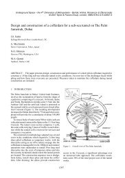
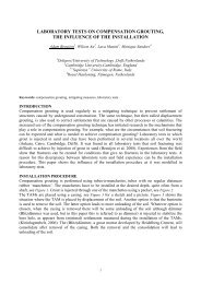
5.7km. In order to avoid underp<strong>in</strong>n<strong>in</strong>g of <strong>the</strong> residential houses and high-rise residential flats, <strong>the</strong> tw<strong>in</strong><br />
bored tunnels have to be aligned at very close distance of less than one tunnel diameter. The tunnels at<br />
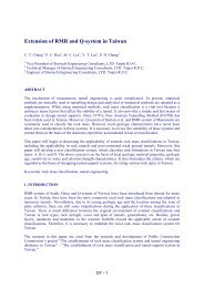
Lorong Gambir are <strong>the</strong> closest with a m<strong>in</strong>imum clearance of 2.3m, see Figure 1.<br />
Serangoon Ave. 1<br />
St. Gambriel’s<br />
Secondary<br />
School<br />
M<strong>in</strong>imum clearance<br />
between tunnels: 2.3m<br />
Gambir Walk<br />
To Serangoon station<br />
Figure 1. Tunnels at Lorong Gambir<br />
F19 1
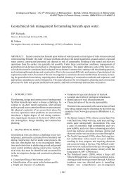
Figure 2 shows <strong>the</strong> general arrangement of <strong>the</strong> segments. The pre-cast re<strong>in</strong>forced concrete segmental<br />
l<strong>in</strong><strong>in</strong>gs are designed by <strong>the</strong> LTA <strong>in</strong>-house team. The <strong>in</strong>ternal diameter of <strong>the</strong> tunnels is 5.8 metres<br />
def<strong>in</strong>ed by space requirements. The thickness of <strong>the</strong> l<strong>in</strong><strong>in</strong>g is designed to be 275mm. A segment length<br />
of 1.4m is adopted. Each r<strong>in</strong>g consists of five ord<strong>in</strong>ary segments plus a key segment. Curved bolts are<br />
designed for both <strong>the</strong> radial and circumferential jo<strong>in</strong>ts. A composite hydrophilic and elastomeric<br />
gasket is specified on <strong>the</strong> draw<strong>in</strong>g. The r<strong>in</strong>gs have a maximum taper of 40mm. The radial jo<strong>in</strong>ts are<br />
convex to convex jo<strong>in</strong>ts. This type of jo<strong>in</strong>ts allows some articulation to take place. Because <strong>the</strong> radial<br />
jo<strong>in</strong>ts are staggered from r<strong>in</strong>g to r<strong>in</strong>g, <strong>the</strong> l<strong>in</strong><strong>in</strong>g is considered <strong>in</strong> <strong>the</strong> normal load comb<strong>in</strong>ations as a<br />
cont<strong>in</strong>uous r<strong>in</strong>g. The circumferential jo<strong>in</strong>ts are flat jo<strong>in</strong>ts.<br />
Figure 2. General arrangement of tunnel segments<br />
The concrete for <strong>the</strong> segments is specified to be grade 60 concrete with a 28-day compressive strength<br />
of 60 N/mm 2 . Silica fume is required <strong>in</strong> <strong>the</strong> concrete mix under <strong>the</strong> contract to reduce <strong>the</strong> permeability<br />
and <strong>the</strong> chlorite diffusion rate of <strong>the</strong> segments. The extrados of <strong>the</strong> segments is also required to be<br />
coated with epoxy.<br />
2. DESIGN OF REINFORCED CONCRETE SEGMENTAL LINING<br />
2.1 Design concept<br />
It has been well established that tunnel l<strong>in</strong><strong>in</strong>g <strong>in</strong> soft ground will redistribute <strong>the</strong> ground load<strong>in</strong>g. The<br />
ground load<strong>in</strong>g act<strong>in</strong>g on a circular tunnel l<strong>in</strong><strong>in</strong>g can be divided <strong>in</strong>to two components: <strong>the</strong> uniform<br />
distributed radial component and <strong>the</strong> distortional component. The uniform distributed radial<br />
component will only produce hoop thrust and <strong>the</strong> l<strong>in</strong><strong>in</strong>g will deform <strong>in</strong> <strong>the</strong> radial direction with <strong>the</strong><br />
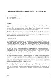
shape of <strong>the</strong> r<strong>in</strong>g rema<strong>in</strong><strong>in</strong>g circular. The distortional component will produce bend<strong>in</strong>g moments <strong>in</strong> <strong>the</strong><br />
l<strong>in</strong><strong>in</strong>g, and <strong>the</strong> crown and <strong>in</strong>vert will be squatted (move <strong>in</strong>wards) and at <strong>the</strong> axial level <strong>the</strong> l<strong>in</strong><strong>in</strong>g will<br />
move outwards, Figure 3. The soil pressure at <strong>the</strong> crown and <strong>in</strong>vert will be reduced as a result of <strong>the</strong><br />
<strong>in</strong>ward movement and <strong>the</strong> soil pressure at <strong>the</strong> axial level will be <strong>in</strong>creased due to <strong>the</strong> outward<br />
movement of <strong>the</strong> l<strong>in</strong><strong>in</strong>g. The redistribution of ground pressure around <strong>the</strong> r<strong>in</strong>g and <strong>the</strong> l<strong>in</strong><strong>in</strong>g<br />
de<strong>format</strong>ion will cont<strong>in</strong>ue until a balance is achieved. The stability of <strong>the</strong> tunnel l<strong>in</strong>ed by concrete<br />
segments thus depends on a cont<strong>in</strong>uous support / pressure around r<strong>in</strong>g. Any cavity <strong>in</strong> <strong>the</strong> space<br />
between <strong>the</strong> tunnel l<strong>in</strong><strong>in</strong>g and <strong>the</strong> ground will result <strong>in</strong> excessive distortional load<strong>in</strong>g on <strong>the</strong> l<strong>in</strong><strong>in</strong>g and<br />
may subject <strong>the</strong> r<strong>in</strong>g to undergo excessive distortion, caus<strong>in</strong>g unacceptable crack<strong>in</strong>g of <strong>the</strong> segments.<br />
F19 2
Deformed r<strong>in</strong>g<br />
Deformed<br />
r<strong>in</strong>g<br />
Figure 3. Tunnel l<strong>in</strong><strong>in</strong>g subjected to uniform distributed load<strong>in</strong>g and distortional load<strong>in</strong>g<br />
Various design methods are available for segmental l<strong>in</strong><strong>in</strong>g design. The Design Criteria of <strong>the</strong> Land<br />
Transport Authority (LTA) of S<strong>in</strong>gapore accept <strong>the</strong> methods of cont<strong>in</strong>uum model by Muir Wood<br />
(1975) modified by Curtis (1976), bedded beam model by Duddeck et al (1982) or <strong>the</strong> f<strong>in</strong>ite element<br />
method. The l<strong>in</strong><strong>in</strong>g for <strong>the</strong> CCL3 bored tunnel is designed us<strong>in</strong>g <strong>the</strong> cont<strong>in</strong>uum model. The method<br />
assumes that <strong>the</strong> l<strong>in</strong><strong>in</strong>g deforms <strong>in</strong> an elliptical shape and <strong>the</strong> ground is an elastic cont<strong>in</strong>uum. The hoop<br />
thrust and moment <strong>in</strong>duced by <strong>the</strong> soil-structure <strong>in</strong>teraction are evaluated accord<strong>in</strong>gly.<br />
2.2 Design analyses<br />
The tunnels are to be constructed through soft ground with a tunnel bor<strong>in</strong>g mach<strong>in</strong>e (TBM). The<br />
vertical pressure applied to <strong>the</strong> l<strong>in</strong><strong>in</strong>g is thus <strong>the</strong> full overburden pressure. Distortional load<strong>in</strong>g is<br />
derived by us<strong>in</strong>g <strong>the</strong> appropriate K-factor <strong>in</strong> Curtis formulae accord<strong>in</strong>g to <strong>the</strong> soil condition at <strong>the</strong><br />
tunnel location. The follow<strong>in</strong>g K-factors are used <strong>in</strong> accordance with <strong>the</strong> LTA Design Criteria:<br />
Table 1. K-factor<br />
Soil Type<br />
K<br />
Estuar<strong>in</strong>e, Mar<strong>in</strong>e and Fluvial Clays 0.75<br />
Beach Sands, Old Alluvium, Completely Wea<strong>the</strong>red Granite, Fluvial Sands 0.5<br />
Completely Wea<strong>the</strong>red Sedimentary Rocks 0.4<br />
Moderately to Highly Wea<strong>the</strong>red Sedimentary or Granite Rocks 0.3<br />
A uniform surcharge of 75 kN/m 2 is considered <strong>in</strong> <strong>the</strong> design. The design ground water table is taken<br />
at both <strong>the</strong> ground surface (upper limit) and 3m (lower limit) below <strong>the</strong> surface.<br />
The design assumes that <strong>the</strong> segments <strong>in</strong> <strong>the</strong> permanent condition are short columns subject to<br />
comb<strong>in</strong>ed hoop thrust and bend<strong>in</strong>g moment. Both ultimate limit state (ULS) and serviceability limit<br />
state (SLS) are checked. Ultimate limit state design ensures that <strong>the</strong> load bear<strong>in</strong>g capacity of <strong>the</strong> l<strong>in</strong><strong>in</strong>g<br />
is not exceeded while serviceability limit state design checks both <strong>the</strong> crack-width and de<strong>format</strong>ion of<br />
<strong>the</strong> l<strong>in</strong><strong>in</strong>g. The follow<strong>in</strong>g factors are used <strong>in</strong> <strong>the</strong> limit state design:<br />
• Ultimate limit state: Load factor for overburden and water pressure = 1.4<br />
Load factor for surcharge = 1.6<br />
F19 3
• Serviceability limit state: Load factor for overburden, surcharge and water pressure = 1.0<br />
The overburden, surcharge and water pressure are assumed as loads on <strong>the</strong> tunnel, and <strong>the</strong> effects of<br />
ground arch<strong>in</strong>g around <strong>the</strong> tunnel are neglected for tunnels <strong>in</strong> soft ground. For re<strong>in</strong>forcement design<br />
for both <strong>the</strong> ULS and SLS, <strong>the</strong> thrust and moment are obta<strong>in</strong>ed assum<strong>in</strong>g a cont<strong>in</strong>uous l<strong>in</strong><strong>in</strong>g with full<br />
section moment of <strong>in</strong>ertia and short-term Young's modulus for <strong>the</strong> concrete. This is to obta<strong>in</strong> <strong>the</strong><br />
maximum moment <strong>in</strong> <strong>the</strong> r<strong>in</strong>g. For deflection check<strong>in</strong>g <strong>the</strong> Young's modulus of <strong>the</strong> concrete is<br />
reduced by 50% to account for concrete creep. The moment of <strong>in</strong>ertia of <strong>the</strong> segment is also reduced<br />
based on <strong>the</strong> recommendation by Muir Wood (1975) that:<br />
I = I j +I f (4/n) 2<br />
where I j is <strong>the</strong> moment of <strong>in</strong>ertia of <strong>the</strong> jo<strong>in</strong>t (I j = 0), n is <strong>the</strong> total number of segments <strong>in</strong> a r<strong>in</strong>g and I f<br />
is <strong>the</strong> full moment of <strong>in</strong>ertia before reduction. This is to obta<strong>in</strong> <strong>the</strong> maximum deflection <strong>in</strong> <strong>the</strong> r<strong>in</strong>g.<br />
The design analyses have been carried out for sections where <strong>the</strong> tunnels are expected to experience a<br />
maximum and m<strong>in</strong>imum overburden pressure and where <strong>the</strong> tunnels transverses different soil strata.<br />
The load comb<strong>in</strong>ations are listed <strong>in</strong> Table 2.<br />
Table 2. Load comb<strong>in</strong>ations<br />
LOAD<br />
COMBINATIONS<br />
Load Factor = 1.4<br />
and 1.6<br />
ULS<br />
SLS<br />
(crack width)<br />
SLS<br />
(deflection)<br />
1 2 3 4 5 6 7 8 9 10 11 12<br />
√ √ √ √ √<br />
Load Factor = 1.0 √ √ √ √ √ √ √<br />
75kN/m 2 Uniform<br />
Surcharge<br />
Water Table at<br />
Ground Surface<br />
Water Table 3m<br />
Below Ground<br />
Surface<br />
<strong>Full</strong> Section Moment<br />
of Inertia<br />
Reduced Section<br />
Moment of Inertia<br />
Short Term Concrete<br />
Young's Modulus<br />
Long Term Concrete<br />
Young's Modulus<br />
Additional Distortion<br />
of 15mm on<br />
Diameter<br />
√ √ √ √ √ √ √ √<br />
√ √ √ √ √<br />
√ √ √ √ √ √ √<br />
√ √ √ √ √ √ √ √<br />
√ √ √ √<br />
√ √ √ √ √ √ √ √<br />
√ √ √ √<br />
√<br />
√<br />
F19 4
2.3 Effect of <strong>the</strong> second tunnel construction on <strong>the</strong> first tunnel<br />
Typically for tw<strong>in</strong> bored tunnels, <strong>the</strong> second tunnel drive will be some distance beh<strong>in</strong>d <strong>the</strong> first tunnel<br />
drive. If <strong>the</strong>re is adequate clearance between <strong>the</strong> two tunnels, <strong>the</strong> effect of <strong>the</strong> second tunnel<br />
construction on <strong>the</strong> erected segmental l<strong>in</strong><strong>in</strong>g of <strong>the</strong> first tunnel is negligible. The rule of thumb is that<br />
<strong>the</strong> clearance between <strong>the</strong> two tunnels should not be less than one tunnel diameter. If <strong>the</strong> clearance<br />
between <strong>the</strong> tunnels is less than one tunnel diameter, <strong>the</strong> design should make allowance <strong>in</strong> <strong>the</strong> l<strong>in</strong><strong>in</strong>g of<br />
<strong>the</strong> first tunnel for <strong>the</strong> effect of <strong>the</strong> second tunnel construction.<br />
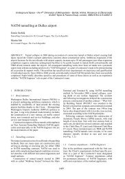
Ground movement due to <strong>the</strong> second tunnel construction will cause additional movements to <strong>the</strong> first<br />
tunnel besides that due to <strong>the</strong> ground load<strong>in</strong>g. The additional movements will result <strong>in</strong> additional<br />
distortion, which is <strong>the</strong> difference of <strong>the</strong> movements of <strong>the</strong> first tunnel at two diametrically opposite<br />
po<strong>in</strong>ts, such as at po<strong>in</strong>ts a and b, where po<strong>in</strong>t a is closest to and po<strong>in</strong>t b is <strong>the</strong> fur<strong>the</strong>st from <strong>the</strong> second<br />
tunnel, see Figure 4. Correspond<strong>in</strong>gly <strong>the</strong>re will also be an additional distortion between <strong>the</strong> crown<br />
and <strong>in</strong>vert of <strong>the</strong> tunnel. For design purpose, it is necessary to establish <strong>the</strong> maximum additional<br />
distortion to compute <strong>the</strong> maximum additional moment that <strong>the</strong> l<strong>in</strong><strong>in</strong>g will be subjected to. The<br />
maximum distortion will take place across <strong>the</strong> diameter along <strong>the</strong> l<strong>in</strong>e connected by <strong>the</strong> centres of <strong>the</strong><br />
two tunnels, i.e. po<strong>in</strong>ts a and b <strong>in</strong> Figure 4. This maximum distortion can be calculated based on <strong>the</strong><br />
<strong>the</strong>ory of elasticity by us<strong>in</strong>g <strong>the</strong> volume loss due to <strong>the</strong> construction of <strong>the</strong> second tunnel.<br />
y<br />
p<br />
Second<br />
tunnel<br />
r o<br />
x<br />
a<br />
First<br />
tunnel<br />
b<br />
Figure 4. Two tunnels at close proximity<br />
Assum<strong>in</strong>g that <strong>the</strong> ground is a homogeneous, isotropic, l<strong>in</strong>early elastic mass, <strong>the</strong> radial movement of<br />
<strong>the</strong> ground at a radial distance r from <strong>the</strong> centre of <strong>the</strong> second tunnel can be derived based on <strong>the</strong><br />
<strong>the</strong>ory of elasticity as follows:<br />
u = u o r o /r (1)<br />
The volume loss dur<strong>in</strong>g tunnell<strong>in</strong>g can be expressed as:<br />
Vs = {πr o 2 - π( r o - u o ) 2 }/ πr o<br />
2<br />
(2)<br />
Equation (2) gives:<br />
u o = r o {1-√(1-Vs)} (3)<br />
F19 5
Us<strong>in</strong>g equation (1) and (3):<br />
At po<strong>in</strong>t a, u a = u o r o /r a , where r a is <strong>the</strong> distance of po<strong>in</strong>t a to <strong>the</strong> centre of <strong>the</strong> second tunnel.<br />
At po<strong>in</strong>t b, u b = u o r o /r b , where r a is <strong>the</strong> distance of po<strong>in</strong>t a to <strong>the</strong> centre of <strong>the</strong> second tunnel.<br />
The maximum diametrical distortion, δ d is def<strong>in</strong>ed as δ d = u a - u b<br />
The radial distortion is given by:<br />
δ r = δ d /2 (4)<br />
Morgan (1961) showed that <strong>the</strong> bend<strong>in</strong>g moment due to distortion over radius is given by:<br />
M = (3EIδ r )/ r o<br />
2<br />
(5)<br />
Based on equations (4) and (5), <strong>the</strong> additional distortional moment <strong>in</strong> <strong>the</strong> first tunnel l<strong>in</strong><strong>in</strong>g due to <strong>the</strong><br />
second tunnel construction can be calculated. The total bend<strong>in</strong>g moments for structural design of <strong>the</strong><br />
segments are superimposed by add<strong>in</strong>g <strong>the</strong> additional distortional moment to <strong>the</strong> moment due to ground<br />
load<strong>in</strong>g, assum<strong>in</strong>g <strong>the</strong> hoop thrust rema<strong>in</strong>s unchanged.<br />
3. ALLOWABLE ADDITIONAL DISTORTION FOR CONSTRUCTION<br />
The method outl<strong>in</strong>ed <strong>in</strong> Section 2.3 above can be used to make allowance <strong>in</strong> <strong>the</strong> design of <strong>the</strong> tunnel<br />
l<strong>in</strong><strong>in</strong>g to cater for <strong>the</strong> effect of <strong>the</strong> second tunnel construction on <strong>the</strong> first tunnel. However, it is<br />
difficult to monitor such effect dur<strong>in</strong>g construction as <strong>the</strong> method relies on <strong>the</strong> prompt assessment of<br />
<strong>the</strong> volume loss generated by <strong>the</strong> second tunnel construction. This back analysis of <strong>the</strong> volume loss is<br />
typically not readily available at <strong>the</strong> time of tunnel construction. It is thus not practicable to use<br />
volume loss as a controll<strong>in</strong>g parameter dur<strong>in</strong>g construction. In order to overcome this shortcom<strong>in</strong>g, it<br />
is proposed to use <strong>the</strong> conventional convergence monitor<strong>in</strong>g as a means to ensure that <strong>the</strong> additional<br />
distortion of <strong>the</strong> first tunnel due to <strong>the</strong> second tunnel construction is with<strong>in</strong> <strong>the</strong> capacity of <strong>the</strong> l<strong>in</strong><strong>in</strong>g of<br />
<strong>the</strong> first tunnel.<br />
Additional analyses have been carried out <strong>in</strong> <strong>the</strong> design of CCL3 tunnel l<strong>in</strong><strong>in</strong>g to determ<strong>in</strong>e <strong>the</strong><br />
allowable additional diametrical distortion for construction. This allowable diametrical distortion is<br />
not only for <strong>the</strong> effect of second tunnel construction, but also for <strong>the</strong> effects of all o<strong>the</strong>r construction<br />
activities, for example cross passage construction. In <strong>the</strong> analyses, it has been assumed that <strong>the</strong> r<strong>in</strong>g<br />
has a reduced moment of <strong>in</strong>ertia as recommended by Muir Wood (1975). The follow<strong>in</strong>g steps are<br />
taken to determ<strong>in</strong>e <strong>the</strong> allowable diametrical distortion for construction:<br />
• The hoop thrust and moment under <strong>the</strong> ground load<strong>in</strong>g and surcharge are calculated based on <strong>the</strong><br />
method described by Muir Wood (1975) and modified by Curtis (1976);<br />
• The spare moment capacity is taken as <strong>the</strong> difference between <strong>the</strong> ultimate capacity based on <strong>the</strong><br />
re<strong>in</strong>forcement provided and <strong>the</strong> calculated moment due to <strong>the</strong> ground load<strong>in</strong>g and surcharge. Both<br />
ULS and SLS are checked and <strong>the</strong> lesser of <strong>the</strong> two is taken as <strong>the</strong> spare moment capacity that <strong>the</strong><br />
r<strong>in</strong>g has for construction.<br />
• This spare moment capacity is converted <strong>in</strong>to radial distortion with <strong>the</strong> use of Equation (10). This<br />
distortion multiplied by two is thus <strong>the</strong> allowable diametrical distortion for construction.<br />
Assum<strong>in</strong>g <strong>the</strong> allowable diametrical distortion will be fully developed dur<strong>in</strong>g construction, <strong>the</strong> r<strong>in</strong>g is<br />
checked for <strong>the</strong> capacity of 15mm distortion allowed for long term due to adjacent future unknown<br />
F19 6
development. Aga<strong>in</strong>, <strong>the</strong> additional moment that will be generated <strong>in</strong> <strong>the</strong> l<strong>in</strong><strong>in</strong>g due to <strong>the</strong> 15mm<br />
diametric distortion is computed by us<strong>in</strong>g Equation (10).<br />
The above procedures are illustrated by <strong>the</strong> N-M <strong>in</strong>teraction diagram <strong>in</strong> Figure 5 for <strong>the</strong> ultimate limit<br />
state. For serviceability limit state (crack width check<strong>in</strong>g), similar approach can be adopted.<br />
10000<br />
N (kN)<br />
9000<br />
8000<br />
7000<br />
6000<br />
5000<br />
4000<br />
3000<br />
2000<br />
1000<br />
0<br />
Ground<br />
Load<strong>in</strong>g<br />
Spare<br />
Capacity<br />
0 50 100 150 200 250 300 350 400<br />
M (kNm)<br />
f cu = 60 N/mm 2<br />
h = 275 mm<br />
b = 1000 mm<br />
Ground Load<strong>in</strong>g<br />
Ground Load<strong>in</strong>g +1%<br />
Volume Loss<br />
Figure 5. Moment – Hoop Thrust <strong>in</strong>teraction diagram for re<strong>in</strong>forcement ratio of 1.19%.<br />
4. MONITORING REQUIREMENTS<br />
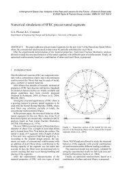
The proposed monitor<strong>in</strong>g scheme is shown <strong>in</strong> Figure 6. The convergence monitor<strong>in</strong>g can be made by<br />
extensometers and <strong>the</strong> measurement should be able to determ<strong>in</strong>e <strong>the</strong> diametrical distortion of <strong>the</strong><br />
l<strong>in</strong><strong>in</strong>g. The required monitor<strong>in</strong>g frequency for each r<strong>in</strong>g <strong>in</strong> <strong>the</strong> first tunnel will depend on <strong>the</strong> position<br />
of <strong>the</strong> TBM of <strong>the</strong> second tunnel.<br />
Direction of advance<br />
TBM<br />
2nd Tunnel<br />
1st Tunnel<br />
1 D 1 D L 1 D 3 D<br />
Once daily<br />
Every 6 hours or every r<strong>in</strong>g<br />
progress whichever is<br />
Once daily<br />
Legend: L = length of TBM shield, D = Excavated tunnel diameter<br />
Figure 6. Convergence monitor<strong>in</strong>g scheme with read<strong>in</strong>g frequency<br />
F19 7
5. CONCLUSIONS<br />
The design methodology is presented for <strong>the</strong> design of <strong>the</strong> tunnel l<strong>in</strong><strong>in</strong>gs for CCL3 bored tunnels. A<br />
method has been proposed to make allowance <strong>in</strong> <strong>the</strong> tunnel l<strong>in</strong><strong>in</strong>g design to cater for <strong>the</strong> effect of <strong>the</strong><br />
second tunnel construction on <strong>the</strong> first tunnel if <strong>the</strong> two tunnels are aligned at closer than one tunnel<br />
diameter apart. Procedures are developed to derive <strong>the</strong> additional distortional capacity of tunnel<br />
l<strong>in</strong><strong>in</strong>gs. This capacity can be monitored dur<strong>in</strong>g construction by <strong>the</strong> conventional tunnel convergence<br />
monitor<strong>in</strong>g us<strong>in</strong>g taper extensometers. As <strong>the</strong> monitor<strong>in</strong>g is relatively simple and fast, <strong>the</strong> results will<br />
enable <strong>the</strong> eng<strong>in</strong>eer to assess whe<strong>the</strong>r <strong>the</strong> capacity of <strong>the</strong> l<strong>in</strong><strong>in</strong>g is exceeded dur<strong>in</strong>g construction.<br />
6. REFERENCES<br />
Curtis, D.J., 1976. Discussion, Geotechnique 26, 231 – 237<br />
Duddeck, H. and Erdmann, J., 1982. Structural design models for tunnels, Tunnell<strong>in</strong>g’82, International<br />
Symposium organised by Institution of M<strong>in</strong><strong>in</strong>g and Metallurgy.<br />
Morgan, H.D., 1961. A contribution to <strong>the</strong> analysis of stress <strong>in</strong> a circular tunnel, Geotechnique 11, 37<br />
– 46<br />
Muir Wood, A.M., 1975. The circular tunnel <strong>in</strong> elastic ground, Geotechnique 25, No. 1, 115 – 127.<br />
F19 8