Gahir, J.S.
Gahir, J.S.
Gahir, J.S.

You also want an ePaper? Increase the reach of your titles
YUMPU automatically turns print PDFs into web optimized ePapers that Google loves.
Underground Space – the 4 th Dimension of Metropolises – Barták, Hrdina, Romancov & Zlámal (eds)<br />
© 2007 Taylor & Francis Group, London, ISBN 978-0-415-40807-3<br />
Design and construction of a cofferdam for a sub-sea tunnel on The Palm<br />
Jumeirah, Dubai<br />
J.S. <strong>Gahir</strong><br />
Kellogg Brown & Root, Leatherhead, UK<br />
A. Mochizuki<br />
Taisei Corporation, Tokyo, Japan<br />
N.O. Othman<br />
Parsons PTG, Washington, USA<br />
M.A. Qamzi<br />
Nakheel, Dubai, UAE<br />
ABSTRACT: The paper presents design, construction and performance of a sheet piled cofferdam required to<br />
construct a 1.4 km long sub-sea vehicular tunnel in dry conditions. An overview of the challenges faced whilst<br />
piling and how these were overcome are presented. Measures taken to maintain the cofferdam during tunnel<br />
construction are included.<br />
1 INTRODUCTION<br />
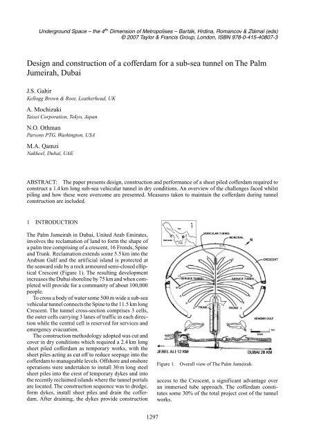
The Palm Jumeirah in Dubai, United Arab Emirates,<br />
involves the reclamation of land to form the shape of<br />
a palm tree comprising of a crescent, 16 Fronds, Spine<br />
and Trunk. Reclamation extends some 5.5 km into the<br />
Arabian Gulf and the artificial island is protected at<br />
the seaward side by a rock armoured semi-closed elliptical<br />
Crescent (Figure 1). The resulting development<br />
increases the Dubai shoreline by 75 km and when completed<br />
will provide for a community of about 100,000<br />
people.<br />
To cross a body of water some 500 m wide a sub-sea<br />
vehicular tunnel connects the Spine to the 11.5 km long<br />
Crescent. The tunnel cross-section comprises 3 cells,<br />
the outer cells carrying 3 lanes of traffic in each direction<br />
while the central cell is reserved for services and<br />
emergency evacuation.<br />
The construction methodology adopted was cut and<br />
cover in dry conditions which required a 2.4 km long<br />
sheet piled cofferdam as temporary works, with the<br />
sheet piles acting as cut off to reduce seepage into the<br />
cofferdam to manageable levels. Offshore and onshore<br />
operations were undertaken to install 30 m long steel<br />
sheet piles into the crest of temporary dykes and into<br />
the recently reclaimed islands where the tunnel portals<br />
are located. The construction sequence was to dredge,<br />
form dykes, install sheet piles and drain the cofferdam.<br />
After draining, the dykes provide construction<br />
Figure 1.<br />
Overall view of The Palm Jumeirah.<br />
access to the Crescent, a significant advantage over<br />
an immersed tube approach. The cofferdam constitutes<br />
some 30% of the total project cost of the tunnel<br />
works.<br />
1297
Figure 2.<br />
Tunnel alignments.<br />
Figure 3.<br />
Typical cross section and ground conditions.<br />
2 PROJECT DESCRIPTION<br />
The total length of the tunnel structure is 1398 m and<br />
comprises of a 241 m long Spine portal approach,<br />
969 m of reinforced concrete box section and 188 m<br />
of Crescent portal approach.<br />
The horizontal and vertical alignments were dictated<br />
by a maximum grade of 6% for a 60 kph design<br />
speed, in compliance with Dubai Municipality Geometric<br />
Design Manual for Dubai Roads (1999), and the<br />
need to ensure that the tunnel was sufficiently deep to<br />
maintain a 125 m wide arc-shaped navigation channel<br />
with a minimum draft of 10 m, above the 1.5 m thick<br />
layer of armour protection on the roof slab. The vertical<br />
alignment and the horizontal alignment, which is a<br />
reverse curve with a central straight section, are shown<br />
in Figure 2.<br />
Mean sea level is +1.0 mDMD (Dubai Municipality<br />
Datum, which is 0.09 m below Admiralty Chart<br />
Datum) with a tidal range of 1.2 m between MHHW<br />
and MLLW. The reclaimed islands are at +3 m and<br />
+4 mDMD at the Spine and Crescent, respectively.<br />
Seabed elevations before The Palm reclamation were<br />
in the range −11 m to −12 mDMD. Pre-construction<br />
surveys indicated that the minimum seabed elevation<br />
along the tunnel alignment and the cofferdam<br />
region was −15 m and −19 mDMD respectively, in<br />
areas where materials had been won for breakwater<br />
construction.<br />
A Design and Build contract was awarded to Taisei<br />
Corporation in 2004 for the construction of the<br />
vehicular tunnel.<br />
3 GEOLOGY AND GROUND CONDITIONS<br />
The local geology in the vicinity of the project site<br />
has been shaped by the current hot arid climate and<br />
by fluctuations in sea level and is described by <strong>Gahir</strong><br />
et al. (2006).<br />
Ground conditions were determined by sinking 13<br />
offshore boreholes to a depth of 30 m into the seabed<br />
and 3 boreholes up to 30 m depth on the onshore<br />
reclamation. The minimum elevation explored is<br />
−45 mDMD. The offshore boreholes were drilled<br />
along the alignment of the dykes and are offset up to<br />
230 m from the tunnel centre line. All boreholes were<br />
grouted after completion.<br />
The boreholes revealed that under a 12 m thick<br />
recent fill a 1 m to 2 m thick band of weak caprock<br />
is present which in turn is underlain by 2 m to 4 m<br />
thick layer of medium dense sand. The sand overlies<br />
an 18 m to 22 m thick sequence of very weak to weak<br />
interbedded calcarenite and sandstone. A conglomerate<br />
layer whose upper horizon is some −35 mDMD is<br />
present across the site (Figure 3). The UCS of rock<br />
encountered is in the range 1 to 3.5 MPa. In isolated<br />
boreholes a thin layer of soft silt was recorded<br />
1298
under the fill, and is suspected to be the original<br />
seabed.<br />
In-situ permeability of the rock units, measured<br />
using standard Lugeon tests and variable head permeability<br />
tests, indicated k values ranging from<br />
4×10 −6 to 5×10 −4 m/sec with lower values at depth.<br />
4 DESIGN CONSIDERATIONS<br />
The cofferdam is required for some 17 months and at<br />
peak periods a workforce of about 1000 was expected<br />
within its confines and thus safety was of paramount<br />
consideration in the design process.<br />
The cofferdam outline was dictated by the following<br />
considerations (a) the dykes have a 12 m wide crest at<br />
−2 mDMD; an elevation adopted after a soil-structure<br />
interaction analysis was undertaken for different pile<br />
sections and various crest elevations, to provide a<br />
balance between the fill available and the structural<br />
performance of the piles (b) the sheet piles were<br />
planned 2 m from the seaward edge so that a 10 m<br />
wide corridor was available for a 2 lane temporary<br />
road inside the cofferdam after draining (c) the tunnel<br />
trench at its deepest is −26 mDMD and the trench<br />
slopes, located in interbedded sandstone and calcarenite,<br />
were planned at 1V:0.5 H (d) a 15 m minimum<br />
clearance was maintained from the top of the trench<br />
excavation to the toe of the dyke thus avoiding surcharging<br />
and undermining the stability of the trench<br />
slope and (e) a dyke slope of 1V:4 H from crest to<br />
−10 mDMD and 1V:7 H thereafter, was adopted from<br />
slope stability considerations based on recent experience<br />
gained in the construction of The Palm. A 2.4 km<br />
long cofferdam outline was thus identified having a<br />
plan area of some 300,000 m 2 and a maximum width<br />
of about 400 m. This outline involved 1550 m of offshore<br />
piles and 850 m of onshore piles. Local filling<br />
adjacent to the recently formed islands was undertaken<br />
to maximize land based operations.<br />
Both marine and land driven sheet piles are up to<br />
30 m long and the top of the piles were planned at<br />
+3.3 mDMD for minimal overtopping under storm<br />
surge and wave conditions, and the toe at −26 mDMD<br />
based on seepage analyses which required 1 m minimum<br />
penetration into the lower less permeable sandstone<br />
which underlies the calcarenite. Bending stresses<br />
and deflections complying with Technical Standard<br />
and Commentary for Port and Harbour Facilities<br />
(2001) indicated that pile sections SX27 (section modulus,<br />
z = 2700 cm 3 /m) for the offshore piles, and PU25<br />
(z = 2500 cm 3 /m) for onshore piles were appropriate.<br />
The estimated maximum deflections at the top<br />
of the marine piles, after draining, was calculated to<br />
be about 200 mm and the relative deflection between<br />
+3 m and −2 mDMD i.e. the cantilevered section, to<br />
be about 150 mm. These estimates are based on a<br />
sea level of +2.45 mDMD, to take account of storm<br />
surge, and a horizontal modulus of subgrade reaction<br />
of 10,000 KN/m 2 /m based on an empirical relationship<br />
to an SPT-N value of 5.<br />
Seepage analysis using 2D FLOW with an average<br />
k value determined for each substrata indicated that<br />
some 820 m 3 /hr could be expected under the cofferdam<br />
once steady state conditions had established.<br />
French drains at the base of the tunnel trench, with<br />
pits and submersible pumps of sufficient capacity, and<br />
lines of well point systems were designed to collect the<br />
inflow (Figure 4). The collected inflow was directed<br />
to two locations, one either side of the tunnel trench,<br />
before being pumped back to the sea over each dyke<br />
with due care taken not to erode the outer slope.<br />
5 CONSTRUCTION METHODOLOGY<br />
5.1 Dyke construction<br />
Cutter suction dredgers were used to excavate the tunnel<br />
trench, one for shallow and one for deep dredging<br />
below −15 mDMD, with operations commencing at<br />
the end of the alignment i.e. at the newly formed<br />
islands and progressing towards the centre where the<br />
trench is deepest.The dredgers lowered the seabed elevation<br />
by some 2 m in a single step until the desired elevation<br />
along the tunnel alignment was achieved within<br />
0.5 m of the invert elevation, with the final grade being<br />
achieved using earthworks equipment in dry conditions.<br />
Seabed elevations were constantly monitored<br />
by surveying equipment on the dredger and from a<br />
survey boat.<br />
The dredged material was sucked into the dredger<br />
holds and placed at the dyke locations using a spread<br />
pontoon positioned by GPS and controlled by anchors<br />
and winches. Both dykes were built up concurrently<br />
and care was required to achieve the 1V:4 H<br />
slope by considerably reducing the volume discharged<br />
through the pipe. Total volume for the two dykes<br />
was 920,000 m 3 of which 660,000 m 3 was obtained<br />
from the tunnel trench excavation and the balance<br />
was obtained from a borrow source nearby, with a<br />
small quantity purchased from a supplier. A larger<br />
volume than had been estimated at the tender stage<br />
was necessary due to the flattening of the dyke slopes<br />
from 1V:4 H to 1V:7 H below −10 mDMD as already<br />
described in Section 4. Bathymetric surveys were carried<br />
out after filling to either confirm that the desired<br />
dyke profile had been achieved or identify local areas<br />
requiring additional fill.<br />
5.2 Sheet pile procurement and preparation<br />
Procurement of the 12,500T of sheet piles was a lead<br />
item due to a shortage on the world market. Some<br />
9500T of new SX27 sections in 15 m lengths were<br />
1299
MAX. DSP=130mm<br />
MAX. DD=4.9mm<br />
WLD -15.9DMD<br />
CRESCENT<br />
NW<br />
SW<br />
SE<br />
MAX. DSP<br />
MAX. DD<br />
WLD<br />
Figure 4.<br />
Dewatering regime and cofferdam monitoring points.<br />
procured from Japan and had a2to3month delivery<br />
time. Used PU25 sections of some 10 m length were<br />
purchased locally and taken to an onsite yard at the top<br />
of the Spine where 20 m lengths were assembled. To<br />
determine the sheet pile drivability a trial was undertaken<br />
near the Spine portal close to a borehole location<br />
using PU series. The piles were spliced and driven to<br />
depths of 33 m using vibrohammer ICE815C (1250 kN<br />
max centrifugal force) without difficulty.<br />
The newly purchased SX27 sections were taken to<br />
Hamriya Port, about 35 km east of the project site,<br />
where they were chamfered and welded to form 30 m<br />
lengths. Hyperseal DPS-1000 was applied to the pile<br />
clutch. This material can expand up to 10 times its<br />
original volume in fresh water but its performance offshore<br />
is curtailed due to the salinity of sea water and<br />
it expands to half the figure. The piles were paired to<br />
form 1.2 m wide panels, so that each prepared offshore<br />
panel comprised of 4 sheet piles, before being barged<br />
to site.<br />
5.3 Onshore sheet piling<br />
Sheet pile sections, 20 m long and 0.6 m wide, were<br />
pitched into a guide frame capable of accommodating<br />
16 sheet piles and driven one by one with a 1.5 m stick<br />
up. Longer sheet piles could not be accommodated<br />
due to limitation of the crane boom. Ten metre long<br />
pile sections were hooked through the guide frame and<br />
spliced to the driven piles. Driving recommenced using<br />
vibrohammer ICE815C and progress was slow due to<br />
difficult driving. Some hard nodules present within the<br />
calcarenite and the wear and tear on the used piles were<br />
felt to contribute to difficult driving. Additionally two<br />
splices in the desired pile length did not always provide<br />
a plumb vertical section and this led to an increase in<br />
the frictional force in the pile clutch.<br />
At some locations especially on the Crescent piles<br />
were terminated 5m short of the required design penetration<br />
due to refusal with the driving system. A<br />
reassessment of the seepage inflow into the cofferdam<br />
was undertaken using k of calcarenite 2×10 −5 m/s<br />
which indicated that the anticipated inflow in this<br />
area increased 9 times locally with the nett effect that<br />
the overall infow into the cofferdam after draining<br />
increased from 820 m 3 /hr to 1600 m 3 /hr. To cope with<br />
the additional inflow contingency measures were put<br />
in place and comprised of (a) drive secondary short<br />
length sheet piles in local areas at the top of the tunnel<br />
trench excavation (b) increase the number of wells and<br />
(c) increase pump capacity.<br />
5.4 Offshore sheet piling<br />
Offshore piling was undertaken from 2 barges, each<br />
with a 150T crane, and the prepared panels 30 m long<br />
and 1.2 m wide, were driven through a guide frame<br />
using a double clutch vibrohammer ICE1412 (2300 kN<br />
max centrifugal force). The contractor reported difficult<br />
driving conditions which required greater effort<br />
1300
in getting the necessary penetration than had been<br />
anticipated initially. On average 2 to 3 panels were<br />
being achieved in a 12 hour shift. When the second<br />
barge, operating a week later on the opposite dyke,<br />
also experienced similar difficulties it was recognized<br />
that the problem was not local.<br />
Piling records indicated that the penetration rate<br />
decreased significantly below −17 mDMD in the second<br />
calcarenite layer. A review of the unconfined<br />
compressive strength results indicated weak rock and<br />
that although the presence of hard nodules may explain<br />
some of the driving difficulties, something fundamental<br />
had been overlooked. Pairing the piles doubled the<br />
area at the cutting edge and also doubled the friction<br />
from the fill and underlying rock, and this resistance<br />
could not be overcome by simply doubling the hammer<br />
capacity required for a single pile section.The decision<br />
to pair the piles was taken after discussion with a local<br />
piling contractor who had successfully driven paired<br />
piles but not to the depth required for this project. An<br />
offshore pile driving trial may have revealed the problem<br />
earlier, and more work in this area would have<br />
been useful.<br />
To overcome the difficulties in the short term predriving<br />
was undertaken with a panel connected to a<br />
water jetting system to −25 mDMD and withdrawn,<br />
and the final 1 m was driven with the permanent pile.<br />
Following the initial success with water jetting, a decision<br />
was taken to weld four 25 mm diameter steel pipes<br />
in the corners of all the sheet piles along its total<br />
length and connected to 2 mm diameter jetting nozzles<br />
located near the toe of the sheet pile. The pipes were<br />
hooked to a high pressure pump capable of delivering<br />
250 l/min at 40 bar pressure. Simultaneous water jetting<br />
and driving with the same hammer overcame the<br />
driving difficulties. To make up for lost time a third<br />
barge was mobilized and a night shift introduced. In<br />
86 working days 1290 paired sheet piles were successfully<br />
driven to the desired toe elevation. Towards the<br />
end a production rate of 5 to 6 pairs was being achieved<br />
in a single shift.<br />
5.5 Cofferdam closure<br />
Seven onshore and 2 offshore closures were necessary<br />
to complete the perimeter. Sheet pile sections driven<br />
from the opposite ends were overlapped so that an open<br />
box was formed. A uPVC tube was inserted from the<br />
top of the piles to key into the top of the dyke and<br />
grouted, thus sealing the open box. After setting, a<br />
borehole was drilled through the grout, the dyke and<br />
into seabed extending to the same elevation as the toe<br />
of the sheet piles. A rapid setting chemical grout, colloidal<br />
silica with sodium chloride, was then injected<br />
at 0.5 m centres working from the bottom up. The colloidal<br />
silica when set has a very low permeability, thus<br />
effectively sealing the closure point.<br />
The offshore closure was undertaken during a Neap<br />
tide within a 4 hour window. Due to an increased flow<br />
velocity some scouring of the dyke, up to 2 m deep over<br />
an 8 m long section, was observed by divers deployed<br />
periodically during the course of the works. The dyke<br />
was repaired after closure.<br />
5.6 Draining<br />
Some 4,350,000 m 3 of water inside the cofferdam<br />
(excluding seepage) was pumped out in stages to<br />
reduce the water level from +1mto−23 mDMD. This<br />
was undertaken using 9 high capacity pumps each fitted<br />
with a flow meter, of which 7 were operational at<br />
one time, connected via valves and manifolds to the<br />
discharge pipes and over the northern cofferdam wall<br />
and to sea. The pumps were located on two floating<br />
pontoons placed centrally at the deepest section of the<br />
trench excavation. Discharge was completed in 45 days<br />
and the rate of water level drop was maintained at less<br />
than 1 m/day. Some leaks in the sheet piles joints were<br />
sealed using underwater welding and sealants.<br />
6 IN-SERVICE PERFORMANCE AND<br />
MONITORING<br />
6.1 Summary of instrumentation installed<br />
To provide information on sheet pile deflections, the<br />
deformation of the dykes, and water levels in the cofferdam<br />
6 total station targets with a mirror attachment,<br />
8 inclinometers, 16 observation wells with ground<br />
water loggers, and settlement monitoring stations were<br />
installed at strategic locations and depths. Base readings<br />
were established on top of the sheet piles before<br />
draining and the instruments were installed shortly<br />
thereafter. Temporary bench marks were installed at<br />
50 m intervals on the shoulder of the dyke for monitoring<br />
settlements. Trigger and action values were<br />
identified for each item along with an action plan<br />
should the values be exceeded, and to provide an early<br />
warning system in the event that unanticipated conditions<br />
arise.Typical results are included on Figure 4 and<br />
an aerial view of the cofferdam is shown on Figure 5.<br />
6.2 Strengthening works<br />
A maximum total deflection of some 1000 mm and<br />
a relative deflection of 285 mm was recorded along<br />
a 200 m long section at the end of draining, which<br />
were in excess of the action values set. The measured<br />
deflections, which incorporates pile rotation, is<br />
in an area where the original dredged channel was<br />
the deepest and the dyke height maximum. CPT testing<br />
indicated the presence of very loose material with<br />
entrapped silty clay for which a horizontal modulus<br />
of subgrade reaction of 2000 KN/m 2 /m was appropriate.<br />
A best fit analysis using a 2D FEM analysis with<br />
1301
ITEM<br />
DESIGN / PROCUREMENT<br />
COFFERDAM CONSTRUCTION<br />
TUNNEL CONSTRUCTION<br />
COFFERDAM REMOVAL<br />
TRAFFIC OPERATION<br />
2004 2005 2006<br />
2007<br />
Figure 6.<br />
Overall schedule.<br />
8 HEALTH, SAFETY AND ENVIRONMENT<br />
Figure 5. Aerial view, December 2005.<br />
the surveyed dyke geometry and the lower modulus<br />
value was undertaken to simulate the actual condition,<br />
and indicated that the stresses in the steel piles were<br />
within tolerances. As a result, the trigger values for<br />
sheet pile deflection were revised up to 1250 mm at<br />
the top of the sheet pile as an absolute deflection and<br />
335 mm between +3.0 m and −2.0 mDMD as relative<br />
deflection to reflect yield stress situation. Vibrotreatment<br />
works on 2.5 m grid spacing and to a depth of<br />
15 m were undertaken in this portion of the dyke fill<br />
to densify the material and the crest level was raised<br />
by 2 m to 0 mDMD and the dyke widened locally to<br />
limit further deflections.<br />
6.3 Maintenance<br />
In addition to visual inspections the instruments are<br />
monitored daily. Once steady state conditions had<br />
established there was no further deformation of the<br />
dyke or additional deflections of the sheet piles, other<br />
than minor cyclic fluctuations due to tidal variations.<br />
The measured discharge averages 1650 m 3 /hr and<br />
compares very favourably with the calculated inflow<br />
estimate of 1600 m 3 /hr indicated by the seepage<br />
analysis.<br />
Corrosion of the sheet piles due to seawater<br />
aggressivity was observed along the perimeter. Ultrasonic<br />
testing revealed that the rate of corrosion was<br />
0.8 mm/yr at the upper half, where tidal fluctuations<br />
occur, and 0.3 mm/yr at the lower end of the cantilever<br />
section. A couple of moist areas were observed on the<br />
dyke slope and standpipes were installed in these areas<br />
which recorded water level at a depth of 3.5 m below<br />
the dike slope. The moist spots are related to the capillary<br />
rise in the area and the capillary fringe is consistent<br />
with the results reported by Fookes et al. (1983) for<br />
sandy silts.<br />
7 PROGRAMME<br />
The overall project schedule is shown on Figure 6.<br />
A plan was prepared to evacuate the cofferdam in<br />
an emergency and drills undertaken at periodic intervals<br />
demonstrated that the work force could be safely<br />
evacuated in 8 minutes. Discharge water quality was<br />
visually monitored on a daily basis with water quality<br />
samples analysed weekly.<br />
Whilst draining the cofferdam local fishermen were<br />
engaged to catch fish trapped within its confines using<br />
wire net traps of different sizes, up to 2 m in diameter.<br />
The trapped fish were removed and placed in<br />
oxygenated cool boxes before being returned to sea.<br />
Almost 1900 fish comprising 35 species were safely<br />
returned to open waters.<br />
9 CONCLUSION<br />
The successful completion and draining of the cofferdam<br />
has resulted in a safe environment enabling cut<br />
and cover tunnel construction to proceed. At the time<br />
of writing in September 2006, 85% of the tunnel structure<br />
is complete and the tunnel will be operational in<br />
December. Difficulties encountered whilst pile driving<br />
were successfully overcome with additional effort and<br />
within programme constraints, without compromising<br />
safety.<br />
ACKNOWLEDGEMENTS<br />
The authors are grateful to Nakheel for their kind<br />
permission to publish this paper.<br />
REFERENCES<br />
Dubai Municipality Geometric Design Manual for Dubai<br />
Roads. 1999 Edition.<br />
<strong>Gahir</strong> J.S., Radwanski R. and Hafez T.A. 2006, “Design and<br />
Construction Challenges of Sub-sea Directional Drilled<br />
Crossings on the Palm Jumeriah, Dubai. ITA congress,<br />
Korea.<br />
Technical Standard and Commentaries for Port and Harbour<br />
Facilities in Japan (The Overseas Coastal Area<br />
Development Institute of Japan). 2001 edition.<br />
Fookes P.G., French W. J. and Rice M. M. 1983. The influence<br />
of ground and groundwater geochemistry on construction<br />
in the Middle East. Quarterly Journal of Engineering<br />
Geology, London, 18, 101–128.<br />
1302