Gahir, J.S.
Gahir, J.S.
Gahir, J.S.

You also want an ePaper? Increase the reach of your titles
YUMPU automatically turns print PDFs into web optimized ePapers that Google loves.
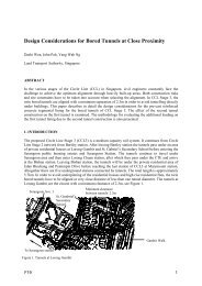
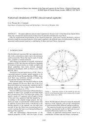
Figure 2.<br />
Tunnel alignments.<br />
Figure 3.<br />
Typical cross section and ground conditions.<br />
2 PROJECT DESCRIPTION<br />
The total length of the tunnel structure is 1398 m and<br />
comprises of a 241 m long Spine portal approach,<br />
969 m of reinforced concrete box section and 188 m<br />
of Crescent portal approach.<br />
The horizontal and vertical alignments were dictated<br />
by a maximum grade of 6% for a 60 kph design<br />
speed, in compliance with Dubai Municipality Geometric<br />
Design Manual for Dubai Roads (1999), and the<br />
need to ensure that the tunnel was sufficiently deep to<br />
maintain a 125 m wide arc-shaped navigation channel<br />
with a minimum draft of 10 m, above the 1.5 m thick<br />
layer of armour protection on the roof slab. The vertical<br />
alignment and the horizontal alignment, which is a<br />
reverse curve with a central straight section, are shown<br />
in Figure 2.<br />
Mean sea level is +1.0 mDMD (Dubai Municipality<br />
Datum, which is 0.09 m below Admiralty Chart<br />
Datum) with a tidal range of 1.2 m between MHHW<br />
and MLLW. The reclaimed islands are at +3 m and<br />
+4 mDMD at the Spine and Crescent, respectively.<br />
Seabed elevations before The Palm reclamation were<br />
in the range −11 m to −12 mDMD. Pre-construction<br />
surveys indicated that the minimum seabed elevation<br />
along the tunnel alignment and the cofferdam<br />
region was −15 m and −19 mDMD respectively, in<br />
areas where materials had been won for breakwater<br />
construction.<br />
A Design and Build contract was awarded to Taisei<br />
Corporation in 2004 for the construction of the<br />
vehicular tunnel.<br />
3 GEOLOGY AND GROUND CONDITIONS<br />
The local geology in the vicinity of the project site<br />
has been shaped by the current hot arid climate and<br />
by fluctuations in sea level and is described by <strong>Gahir</strong><br />
et al. (2006).<br />
Ground conditions were determined by sinking 13<br />
offshore boreholes to a depth of 30 m into the seabed<br />
and 3 boreholes up to 30 m depth on the onshore<br />
reclamation. The minimum elevation explored is<br />
−45 mDMD. The offshore boreholes were drilled<br />
along the alignment of the dykes and are offset up to<br />
230 m from the tunnel centre line. All boreholes were<br />
grouted after completion.<br />
The boreholes revealed that under a 12 m thick<br />
recent fill a 1 m to 2 m thick band of weak caprock<br />
is present which in turn is underlain by 2 m to 4 m<br />
thick layer of medium dense sand. The sand overlies<br />
an 18 m to 22 m thick sequence of very weak to weak<br />
interbedded calcarenite and sandstone. A conglomerate<br />
layer whose upper horizon is some −35 mDMD is<br />
present across the site (Figure 3). The UCS of rock<br />
encountered is in the range 1 to 3.5 MPa. In isolated<br />
boreholes a thin layer of soft silt was recorded<br />
1298