Geotechnical risk management for tunneling beneath open water
Geotechnical risk management for tunneling beneath open water
Geotechnical risk management for tunneling beneath open water

Create successful ePaper yourself
Turn your PDF publications into a flip-book with our unique Google optimized e-Paper software.
Underground Space – the 4 th Dimension of Metropolises – Barták, Hrdina, Romancov & Zlámal (eds)<br />
© 2007 Taylor & Francis Group, London, ISBN 978-0-415-40807-3<br />
<strong>Geotechnical</strong> <strong>risk</strong> <strong>management</strong> <strong>for</strong> <strong>tunneling</strong> <strong>beneath</strong> <strong>open</strong> <strong>water</strong><br />
D.P. Richards<br />
Parsons Brinckerhoff, Portland OR, USA.<br />
B. Nilsen<br />
Norwegian University of Science and Technology (NTNU), Trondheim, Norway<br />
ABSTRACT: Tunnel construction <strong>beneath</strong> <strong>open</strong> bodies of <strong>water</strong> presents certain types of <strong>risk</strong>s not encountered<br />
when <strong>tunneling</strong> <strong>beneath</strong> “dry land”. If major problems develop with tunnel equipment, ground control, or ground<br />
<strong>water</strong> control, construction personnel are exposed to <strong>risk</strong> of catastrophic flooding in the tunnel and recovery<br />
operations from the surface are generally not possible. Under these construction conditions, <strong>management</strong> of<br />
geotechnical <strong>risk</strong> during construction is of paramount importance. This paper addresses some of the more critical<br />
<strong>risk</strong>s that must be considered and evaluated <strong>for</strong> such tunnel construction, starting with the planning process,<br />
and continuing through design and construction. Due to the increased difficulty and expense of geotechnical site<br />
exploration under <strong>water</strong>, the extent of the site investigation is sometimes decreased rather than increased, increasing<br />
the geotechnical uncertainty, requiring more detailed planning of construction methods and sequences, and<br />
appropriate redundancies and contingencies. The paper discusses the investingation, planning and construction<br />
processes <strong>for</strong> both soft ground and hard rock tunnels, and both conventional and machine excavation.<br />
1 INTRODUCTION<br />
The planning, design and construction of underground<br />
facilities <strong>beneath</strong> <strong>open</strong> <strong>water</strong> is always a challenge. In<br />
contrast to on-shore tunnel operations, when ground<br />
and/or ground <strong>water</strong> control problems are encountered,<br />
the physical constraint of no access from above <strong>for</strong><br />
recovery operations when problems are encountered,<br />
introduces a higher degree of <strong>risk</strong> during construction,<br />
requiring an increase in the level of ef<strong>for</strong>t in the<br />
site investigation, design detailing and construction<br />
planning.<br />
2 GEOTECHNICAL RISKS<br />
<strong>Geotechnical</strong> <strong>risk</strong>s are always a challenge in any tunnel<br />
project, and must be accounted <strong>for</strong> to minimize <strong>risk</strong><br />
during construction, but <strong>for</strong> under <strong>water</strong> projects, the<br />
<strong>risk</strong>s are often higher due to site investigation limitations<br />
and restrictions in addressing ground and ground<br />
<strong>water</strong> control problems during construction. <strong>Geotechnical</strong><br />
<strong>risk</strong>s that must be identified and accounted <strong>for</strong><br />
in the investigation, design, and construction planning<br />
include:<br />
• General profiling of the bottom surface<br />
• Identification of low spots in the bottom profile<br />
• Depth and character of sediments<br />
1585<br />
• Variations in type and character of bedrock<br />
• Location and extent of geological weaknesses<br />
• Identification of rock structure patterns<br />
• Characterization of the in-situ permeability<br />
Potential <strong>risk</strong>s associated with construction of hard<br />
rock subsea tunnels may be illustrated by the following<br />
examples from Norwegian projects (Blindheim et.al.,<br />
2005):<br />
• The Bjorøy tunnel (1996), where a more than 10 m<br />
wide fault zone filled with clay, sand and coal fragments<br />
quite unexpectedly encountered. This was<br />
a zone of extremely high permeability and very<br />
poor stability, and a very time-consuming procedure<br />
involving stepwise grouting, drainage, spiling and<br />
shotcrete arches was necessary to tunnel through it.<br />
• The North Cape tunnel (1999), where flat lying, broken<br />
sedimentary rocks caused very poor stability,<br />
resulting in slow progress and requiring shotcrete<br />
and concrete lining at the face. The difficult conditions<br />
were not realized from the pre-investigations<br />
due to the relatively high seismic velocity of the flat<br />
lying layers (4,500–5,500 m/sec).<br />
• The Oslofjord tunnel (2000), where a deep cleft<br />
filled with Quaternary soil was encountered, necessitating<br />
ground freezing to tunnel through.A distinct<br />
weakness zone was detected prior to tunnelling.<br />
Despite very comprehensive pre-investigations
100<br />
200<br />
BH 4-1 BH 2 Tarva fault<br />
BH 3-1<br />
BH 3-2<br />
BH 5-1<br />
Hitra loose material<br />
Fröya<br />
0<br />
2.5<br />
1<br />
low seismic velocity zone<br />
weakness zone in tunnel<br />
core drill hole<br />
0 500 1000 1500 2000 3000 4000 5000<br />
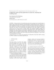
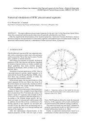
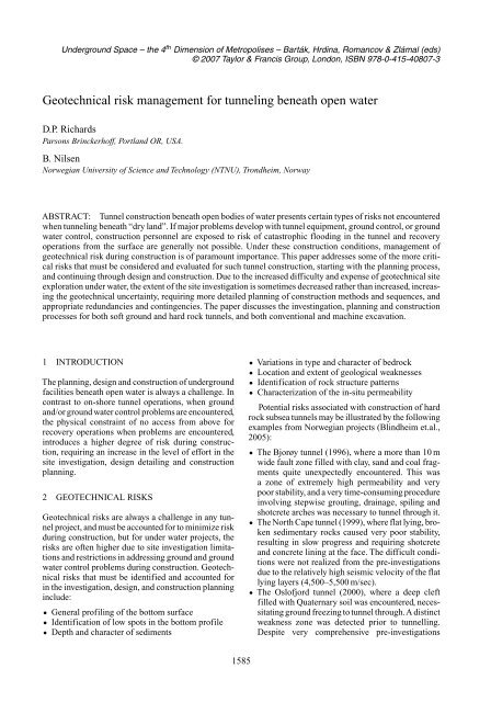
Figure 1. Longitudinal section illustrating low velocity/weakness zones in the Frøya tunnel (from Nilsen & Palmstrøm,<br />
2001).<br />
including traditional refraction seismics as well as<br />
directional core drilling and seismic tomography it<br />
was not found that the zone was eroded to a deep<br />
cleft.A by-pass tunnel was prepared to allow continued<br />
<strong>tunneling</strong> under the fjord. The soil filled section<br />
was frozen (at 120 m <strong>water</strong> pressure) and excavated<br />
through.<br />
• At one of the most recent Norwegian projects, the<br />
Frøya sub sea tunnel, a pattern of very distinct,<br />
regional faults was identified by pre-construction<br />
investigations. Some of these faults could be followed<br />
over a distance of more than 200 km.<br />
Challenging ground conditions were documented,<br />
including high permeability zones as well as weakness<br />
zones containing very loose, sandy material<br />
and extremely active swelling clay. The locations of<br />
the main weakness zones are shown in Figure 1.<br />
In the planning of the Frøya tunnel, great benefit<br />
was gained from the previous construction of<br />
the nearby Hitra tunnel, where the major fault in<br />
the fjord was found to consist mainly of a mixture<br />
of heavily crushed rock and clay minerals (including<br />
swelling clay). The <strong>water</strong> seepage through the<br />
zone was minimal, and a combination of short blast<br />
rounds, spiling, steel fiber rein<strong>for</strong>ced shotcrete,<br />
straps and conventional rock bolts, was used <strong>for</strong><br />
getting through it.<br />
The <strong>risk</strong>s noted above <strong>for</strong> conventionally excavated<br />
drill and blast tunnels are similar <strong>for</strong> hard rock TBM<br />
tunnels, but they are sometimes more difficult to cope<br />
with using a TBM, due to limited access to the face <strong>for</strong><br />
grouting or other ground improvement procedures, as<br />
well as problems in getting around aTBM if it becomes<br />
stuck. Aside from ground <strong>water</strong> inflows being a potential<br />
<strong>risk</strong>, other geological <strong>risk</strong>s such as unanticipated<br />
faults or intrusions, either associated with an increase<br />
in fracture frequency, increases (or decreases) in rock<br />
strength, and increased abrasion also become more<br />
significant <strong>for</strong> a TBM excavation.<br />
Significant <strong>risk</strong>s <strong>for</strong> soft ground tunnels are mostly<br />
related to pressurized face TBM driven tunnels, since<br />
compressed air as a ground and/or ground <strong>water</strong> control<br />
technology is being replaced by improvements<br />
in soft ground TBM technology. Considering this<br />
1586<br />
though, there are still significant <strong>risk</strong>s, mainly related<br />
to the presence of unanticipated ground conditions<br />
such as higher permeability, higher/lower cohesion,<br />
presence of boulders, buried obstruction, abandoned<br />
exploratory boreholes, extremely weak (or strong)<br />
materials, increased abrasiveness etc.<br />
3 SITE INVESTIGATION AND PLANNING<br />
3.1 General<br />
A comprehensive site investigation is critical to the<br />
successful planning and execution of a tunnel <strong>beneath</strong><br />
<strong>open</strong> <strong>water</strong>. Due to the additional expense and technical<br />
difficulties involved in off-shore drilling, vertical<br />
borings penetrating to tunnel level are often limited,<br />
and are often supplemented by directional drilling<br />
<strong>beneath</strong> the <strong>water</strong>, and by the use of marine geophysics.<br />
Geophysical techniques often considered <strong>for</strong><br />
such off-shore investigations include:<br />
• Hydrographic surveys: River, lake, or ocean floor<br />
bathymetric mapping<br />
• Multibeam sonar: Multichannel hydrographic surveying<br />
that records a wide swath of data<br />
• Sub-bottom sonar profiling: Detection of layering<br />
<strong>beneath</strong> the floors of rivers, lakes, or oceans<br />
• Marine Seismic Reflection: Multichannel profiling<br />
of sediment and rock layering <strong>beneath</strong> the floors of<br />
rivers, lakes, or oceans<br />
• Marine Seismic Refraction: For mapping of thickness<br />
and character of sediments, rock mass characterization<br />
and faults/weakness zones based on<br />
seismic velocity (see also Figure 1)<br />
• Seismic tomography: Investigation of rock mass<br />
character between drill holes or between drill hole<br />
and sea floor<br />
• Marine Magnetometry: For mapping of rock type<br />
boundaries and weathering<br />
• Electrical Imaging: Two-dimensional (crosssectional)<br />
imaging of sub-bottom electrical properties<br />
to detect and delineate sand, clay or gravel<br />
lenses, bedrock fractures – sensitive to <strong>water</strong><br />
salinity.
Figure 2. Conventional and directional core drilling at critical part of the Oslofjord tunnel (after Palmstrøm et.al., 2003).<br />
In addition, conventional site investigation requirements<br />
are applicable, including sampling <strong>for</strong><br />
determination of strength, weathering, mineralogy,<br />
de<strong>for</strong>mation characteristics, porosity, abrasion potential,<br />
as required to make decisions with respect to<br />
applicable construction methods. For hard rock this<br />
would be a decision between tunnel boring machine<br />
and conventional excavation by drill and blast techniques.<br />
For soft ground, this would be a decision<br />
between types of pressurized closed face tunnel boring<br />
machines – slurry shield or EPB technology.<br />
3.2 Norwegian hard rock practice<br />
As a supplement to normal geological surveys, seismic<br />
investigations are crucial in the first stages. Acoustic<br />
profiling is first carried out <strong>for</strong> a large area to determine<br />
the most suitable corridor. Extensive refraction<br />
seismics is then carried out to select the best alignment<br />
and to provide in<strong>for</strong>mation about soil deposits above<br />
the bedrock and about weakness (low velocity) zones<br />
in the bedrock. If possible, directional core drilling as<br />
illustrated in Figure 2 is used from shore to the critical<br />
deepest points of the alignment, which typically also<br />
could be the location of major fault zones. Core drilling<br />
from drilling ships has been applied in a few cases in<br />
Norway, when other drilling has not been feasible.<br />
The costs <strong>for</strong> the site investigations <strong>for</strong> Norwegian<br />
sub sea tunnels typically amount to 3–7% of<br />
the construction costs. The established practice of site<br />
investigations has proven to be reliable, but exceptions<br />
have occurred as noted above.<br />
Optimizing the minimum rock cover is crucial<br />
<strong>for</strong> safety as well as economy. Increased rock cover<br />
makes the tunnel unnecessarily long, representing<br />
extra construction costs and increased operating and<br />
traffic costs over the project’s lifetime. Too little rock<br />
cover may cause severe stability problems, unacceptable<br />
work safety, heavy <strong>water</strong> ingress, and need <strong>for</strong><br />
excessive grouting and high pumping costs.<br />
A minimum rock cover of 50 m is basically required.<br />
A rock cover of less than 50 m can be accepted when<br />
1587<br />
detailed site investigations have demonstrated fair rock<br />
mass conditions (taking into account the typical occurrence<br />
of fault zones at the deepest point). This is left<br />
<strong>open</strong> to interpretation and rock cover less than 20 m<br />
has been used, but is then typically restricted to shallow<br />
<strong>water</strong>s and <strong>for</strong> good rock conditions.<br />
3.3 Hard rock TBM tunnels<br />
Investigation requirements <strong>for</strong> TBM tunnels in hard<br />
rock are similar to those <strong>for</strong> conventional excavation,<br />
since the <strong>risk</strong>s are similar. However, as noted above,<br />
ground and/or ground <strong>water</strong> control problems are often<br />
more difficult to cope with <strong>for</strong> aTBM excavation, often<br />
making the understanding and reliability of geological<br />
conditions a bit more critical.<br />
3.4 Soft ground tunnels<br />
Soft ground tunnels passing <strong>beneath</strong> <strong>open</strong> <strong>water</strong> are<br />
usually relatively shallow. For example, transportation<br />
tunnels passing <strong>beneath</strong> rivers or shallow bays or channels<br />
usually have the depth restricted by the gradient<br />
of the approaches to the tunnel.<br />
While site investigation practices <strong>for</strong> such soft<br />
ground tunnels are very similar to those identified<br />
above <strong>for</strong> hard rock tunnels, they must also include<br />
adequate material property characterization to allow<br />
in<strong>for</strong>med decisions to be made with respect to soft<br />
ground TBM technology. The usual material property<br />
tests contributing to the ability to make these<br />
decisions include density, permeability, gradation, and<br />
plasticity.<br />
For these applications, conventional sampling by<br />
both Standard Penetration Testing (SPT), and recovery<br />
of “undisturbed” samples are both commonly used, in<br />
addition to CPT (Cone PenetrationTest). For such shallow<br />
soft ground applications in historic urban areas,<br />
it is often required to identify buried obstructions<br />
such as sunken ships and abandoned foundation piles,<br />
both of which can often be detected by geophysical<br />
techniques.
4 CONSTRUCTIONAL ASPECTS<br />
4.1 General<br />
It is during the construction planning phase, that final<br />
decisions must be made <strong>for</strong> the appropriate selection<br />
of means and methods of construction best suited to<br />
the subsurface geological conditions identified during<br />
the site investigation phase. These selected means<br />
and methods of construction must be an integral component<br />
of the <strong>risk</strong> <strong>management</strong> process, and must<br />
be chosen to best satisfy the intent of the mitigation<br />
measures <strong>for</strong> reducing <strong>risk</strong> exposure.<br />
Key considerations in selecting construction means<br />
and methods <strong>for</strong> hard rock tunnels include:<br />
• Rock types, distribution, and conditions<br />
• Rock properties; strength, hardness, abrasiveness<br />
• Discontinuity characteristics; frequency, orientations,<br />
continuity, roughness<br />
• Major structural features; fault number, orientation,<br />
thickness, character<br />
Key considerations in selection of construction<br />
means and methods <strong>for</strong> soft ground tunnels include:<br />
• Thickness of overburden cover<br />
• Soil type, layering, stiffness/relative density<br />
• Soil properties; plasticity, gradation, permeability<br />
• Hard inclusions; boulders, cemented zones<br />
• Hydrostatic <strong>water</strong> pressure<br />
• Ground <strong>water</strong> chemistry<br />
4.2 Hard rock conventional excavation tunnels<br />
The Norwegian hard rock sub sea tunnels have all been<br />
excavated by drilling and blasting. This method provides<br />
great flexibility and adaptability to varying rock<br />
mass conditions and is cost effective.<br />
Systematic percussive probe drilling with the<br />
drilling jumbo is most critical <strong>for</strong> safety. By applying<br />
criteria related to inflow per probe hole on when<br />
to pre-grout, the remaining inflow can be controlled<br />
and adapted to preset quantities <strong>for</strong> economical pumping,<br />
which is normally 300 liters/min per km. Grouting<br />
against <strong>water</strong> pressures of 2∼3 MPa can be efficiently<br />
achieved with modern packers, pumps and grouting<br />
materials. Grouting pressures up to 10MPa are today<br />
quite common. Follow-up at the tunnel face by well<br />
qualified engineering geologists (and rock engineers)<br />
is of great importance.<br />
In the Norwegian projects, all rock support structures<br />
are drained, whether they are made of castin-place<br />
concrete (mostly horseshoe) lining, sprayed<br />
concrete ribs or sprayed concrete. Sprayed concrete<br />
is dominantly applied as wet mix steel fiber rein<strong>for</strong>ced.<br />
Extensive testing demonstrates that, if the<br />
thickness of the sprayed concrete is above a minimum<br />
of 60–70 mm, and the concrete quality is good (C45),<br />
1588<br />
corrosion of steel fibers is not a problem. Rock bolts<br />
have extensive corrosion protection. Rock support is<br />
always adjusted to the actual rock mass conditions,<br />
with heavy support applied only in very poor stability<br />
conditions. The use of spiling and shotcrete ribs has<br />
mostly replaced a concrete lining.<br />
4.3 Hard rock TBM tunnels<br />
Although numerous rock TBMs are operating around<br />
the world, many below the static ground <strong>water</strong> table,<br />
not all of these pass <strong>beneath</strong> <strong>open</strong> <strong>water</strong>. As with any<br />
rockTBM, good ground conditions usually allow good<br />
TBM excavation rates. However, as noted by McLearie<br />
et.al. (2001) <strong>for</strong> bored rock tunnels recently completed<br />
in Hong Kong, tunnel excavation success was largely<br />
dependent upon ground and ground <strong>water</strong> conditions,<br />
with intensely fractured zones (faults and dikes) often<br />
introducing large amounts of ground <strong>water</strong> infiltration,<br />
requiring extensive cut-off grouting be<strong>for</strong>e the TBM<br />
could progress, delaying the schedule and increasing<br />
the costs.<br />
At the opposite end of the spectrum, was the Channel<br />
Tunnel, where ground conditions were ideal <strong>for</strong><br />
TBM excavation in the relatively consistent chalks<br />
and chalk marls (Varley et.al., 1992 and Barthes et.al.,<br />
1994a). As noted by Barthes et.al., (1994b), although<br />
the chalks were relatively consistent on both sides of<br />
the channel, the French side was more faulted, with<br />
higher in-situ permeabilities, and these factors influenced<br />
the selection of TBMs as well as other means<br />
and methods of construction.<br />
4.4 Soft ground tunnels<br />
A fairly recent example of a large diameter soft ground<br />
tunnel excavated by a pressurized face TBM <strong>beneath</strong><br />
<strong>open</strong> <strong>water</strong>, was the crossing <strong>beneath</strong> the Nile River<br />
by the Cairo Metro Line 2 bored tunnels in Egypt<br />
(Richards et.al., 1998). This was excavated by a 9.43<br />
meter diameter slurry shield TBM in dense saturated<br />
sands and crossed two separate branches of the river.<br />
A subsurface profile is shown in Figure 3.<br />
Prior to starting the tunnel bore <strong>beneath</strong> the river,<br />
a <strong>risk</strong> assessment was per<strong>for</strong>med, addressing both<br />
design, construction, and long term per<strong>for</strong>mance<br />
issues. Based upon this <strong>risk</strong> assessment, a number<br />
of design issues were double checked to ensure<br />
adequate construction term and long term per<strong>for</strong>mance<br />
of the tunnel. This <strong>risk</strong> assessment was also<br />
used <strong>for</strong> construction planning, in which emergency<br />
response plans, contingency plans and appropriate<br />
redundant construction systems were identified and<br />
implemented.<br />
Key issues identified to minimize <strong>risk</strong> while <strong>tunneling</strong><br />
<strong>beneath</strong> the river included: maintenance of<br />
face stability, lining ring shape, ring position, reduce<br />
blowout <strong>risk</strong>, avoid bridge foundation, avoid TBM
Figure 3. Nile crossing subsurface profile (Richards et.al., 1998).<br />
break downs. Construction related contingency measures<br />
put into place to achieve these goals included:<br />
back-up electrical power, back-up compressed air supply,<br />
back-up locomotives, redundant slurry pumping<br />
equipment, extra reserve supply of bentonite, TBM<br />
improvement and/or modifications be<strong>for</strong>e passing<br />
<strong>beneath</strong> the river channel, and redundant communications<br />
between underground and topside personnel.<br />
The tunnel <strong>beneath</strong> the river was completed in<br />
two separate tunnel drives, with continuous operation<br />
until the TBM had safely passed <strong>beneath</strong> the <strong>open</strong><br />
<strong>water</strong> portion of the alignment. Both were completed<br />
without mishap, with no problems encountered which<br />
could not be handled by the contingency measures<br />
put into place prior to starting the excavation <strong>beneath</strong><br />
the river.<br />
5 RISK EVALUATION AND MANAGEMENT<br />
To better control the complexity of underground<br />
projects, new codes and guidelines <strong>for</strong> design, modern<br />
quality systems and special methodologies <strong>for</strong> <strong>risk</strong><br />
analyses have been introduced. Such tools provide a<br />
better basis <strong>for</strong> planning of investigation as well as<br />
construction and time/cost estimation.<br />
The basic principle <strong>for</strong> determining the extent of<br />
investigation should always be related to the type<br />
and complexity of the project, and to the prevailing<br />
geological conditions.<br />
A <strong>risk</strong> analysis may be divided into the following<br />
steps (Nilsen et.al., 1999; Pennington, et.al., 2006):<br />
1. Identification of hazards and damage events<br />
2. Assessment of probabilities <strong>for</strong> hazards and damage<br />
events identified<br />
3. Description and valuation of consequences including<br />
analysis of initiating events<br />
4. Calculation of pre-mitigation <strong>risk</strong> rating<br />
5. Identification of appropriate mitigation measures<br />
<strong>for</strong> each <strong>risk</strong><br />
6. Calculation of post-mitigation <strong>risk</strong> rating<br />
1589<br />
Within a project, <strong>risk</strong> analysis and quality control/assurance<br />
should be focused upon:<br />
• Identifying and elimination or reducing hazards<br />
• Reducing the probability of initiating events<br />
• Finding barriers to stop damage events<br />
• Reducing the consequence of possible damage<br />
• Implementation of mitigation measures<br />
The types of geotechnical <strong>risk</strong>s to be considered<br />
include:<br />
• Hard rock tunnels<br />
– Geology more complicated than anticipated<br />
– Weathering deeper than anticipated<br />
– Rock stronger or weaker than anticipated<br />
– More/wider fault zones than anticipated<br />
– Rock more fractured than anticipated<br />
– Rock more abrasive than anticipated<br />
– Rock mass (including fractured/faulted zones)<br />
permeability higher than anticipated<br />
– More voids (e.g. karst) than anticipated<br />
• Soft ground tunnels<br />
– Bottom profile more irregular than anticipated<br />
– Sediments softer/harder or stiffer/denser than<br />
anticipated<br />
– Soils more granular /cohesive than anticipated<br />
– In-situ permeability greater than anticipated<br />
– Soil profile more irregular than anticipated<br />
– More boulders or inclusions than anticipated<br />
Hazards and uncertainties are not only related to<br />
the soil or rock, but also with people involved in a<br />
project. A major task within <strong>risk</strong> analysis is to understand,<br />
describe and handle uncertainties. The Frøya<br />
sub sea tunnel case may be used to illustrate this. Here,<br />
the refraction seismic measurements showed more low<br />
velocity (weakness) zones than <strong>for</strong> any of the subsea<br />
tunnel previously constructed in Norway. In addition,<br />
the core drillings penetrated long sections of rocks with<br />
weakness zones having a higher degree of alteration<br />
than is normal in Norwegian hard rocks. The results
of the investigations indicated that the Frøya tunnel<br />
required thorough evaluations to assess its feasibility,<br />
and that special routines be implemented during<br />
planning and construction.<br />
As a part of this, two groups were established to<br />
evaluate the feasibility of the tunnel. In their two<br />
independent reports excavation methods and rock support<br />
were analyzed, supported by a cost estimate and<br />
<strong>risk</strong> assessment. Construction time and cost estimates<br />
were based on a detailed prognosis of the expected<br />
ground conditions, and the estimate proved to correspond<br />
quite well with reality (Palmstrøm et.al, 2000).<br />
6 DISCUSSION AND CONCLUSIONS<br />
Tunneling <strong>beneath</strong> <strong>open</strong> <strong>water</strong> is usually more challenging<br />
them landside operation, often with a higher<br />
degree of uncertainty and <strong>risk</strong>. The following lessons<br />
of general relevancy <strong>for</strong> the planning of future projects<br />
are applicable.<br />
• The extent of ground investigation and planning<br />
should always reflect the complexity of the geology,<br />
the type of project, and the degree of <strong>risk</strong>.<br />
• Risk assessment should start in the planning phase<br />
and carry on in design and construction.<br />
• The results from the investigations should be properly<br />
documented and their use in calculations and<br />
assessments shown.<br />
• The geological setting and understanding of the<br />
tectonic are vital <strong>for</strong> all large tunnel projects.<br />
• Ground investigations where the extent is based on<br />
bidding, may cause vital in<strong>for</strong>mation to be lost, and<br />
should never be accepted.<br />
• Sufficient time must be allocated <strong>for</strong> necessary<br />
investigations and testing.<br />
• The ground investigations should continue through<br />
the entire construction period. Tunnel mapping and<br />
following up should be done by experienced engineering<br />
geologists representing owner as well as<br />
contractor.<br />
• Risk analysis, assessment of uncertainties and<br />
development of mitigation measures are critical.<br />
• The tender documents, including geological/<br />
hydrological/hydrographic reports, should be thoroughly<br />
prepared, with full quality control.<br />
• An independent reference committee should be<br />
established. For the construction period, strict<br />
requirements should be put on the engineer’s and<br />
contractor’s competency and qualifications.<br />
• Planning and investigation should always carry <strong>risk</strong><br />
assessment <strong>for</strong>ward to the detailed design and construction<br />
phases, since residual <strong>risk</strong> remains, even<br />
after significant and relevant site investigations.<br />
1590<br />
REFERENCES<br />
Barthes, H., A. Bordas, D. Bouillot, M. Buzon, Ph. Dumont,<br />
J. Fermin, J.-C. Landry, J.-P. Larive, J.-J. Morlot, L.<br />
Szypura, Ph. Vandebrouck and B. Vielliard. 1994a. “Tunnels<br />
– Geology”, Paper # 10486, Proceedings Institution<br />
of Civil Engineers, Supplement to Civil Engineering, Vol.<br />
102, Special Issue No. 1 – The Channel Tunnel, Part 3:<br />
French Section, ICE, London.<br />
Barthes, H., A. Bordas, D. Bouillot, M. Buzon, Ph. Dumont,<br />
J. Fermin, J.-C. Landry, J.-P. Larive, J.-J. Morlot, L.<br />
Szypura, Ph. Vandebrouck and B. Vielliard. 1994b. “Tunnels<br />
– Tunnel Boring Machines”, Paper # 10489, Proceedings<br />
Institution of Civil Engineers, Supplement to Civil<br />
Engineering, Vol. 102, Special Issue No. 1 – The Channel<br />
Tunnel, Part 3: French Section, ICE, London.<br />
Blindheim O.T., Grøv E. & Nilsen B. 2005. Nordic sub<br />
sea tunnel projects. Tunnelling and Underground Space<br />
Technology, 20:570–580.<br />
CEN 1997. <strong>Geotechnical</strong> design – Part 1: General rules.<br />
European Pre-standard ENV 1997–1, Comite Europeen<br />
de Normalisation, 123 p.<br />
McLeary, D.D.,W. Foreman,W.H. Hansmire and E.K.H.Tong.<br />
2001. “Hong Kong Strategic Sewage Disposal Scheme<br />
Stage I DeepTunnels”, Proceedings Rapid Excavation and<br />
Tunneling Conference, Society of Mining Engineerrs, pp.<br />
487–408, Littleton, CO, USA.<br />
Nilsen B. & Palmstrøm A. 2001. Stability and <strong>water</strong> leakage<br />
of hard rock subsea tunnels. Proc. Int. Symp. IS-Kyoto,<br />
2001, Balkema, pp. 497–502.<br />
Nilsen B., Palmstrøm A. & Stille H. 1999. Quality control<br />
of sub-sea tunnel project in complex ground conditions.<br />
Proc. ITA World Tunnel Congress Oslo, June 199.<br />
Balkema, pp. 137–145.<br />
Palmstrøm A., Stille H. & Nilsen B. 2000. The Frøya tunnel<br />
– a sub sea tunnel in complex ground conditions. Proc.<br />
Swedish Rock Mechanics Meeting, Stockholm March<br />
2000, BeFo, pp. 19–30.<br />
Palmstrøm,A., Nilsen, B., Pedersen, K.B. & Grundt, L. 2003.<br />
Optimum extent of site investigations <strong>for</strong> underground<br />
facilities. Publ. No. 101, Directorate of Public Roads,<br />
116 p. (in Norwegian).<br />
Pennington, T.W., R.F. Cook, D.P. Richards, J. O’Carroll,<br />
and T. Cleys. 2006. “A tunnel case study in <strong>risk</strong> <strong>management</strong>”,<br />
Proceedings, NorthAmericanTunneling, Chicago,<br />
Illinois, Taylor & Francis, London.<br />
Richards, D.P, P. Ramond, and O. Ezzeldine. 1998. “Design<br />
and construction of the first bored tunnel across<br />
the Nile River”, Proceedings, ITA Congress, Tunnels<br />
and Metropolises, Sao Paulo, Brazil, A.A. Balkema,<br />
Rotterdam.<br />
Varley, P., A. Darby and E. Radcliff. 1992. “Geology,<br />
Alignment and Survey”, Paper # 9932, Proceedings Institution<br />
of Civil Engineers, Supplement to Civil Engineering,<br />
The Channel Tunnel, Part 1: Tunnels, ICE, London.