LMS-525C DF & LMS-520C Manual - Lowrance
LMS-525C DF & LMS-520C Manual - Lowrance
LMS-525C DF & LMS-520C Manual - Lowrance

Create successful ePaper yourself
Turn your PDF publications into a flip-book with our unique Google optimized e-Paper software.
www.lowrance.com<br />
Pub. 988-0151-461<br />
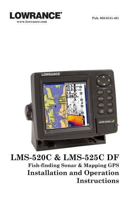
<strong>LMS</strong>-<strong>520C</strong> & <strong>LMS</strong>-<strong>525C</strong> <strong>DF</strong><br />
Fish-finding Sonar & Mapping GPS<br />
Installation and Operation<br />
Instructions
Copyright © 2006 <strong>Lowrance</strong> Electronics, Inc.<br />
All rights reserved.<br />
No part of this manual may be copied, reproduced, republished, transmitted<br />
or distributed for any purpose, without prior written consent of<br />
<strong>Lowrance</strong>. Any unauthorized commercial distribution of this<br />
manual is strictly prohibited.<br />
<strong>Lowrance</strong> ® is a registered trademark of <strong>Lowrance</strong> Electronics, Inc.<br />
MapCreate, FreedomMaps and NauticPath are trademarks of<br />
LEI. Fishing Hot Spots ® is a registered trademark of Fishing Hot Spots<br />
Inc. LakeMaster ® and Pro Maps are trademarks or registered trademarks<br />
of WayPoint Technologies, Inc. Navionics ® is a registered<br />
trademark of Navionics, Inc. DURACELL ® is a registered trademark of<br />
Duracell, Inc. RAYOVAC ® is a registered trademark of Rayovac Corporation.<br />
Energizer ® and e 2® are registered trademarks of Energizer Holdings,<br />
Inc.<br />
Points of Interest Data in this unit are by infoUSA,<br />
copyright © 2001-2006, All Rights Reserved. infoUSA is a<br />
trademark of infoUSA, Inc.<br />
<strong>Lowrance</strong> Electronics may find it necessary to change or end our policies,<br />
regulations and special offers at any time. We reserve the right to<br />
do so without notice. All features and specifications subject to change<br />
without notice. All screens in this manual are simulated. On the cover:<br />
<strong>LMS</strong>-<strong>525C</strong><strong>DF</strong>.<br />
For free owner's manuals and the most current information on<br />
this product, its operation and accessories,<br />
visit our web site:<br />
www.lowrance.com<br />
<strong>Lowrance</strong> Electronics Inc.<br />
12000 E. Skelly Dr.<br />
Tulsa, OK USA 74128-2486<br />
Printed in USA.
Table of Contents<br />
Section 1: Read Me First! ......................................................... 1<br />
Specifications: <strong>LMS</strong>-520c and <strong>LMS</strong>-525c<strong>DF</strong>.......................... 3<br />
How to use this manual: typographical conventions ................ 10<br />
Section 2: Installation............................................................. 13<br />
Preparations ................................................................................ 13<br />
Transducer Installation .............................................................. 13<br />
Single-frequency transom installations............................. 14<br />
Dual-frequency transom installations ............................... 14<br />
Single-frequency trolling motor installations ................... 14<br />
Shoot-through hull installations ........................................ 14<br />
Selecting a Transducer Location............................................ 14<br />
How low should you go? .......................................................... 16<br />
Shoot-thru-hull vs. Transom Mounting................................. 16<br />
Transom Transducer Assembly And Mounting .................... 17<br />
Trolling Motor Bracket Installation (single-frequency only) 23<br />
Transducer Orientation and Fish Arches.............................. 23<br />
Shoot-Thru-Hull Preparation ................................................. 24<br />
Hulls with Flotation Materials........................................... 24<br />
Testing Determines Best Location......................................... 25<br />
Shoot-thru-hull Installation ................................................... 27<br />
Speed/Temperature Sensors ................................................. 28<br />
Optional Speed Sensor Installation ....................................... 28<br />
Power Connections...................................................................... 30<br />
Powering Your Display Unit ...................................................... 31<br />
Power Diagram A ........................................................................ 32<br />
Power Diagram B ........................................................................ 33<br />
Powering a NMEA 2000 Network Bus ...................................... 33<br />
GPS Antenna/Receiver Module .................................................. 34<br />
Connecting to a NMEA 2000 Network ...................................... 35<br />
NMEA 0183 Wiring (Data cable) ........................................... 36<br />
Mounting the Unit: Bracket, In-Dash or Portable.................... 39<br />
MMC or SD Card Memory Card Installation............................ 42<br />
Other Accessories ........................................................................ 44<br />
Cleaning Towel........................................................................ 44<br />
Face Cover ................................................................................... 45<br />
Section 3: Basic Sonar Operation ........................................ 47<br />
Keyboard...................................................................................... 47<br />
Power/lights on and off ............................................................... 48<br />
Main Menu................................................................................... 48<br />
Pages ............................................................................................ 50<br />
Satellite Status Page............................................................... 50<br />
Navigation Page ...................................................................... 51<br />
i
Map Page ................................................................................. 51<br />
Sonar Page ............................................................................... 52<br />
Basic Sonar Quick Reference ............................................... 55<br />
Sonar Operations ........................................................................ 56<br />
Fish Symbols vs. Full Sonar Chart ........................................ 58<br />
Section 4: Sonar Options........................................................ 61<br />
ASP (Advanced Signal Processing)......................................... 61<br />
Alarms.......................................................................................... 62<br />
Depth Alarms .......................................................................... 62<br />
Zone Alarm .............................................................................. 63<br />
Fish Alarm ............................................................................... 64<br />
GPS Alarms ............................................................................. 65<br />
NMEA 2000 Alarms .................................................................... 66<br />
Calibrate Speed ........................................................................... 67<br />
Chart Speed ................................................................................. 68<br />
Colorline ................................................................................... 69<br />
Depth Cursor ............................................................................... 70<br />
Depth Range - Automatic ........................................................... 71<br />
Depth Range - <strong>Manual</strong>................................................................ 71<br />
Depth Range - Upper and Lower Limits ................................... 72<br />
FasTrack................................................................................... 73<br />
Fish I.D. (Fish Symbols & Depths) ......................................... 74<br />
FishTrack.................................................................................. 76<br />
Frequency (Change Transducer Frequency) ............................. 76<br />
HyperScroll............................................................................... 77<br />
Log Sonar Chart Data................................................................. 78<br />
Noise Rejection ............................................................................ 79<br />
Overlay Data ............................................................................... 79<br />
Ping Speed & HyperScroll....................................................... 82<br />
Reset Options............................................................................... 83<br />
Reset Water Distance.................................................................. 84<br />
Set Keel Offset............................................................................. 84<br />
Sensitivity & Auto Sensitivity.................................................... 85<br />
Automatic Sensitivity ............................................................. 86<br />
Sonar Chart Mode ....................................................................... 87<br />
Sonar Page & Sonar Chart Display Options ............................. 88<br />
Full Sonar Chart ..................................................................... 88<br />
Split Zoom Sonar Chart .......................................................... 89<br />
Split Frequency Sonar Chart (<strong>LMS</strong>-525c<strong>DF</strong> only)................ 89<br />
Digital Data/Chart .................................................................. 90<br />
Customize Page Displays........................................................ 90<br />
Flasher ..................................................................................... 92<br />
Sonar with Custom Gauges ........................................................ 92<br />
ii
Map with Sonar Split Screen.................................................. 94<br />
Sonar Simulator .......................................................................... 95<br />
Stop Chart.................................................................................... 97<br />
Surface Clarity ............................................................................ 98<br />
Transparency............................................................................... 99<br />
Upper and Lower Limits........................................................... 100<br />
Zoom & Zoom Bar...................................................................... 100<br />
Zoom Pan ................................................................................... 100<br />
Section 5: Sonar Troubleshooting ..................................... 101<br />
Section 6: Basic GPS Operations ....................................... 105<br />
Keyboard.................................................................................... 105<br />
Power/lights on and off ............................................................. 106<br />
Main Menu................................................................................. 106<br />
Pages .......................................................................................... 108<br />
Sonar Page ............................................................................. 108<br />
Satellite Status Page............................................................. 108<br />
Navigation Page .................................................................... 110<br />
Map Page ............................................................................... 113<br />
Map with Sonar ..................................................................... 117<br />
Map with Custom Gauges..................................................... 118<br />
Radar.......................................................................................... 119<br />
Basic GPS Quick Reference ................................................ 121<br />
Find Your Current Position...................................................... 122<br />
Moving Around the Map: Zoom & Cursor Arrow Keys........... 122<br />
Selecting Any Map Item with the Cursor................................ 123<br />
Searching ................................................................................... 123<br />
Set a Waypoint .......................................................................... 125<br />
Navigate To a Waypoint ........................................................... 127<br />
Set Man Overboard (MOB) Waypoint...................................... 127<br />
Navigate Back to MOB Waypoint ............................................ 128<br />
Navigate to Cursor Position on Map........................................ 128<br />
Navigate to a Point of Interest ................................................. 130<br />
Creating and Saving a Trail ..................................................... 130<br />
Displaying a Saved Trail .......................................................... 132<br />
Navigating Trails ...................................................................... 133<br />
Visual Trailing....................................................................... 133<br />
Navigate a Trail .................................................................... 133<br />
Navigate a Back Trail (backtrack) ....................................... 135<br />
Transfer Custom Maps and GPS Data Files........................... 136<br />
Cancel Navigation..................................................................... 138<br />
Section 7: Advanced GPS Operations.............................. 139<br />
Find Distance from different Locations................................... 139<br />
Find Distance from Point to Point ........................................... 139<br />
iii
Icons ........................................................................................... 140<br />
Create Icon on Map ............................................................... 140<br />
Create Icon at Current Position ........................................... 140<br />
Delete an Icon........................................................................ 140<br />
Navigate to an Icon ............................................................... 141<br />
Routes ........................................................................................ 141<br />
Create and Save a Route ...................................................... 142<br />
Delete a Route ....................................................................... 144<br />
Edit a Route Name................................................................ 145<br />
Edit Route Waypoints ........................................................... 145<br />
Navigate a Route................................................................... 146<br />
Navigate a Route in Reverse ................................................ 146<br />
Trails .......................................................................................... 147<br />
Delete a Trail......................................................................... 147<br />
Edit a Trail Name ................................................................. 148<br />
Edit a Trail Color .................................................................. 148<br />
Edit a Trail Pattern............................................................... 148<br />
Utilities ...................................................................................... 149<br />
Alarm Clock ........................................................................... 149<br />
Sun/Moon Rise & Set Calculator.......................................... 149<br />
Trip Calculator ...................................................................... 149<br />
Trip Down Timer ................................................................... 149<br />
Trip Up Timer........................................................................ 149<br />
Waypoints .................................................................................. 149<br />
Edit a Waypoint..................................................................... 150<br />
Selecting a Waypoint ............................................................ 150<br />
Create Waypoint by Entering a Position ......................... 151<br />
Set a Waypoint by Average Position.................................... 152<br />
Set a Waypoint by Projecting a Position.............................. 152<br />
Section 8: System & GPS Setup Options .......................... 153<br />
Alarms........................................................................................ 153<br />
Auto Satellite Search ................................................................ 154<br />
Check MMC Files and Storage Space...................................... 155<br />
Communications Port Configuration ....................................... 155<br />
Configure NMEA....................................................................... 156<br />
Coordinate System Selection.................................................... 156<br />
Map Fix ...................................................................................... 158<br />
Customize Page Displays.......................................................... 159<br />
GPS Simulator........................................................................... 160<br />
Hide GPS Feature ..................................................................... 162<br />
Initialize GPS ............................................................................ 162<br />
Map Auto Zoom ......................................................................... 163<br />
Map Data ................................................................................... 163<br />
iv
Map Datum Selection................................................................ 165<br />
Map Detail Category Selection................................................. 166<br />
Map Orientation........................................................................ 166<br />
NauticPath USA Marine Charts........................................... 168<br />
Nautical Chart Notes ............................................................ 168<br />
Port Information.................................................................... 169<br />
Tidal Current Information.................................................... 170<br />
Tide Information ................................................................... 172<br />
Navionics ® Charts ..................................................................... 173<br />
Overlay Data ............................................................................. 174<br />
Pop-up Help ............................................................................... 178<br />
Reset Options............................................................................. 179<br />
Screen Contrast and Brightness .............................................. 180<br />
Set Language............................................................................. 181<br />
Set Local Time........................................................................... 181<br />
Show WAAS Alarm ................................................................... 182<br />
Software Version Information.................................................. 183<br />
Sounds and Alarm Sound Styles.............................................. 184<br />
Track Smoothing ....................................................................... 185<br />
Trail Options.............................................................................. 185<br />
Update Trail Option.............................................................. 186<br />
Trail Visible/Invisible and Other Trail Options.................. 188<br />
Transparency............................................................................. 188<br />
Units of Measure ....................................................................... 189<br />
Section 9: Searching.............................................................. 193<br />
Find Streets ............................................................................... 194<br />
Find Any Item Selected by Map Cursor .................................. 195<br />
Find Interstate Highway Exits ................................................ 195<br />
Find Map Places or Points of Interest (POI) ........................... 198<br />
Find Streets or Intersections.................................................... 200<br />
Find Waypoints ......................................................................... 203<br />
Section 10: NMEA 2000 Device Configuration................ 207<br />
NMEA 2000 Menu..................................................................... 207<br />
Bus Setup................................................................................... 207<br />
Engine & Tank Configuration.................................................. 208<br />
Tank Select ........................................................................ 209<br />
Tank Size ........................................................................... 209<br />
Set Configuration button .................................................. 209<br />
Device Configuration Menu.................................................. 210<br />
Device Information and Device Data ................................... 210<br />
Fuel Management Menu........................................................... 211<br />
Tank Location .................................................................... 211<br />
Fuel Added......................................................................... 211<br />
v
Add Fuel............................................................................. 212<br />
Fill Tank............................................................................. 212<br />
Adding Fuel to Tank ............................................................. 212<br />
Engine Operations................................................................. 212<br />
Engine Select ..................................................................... 212<br />
NMEA 2000 Alarms .................................................................. 213<br />
Waypoint Sharing ..................................................................... 214<br />
Backlight Synchronization ....................................................... 214<br />
Configuring EP Sensors............................................................ 215<br />
EP-35 Temperature Configuration ...................................... 215<br />
Advanced Options menu ....................................................... 216<br />
Instance.............................................................................. 216<br />
Restore Defaults ................................................................ 216<br />
EP-10 Fuel Flow Configuration............................................ 216<br />
Advanced Options menu ....................................................... 217<br />
Instance.............................................................................. 217<br />
Restore Defaults ................................................................ 217<br />
To restore default settings:............................................... 218<br />
EP-15 Fluid Level Configuration ......................................... 218<br />
Advanced Options menu ....................................................... 220<br />
Instance.............................................................................. 220<br />
Restore Defaults ................................................................ 220<br />
Suzuki Engine Interface Configuration............................... 221<br />
Advanced Options menu ....................................................... 222<br />
Instance.............................................................................. 222<br />
Restore Defaults ................................................................ 222<br />
Calibrating EP Sensors............................................................. 223<br />
EP-10 Fuel Flow Calibration................................................ 223<br />
EP-15 Fluid Level Calibration ............................................. 224<br />
2-Point Calibration............................................................ 224<br />
3-Point Calibration............................................................ 225<br />
5-Point Calibration............................................................ 226<br />
Fuel Flow Calibration in a Suzuki Engine Interface.......... 227<br />
Engine Trim Calibration....................................................... 228<br />
Reset Trim Calibration ......................................................... 229<br />
Bennett Trim Tabs Calibration............................................ 229<br />
Section 11: Supplemental Material ................................... 231<br />
vi
NOTICE!<br />
The storage and operation temperature range for your unit is from -20<br />
degrees to +167 degrees Fahrenheit (-28 degrees to +75 degrees Celsius).<br />
Extended storage or operation in temperatures higher or lower<br />
than specified will damage the liquid crystal display in your unit. This<br />
type of damage is not covered by the warranty. For more information,<br />
contact the factory's Customer Service Department; phone numbers are<br />
listed on the last page of the manual.<br />
WARNING!<br />
A CAREFUL NAVIGATOR NEVER RELIES ON ONLY ONE METHOD<br />
TO OBTAIN POSITION INFORMATION.<br />
CAUTION<br />
When showing navigation data to a position (waypoint), a GPS unit will show<br />
the shortest, most direct path to the waypoint. It provides navigation data to the<br />
waypoint regardless of obstructions. Therefore, the prudent navigator will not<br />
only take advantage of all available navigation tools when traveling to a waypoint,<br />
but will also visually check to make sure a clear, safe path to the waypoint<br />
is always available.<br />
WARNING!<br />
When a GPS unit is used in a vehicle, the vehicle operator is solely responsible<br />
for operating the vehicle in a safe manner. Vehicle operators<br />
must maintain full surveillance of all pertinent driving, boating or flying<br />
conditions at all times. An accident or collision resulting in damage to<br />
property, personal injury or death could occur if the operator of a GPSequipped<br />
vehicle fails to pay full attention to travel conditions and vehicle<br />
operation while the vehicle is in motion.<br />
vii
Notes<br />
viii
Section 1: Read Me First!<br />
How this manual can get you out on the road, fast!<br />
Welcome to the exciting world of digital sonar and GPS! We know<br />
you're anxious to begin navigating and finding fish, but we have a favor<br />
to ask. Before you grab the unit and begin installing it, please give us a<br />
moment or two to explain how our manual can help you get the best<br />
performance from your compact, wide-screen, combination fish finder<br />
and mapping GPS receiver.<br />
First, we want to thank you for buying a <strong>Lowrance</strong> sonar/GPS unit.<br />
Whether you're a first time user or a professional fisherman, you'll discover<br />
that your unit is easy to use, yet capable of handling demanding<br />
navigation and sonar tasks. When you team your unit with our custom<br />
mapping software MapCreate, you have an incredible combination.<br />
You won't find another combination GPS and sonar unit with this<br />
much power and this many features for this price!<br />
Our goal for this book is to get you on the water fast, with a minimum<br />
of fuss. Like you, we'd rather spend more time boating or fishing and<br />
less time reading the manual!<br />
So, we designed our book so that you don't have to read the whole thing<br />
from front to back for the information you want. At the start (or end) of<br />
each segment, we'll tell you what content is coming up next. If it's a<br />
concept you're already familiar with, we'll show you how and where to<br />
skip ahead for the next important topic. We've also made it easy to look<br />
up any tips you may need from time to time. Here's how:<br />
The manual is organized into 10 sections. This first section is an introduction<br />
to the <strong>LMS</strong>-520c and <strong>LMS</strong>-525c<strong>DF</strong>, sonar and GPS. It tells you<br />
the basics you need to know before you can make the unit look around<br />
and tell you where you are, or look below the surface to find some fish.<br />
Section 2 will help you install your unit, the transducer and the GPS<br />
antenna module. We'll show you how to get the MultiMedia Card<br />
(MMC) correctly installed inside the unit. We'll also tell you about some<br />
of the available accessories.<br />
Section 3 covers Basic Sonar Operation. It will show you how easy it is<br />
to run your sonar, right out of the box. This section features a one-page<br />
Sonar Quick Reference. (If you've already jumped ahead and figured<br />
out how to install the unit yourself, and you just can't wait<br />
any longer, turn to the Quick Reference on page 55 and head<br />
for the water!)<br />
1
After you've gained some experience with your sonar, you'll want to<br />
check out Section 4, which discusses more advanced Sonar Options and<br />
Other Features.<br />
When you come to a sonar menu command on your unit’s screen, you can<br />
look it up in the manual by skimming over the table of contents, just flipping<br />
through Section 3 or scanning through the sonar options in Section 4.<br />
If you're having difficulty with your sonar, you can find an answer to<br />
the most common problems in Section 5, Sonar Troubleshooting.<br />
The manual switches from sonar to navigation in Section 6, which introduces<br />
you to Basic GPS Operations. This section features a onepage<br />
GPS Quick Reference on page 121.<br />
Section 6 contains short, easy-to-scan GPS lessons that follow one another<br />
in chronological order. They're all you'll need to know to find your<br />
way on the water quickly.<br />
After you've learned the basics (or if you already have some GPS experience),<br />
you may want to try out some of the unit’s many advanced<br />
navigation features. That brings us to Section 7, Advanced GPS Operations.<br />
This section contains the rest of your unit’s GPS command functions,<br />
organized in alphabetical order.<br />
When you come to a GPS menu command on the screen, you can look it<br />
up in the manual by skimming over the table of contents, just flipping<br />
through Section 6 or scanning through the command portion of Section<br />
7.<br />
Your unit is ready to use right out of the box, but you can fine tune and<br />
customize it's operation with dozens of options. Since sonar is the unit's<br />
key feature, we put the main sonar options in Section 4. Some options,<br />
such as screen brightness settings, affect both sonar and GPS operations.<br />
We describe how to use those common options along with GPS<br />
options in Section 8, System Setup and GPS Setup Options. Section 8 is<br />
organized in alphabetical order.<br />
In Section 9, we go into more detail on one of the unit’s most remarkable<br />
GPS capabilities — Searching. We'll introduce a search example in the<br />
Basic GPS Operation section, but there are so many map items you can<br />
search for, we had to give this function it's own section in the manual! For<br />
example, did you know your unit can look up business phone numbers,<br />
functioning as a virtual Yellow Pages? We’ll show you how in Section 9.<br />
Finally, in Section 10, we offer Supplemental Material, including a list<br />
of the GPS datums used, warranties and customer service information.<br />
2
Specifications: <strong>LMS</strong>-520c and <strong>LMS</strong>-525c<strong>DF</strong><br />
General<br />
Display: ............................5.0" (12.7 cm) diagonal high contrast color<br />
Film SuperTwist LCD; programmable to<br />
viewing preference.<br />
Resolution: ......................480 pixel x 480 pixel resolution; 230,400 total<br />
pixels.<br />
Backlighting: ..................Incandescent backlit screen with multiple<br />
lighting levels; backlit keypad.<br />
Input power: ...................10 to 15 volts DC.<br />
Case size: .........................5.4" H x 6.9" W x 3.4" D (13.8 x 17.6 x 8.6<br />
cm); sealed and waterproof; suitable for saltwater<br />
use.<br />
MMC slots:.......................One with waterproof door (SD card compatible).<br />
Recording: ........................ GPS uses MMC & SD cards for recording trip<br />
details and displaying charts or custom maps.<br />
Sonar uses them to record and save sonar<br />
chart logs.<br />
Back-up memory:...........Built-in memory stores sonar records and<br />
GPS data for decades. User settings are<br />
stored when unit is turned off.<br />
Languages: ......................10; menu languages selectable by user.<br />
Sonar<br />
Frequency: ......................<strong>LMS</strong>-525c<strong>DF</strong>: 50/200 kHz.<br />
<strong>LMS</strong>-520c: 200 kHz.<br />
Transducers: .....................A dual-frequency Skimmer ® transducer with<br />
built-in temperature sensor is packed with the<br />
<strong>LMS</strong>-525c<strong>DF</strong>. It has 35°/12° cone angles. A<br />
single-frequency Skimmer transducer with<br />
built-in temperature sensor is packed with the<br />
<strong>LMS</strong>-520c. It has a 20° cone angle. Transducers<br />
operate at speeds up to 70 mph (61 kts).<br />
Transmitter:....................3,000 watts peak-to-peak/375 watts RMS.<br />
3
Sonar sounding<br />
depth capability:............<strong>LMS</strong>-525c<strong>DF</strong>: 2,500 feet/762 meters.<br />
<strong>LMS</strong>-520c: 1,000 feet/305 meters.<br />
(Actual capability depends on transducer<br />
configuration and installation, bottom composition<br />
and water conditions. All sonar<br />
units typically read deeper in fresh water<br />
than in salt water.)<br />
Depth display: ................Continuous display.<br />
Graph recording: ...........Up to 1 GB on one MMC (or SD) card<br />
Audible alarms:..............Deep/shallow/fish/zone.<br />
Automatic ranging: .......Yes, with instant screen updates.<br />
Auto bottom track: ........Yes<br />
Zoom bottom track:.......Yes.<br />
Split-screen zoom: .........Yes.<br />
Surface water temp: .....Yes, built into transducer.<br />
Speed/distance log: .......Yes, with optional speed sensor (sensor included<br />
with <strong>LMS</strong>-525c<strong>DF</strong>.)<br />
GPS<br />
Receiver/antenna:............External; LGC-2000 12 parallel channel<br />
NMEA 2000-ready GPS/WAAS receiver/antenna.<br />
Background map: ..........Built-in custom, detailed <strong>Lowrance</strong> map.<br />
Contains: enhanced detail of continental U.S.<br />
and Hawaii. Includes more than 60,000 nav<br />
aids and 10,000 wrecks/obstructions in<br />
coastal and Great Lakes waters. Metro areas,<br />
selected major streets/highways and interstate<br />
exit services details included.<br />
Custom mapping:...........MapCreate software optional; optional plug<br />
and play LEI FreedomMaps offer the same<br />
high-detail without the computer work of<br />
MapCreate. Other plug and play mapping<br />
options include IMS Fishing Hot Spots ® ,<br />
LEI NauticPaths charts and Navionics ®<br />
charts.<br />
4
Mapping memory: ...........Up to 1 GB on one MMC (or SD) card.<br />
Position updates:...........Every second.<br />
Position points: ..............1,000 waypoints; 1,000 event marker icons.<br />
Audible alarms:..............Arrival/off-course/anchor.<br />
Graphic symbols for<br />
waypoints or event<br />
marker icons:..................63.<br />
Routes: .............................100; up to 100 waypoints per route.<br />
Plot Trails:.......................10 savable; up to 9,999 points per trail.<br />
Zoom range: ....................39 ranges; 0.02 to 4,000 miles.<br />
NOTE:<br />
The above memory capacities refer only the unit’s on-board memory.<br />
The amount of GPS or sonar data you can record and save for recall<br />
later is only limited by the number of MMC cards you have.<br />
How <strong>Lowrance</strong> Sonar Works<br />
Sonar has been around since the 1940s, so if you already know how it<br />
works, skip down to read about the relatively new technology of GPS.<br />
But, if you've never owned a sonar fish finder, this segment will tell you<br />
the under water basics.<br />
Sonar is an abbreviation for SOund NAvigation and Ranging, a technology<br />
developed during World War II for tracking enemy submarines.<br />
(<strong>Lowrance</strong> developed the world's first transistorized sportfishing sonar in<br />
1957.) A sonar consists of a transmitter, transducer, receiver and display.<br />
In simple terms, here's how it finds the bottom, or the fish:<br />
The transmitter emits an electrical impulse, which the transducer converts<br />
into a sound wave and sends into the water. (The sound frequency<br />
can't be heard by humans or fish.) The sound wave strikes an object<br />
(fish, structure, bottom) and bounces back to the transducer, which<br />
converts the sound back into an electrical signal.<br />
The receiver amplifies this return signal, or echo, and sends it to the<br />
display, where an image of the object appears on the scrolling sonar<br />
chart. The sonar's microprocessor calculates the time lapse between the<br />
transmitted signal and echo return to determine the distance to the<br />
object. The whole process repeats itself several times each second.<br />
Your unit can record a log of the sonar signals that scroll across the<br />
screen and save them to the MMC memory card. (These recordings are<br />
5
also called sonar charts or sonar graphs.) You can replay this sonar log<br />
in the unit using the Sonar Simulator function, or play it back on a personal<br />
computer using our free Sonar Viewer. The viewer is available for<br />
download from the <strong>Lowrance</strong> web site, www.lowrance.com.<br />
You can save several different sonar log files, erase 'em and record new<br />
ones, over and over again. The size of your sonar recordings is only limited<br />
by the free space available on your MMC.<br />
How <strong>Lowrance</strong> GPS Works<br />
You'll navigate faster and easier if you understand how your unit scans<br />
the sky to tell you where you are on the earth — and, where you're going.<br />
First, think of your unit as a small but powerful computer. (But<br />
don't worry — we made the unit easy to use, so you don't need to be a<br />
computer expert to find your way!) It includes a keypad and a screen<br />
with menus so you can tell it what to do. The screen also lets the unit<br />
show your location on a moving map, as well as point the way to your<br />
destination.<br />
This gimbal-mounted unit uses an external antenna/receiver module,<br />
which makes the whole system work something like your car radio. But<br />
instead of your favorite dance tunes, this receiver tunes in to a couple<br />
of dozen GPS satellites circling the earth. (It will also listen in to the<br />
WAAS satellites in orbit, but more about that in the upcoming segment<br />
introducing you to GPS and WAAS.)<br />
Your unit listens to signals from as many satellites as it can "see"<br />
above the horizon, eliminates the weakest signals, then computes its<br />
location in relation to those satellites. Once the unit figures its latitude<br />
and longitude, it plots that position on the moving map shown on the<br />
screen. The whole process takes place several times a second!<br />
The performance doesn't stop there. Stored in the permanent memory<br />
of each unit is a basic background map of the entire world. We lock it in<br />
here at the factory — you can't change or erase this map.<br />
The background map is suitable for many navigation chores, but for<br />
maximum accuracy and much more detail, you need our optional mapmaking<br />
software, MapCreate. Some unit features — such as searching<br />
for businesses and addresses — won't work without a custom Map-<br />
Create map.<br />
There is so much detail in our background map (and even more in<br />
MapCreate) that we'll describe their contents and differences in Section<br />
6, Basic GPS Operations, on page 105.<br />
Another portion of the unit’s onboard memory is devoted to recording<br />
GPS navigation information, which includes waypoints, event marker<br />
6
icons, trails and routes. This lets you look back the way you came.<br />
Think of this data storage like the hard drive memory in a computer or<br />
a tape in a cassette tape recorder. You can save several different GPS<br />
data files, erase 'em and record new ones, over and over again. These<br />
GPS Data Files (file format *.usr) can be shared between, not only the<br />
<strong>LMS</strong>-520c and <strong>LMS</strong>-525c<strong>DF</strong>, but other <strong>Lowrance</strong> GPS units and even<br />
personal computers.<br />
Your unit has one more thing in common with a personal computer.<br />
Just as computers have a floppy disk drive for storing and exchanging<br />
files, the unit has a slot for an MMC (MultiMedia Card) or SDC (Secure<br />
Digital card) flash memory card. These solid-state memory devices are<br />
about the size of a postage stamp, but can hold data ranging from 8 MB<br />
to 1 GB. (Compare that to a floppy disk's 1.44 MB capacity!) Your unit<br />
uses all that MMC space for two key GPS purposes. (The MMC is also<br />
used to record sonar logs.)<br />
First, you can backup your onboard GPS Data Files by copying them to<br />
the MMC. Since the MMC is removable (like a floppy disk or a cassette<br />
tape), you can store these GPS Data Files on a personal computer<br />
equipped with an MMC card reader. (Or store them on a pocketful of<br />
MMCs, if you don't have a computer.) Our MapCreate mapping software<br />
can save, edit or create its own GPS Data Files, which can be copied to<br />
the MMC and then loaded from the MMC into unit’s memory. (NOTE:<br />
No matter where they come from, GPS Data Files must be loaded from<br />
the MMC into memory before your unit can use them.)<br />
The other key GPS use for MMCs is storage of special high-detail, custom<br />
maps, which you can produce on your computer with our MapCreate<br />
software. These MapCreate custom maps contain much greater detail<br />
than the basic background map. These Custom Map Files (file<br />
format *.lcm) not only may be shared between the <strong>LMS</strong>-520c and<br />
525c<strong>DF</strong>, but also with other <strong>Lowrance</strong> GPS and sonar/GPS units as<br />
well as personal computers. (For example, the exact same MMC, custom<br />
map files and GPS data files can be used interchangeably between<br />
your gimbal-mounted unit and the hand-held iFINDER GPS receiver.)<br />
Your unit automatically reads Custom Map Files directly from the<br />
MMC or SDC. To use a custom map, all you need to do is slide an MMC<br />
containing a map into the unit.<br />
Introduction to GPS and WAAS<br />
Well, now you know the basics of how your unit does its work. You<br />
might be ready to jump ahead to Section 2, Installation & Accessories,<br />
7
on page 13, so you can mount your unit and plug in the power. Or you<br />
might want to see how our text formatting makes the manual tutorials<br />
easy to skim. If that's the case, move on to "How to Use This <strong>Manual</strong>"<br />
on page 10. But, if you want to understand the current state of satellite<br />
navigation, look over this segment describing how GPS and its new<br />
companion WAAS work together to get you where you're going.<br />
The Global Positioning System (GPS) was launched July 17, 1995 by<br />
the United States Department of Defense. It was designed as a 24-<br />
hour-a-day, 365-days-a-year, all weather global navigation system for<br />
the armed forces of the U.S. and its allies. Civilian use was also available<br />
at first, but it was less accurate because the military scrambled<br />
the signal somewhat, using a process called Selective Availability (SA.)<br />
GPS proved so useful for civilian navigation that the federal government<br />
discontinued SA on May 2, 2000, after the military developed<br />
other methods to deny GPS service to enemy forces. Reliable accuracy<br />
for civilian users jumped from 100 meters (330 feet) under SA to the<br />
present level of 10 to 20 meters (about 30 to 60 feet.)<br />
Twenty-four satellites orbit 10,900 nautical miles above the Earth, passing<br />
overhead twice daily. A series of ground stations (with precisely surveyed<br />
locations) controls the satellites and monitors their exact locations<br />
in the sky. Each satellite broadcasts a low-power signal that identifies<br />
the satellite and its position above the earth. Three of these satellites are<br />
spares, unused until needed. The rest virtually guarantee that at least<br />
four satellites are in view nearly anywhere on Earth at all times.<br />
A minimum of three satellites are required to determine a 2D fix.<br />
The system requires signal reception from three satellites in order to<br />
determine a position. This is called a 2D fix. It takes four satellites to<br />
determine both position and elevation (your height above sea level —<br />
also called altitude.) This is called a 3D fix.<br />
8
Remember, the unit must have a clear view of the satellites in order to<br />
receive their signals. Unlike radio or television signals, GPS works at<br />
very high frequencies. These signals can be easily blocked by trees,<br />
buildings, an automobile roof, even your body.<br />
Like most GPS receivers, the unit doesn’t have a compass or any other<br />
navigation aid built inside. It relies solely on the signals from the satellites<br />
to calculate a position. Speed, direction of travel, and distance are<br />
all calculated from position information. Therefore, in order it to determine<br />
direction of travel, you must be moving and the faster, the better.<br />
This is not to say that it won’t work at walking or trolling speeds —<br />
it will. There will simply be more "wandering" of the data shown on the<br />
display.<br />
GPS alone is plenty accurate for route navigation, but the U.S. Federal<br />
Aviation Administration has special aircraft navigation needs that go<br />
beyond basic GPS. So, the FAA has developed a program to boost GPS<br />
performance with its Wide Area Augmentation System, or WAAS. The<br />
FAA commissioned the system on July 11, 2003.<br />
WAAS is designed to increase GPS accuracy to within 7.6 meters vertically<br />
and horizontally, but it consistently delivers accuracies within 1-2 meters<br />
horizontal and 2-3 meters vertical, according to the FAA. It does this by<br />
broadcasting correction signals on GPS frequencies. Your unit automatically<br />
receives both GPS and WAAS signals.<br />
However, there are some fringe areas of the U.S., including parts of<br />
Alaska that do not yet receive robust WAAS coverage. Continued WAAS<br />
development is planned to extend WAAS coverage in the years to come.<br />
WAAS boosts the accuracy of land GPS navigation, but the system is<br />
designed for aircraft. The satellites are in a fixed orbit around the<br />
Equator, so they appear very low in the sky to someone on the ground<br />
in North America. Aircraft and vessels on open water can get consistently<br />
good WAAS reception, but terrain, foliage or even large man-made<br />
structures can sometimes block the WAAS signal from ground receivers.<br />
You'll find that using your GPS receiver is both easy and amazingly<br />
accurate. It’s easily the most accurate method of electronic navigation<br />
available to the general public today. Remember, however, that this<br />
receiver is only a tool. Always have another method of navigation available,<br />
such as a map or chart and a compass.<br />
Also remember that this unit will always show navigation information<br />
in the shortest line from your present position to a waypoint, regardless<br />
9
of terrain! It only calculates position, it can’t know what’s between you<br />
and your destination, for example. It’s up to you to safely navigate<br />
around obstacles, no matter how you’re using this product.<br />
How to use this manual: typographical conventions<br />
Many instructions are listed as numbered steps. The keypad and arrow<br />
"keystrokes" appear as boldface type. So, if you're in a real hurry (or<br />
just need a reminder), you can skim the instructions and pick out what<br />
menu command to use by finding the boldface command text. The following<br />
paragraphs explain how to interpret the text formatting for<br />
those commands and other instructions:<br />
Arrow Keys<br />
The arrow keys control the movement of dotted cross-hair lines on your<br />
mapping screen called the cursor. The arrow keys also control a horizontal<br />
line depth cursor on the sonar screen. The arrow keys help you<br />
move around the menus so you can execute different commands. They<br />
are represented by symbols like these, which denote the down arrow<br />
key, the up arrow, the left arrow and the right arrow: ↓ ↑ ← →.<br />
10
Keyboard<br />
The other keys perform a variety of functions. When the text refers to a<br />
key to press, the key is shown in bold, sans serif type. For example, the<br />
"Enter/Icons" key is shown as ENT and the "Menu" key is shown as MENU.<br />
Menu Commands<br />
A menu command or a menu option will appear in small capital letters, in<br />
a bold sans serif type like this: ROUTE PLANNING. These indicate that you<br />
are to select this command or option from a menu or take an action of<br />
some kind with the menu item. Text that you may need to enter or file<br />
names you need to select are show in italic type, such as trail name.<br />
Instructions = Menu Sequences<br />
Most functions you perform with your unit are described as a sequence<br />
of key strokes and selecting menu commands. We've written them in a<br />
condensed manner for quick and easy reading.<br />
For example, instructions for navigating a trail would look like this:<br />
1. From the Map Page, press MENU|MENU|↓ to MY TRAILS|ENT.<br />
2. Press ↓ to Trail 1|ENT|→|↓ to NAVIGATE|ENT.<br />
3. You are asked to wait while it converts the trail into a route.<br />
4. The wait message disappears and the unit begins showing<br />
navigation information along the trail.<br />
Translated into complete English, step 1 above would mean: "Start on<br />
the Map Page. Press the Menu key twice. Next, repeatedly press (or<br />
press and hold) the down arrow key to scroll down the menu and select<br />
(highlight) the My Trails menu command. Finally, press the Enter key."<br />
Step 2 would mean: "Press the down arrow key repeatedly to scroll to<br />
the trail named Trail 1, and press Enter. Next, press the right arrow<br />
key and then the down arrow key to highlight the Navigate command,<br />
then press Enter."<br />
11
Notes<br />
12
Section 2: Installation<br />
Preparations<br />
You can install the sonar and GPS systems in some other order if you<br />
prefer, but we recommend this installation sequence:<br />
Caution:<br />
You should read over this entire installation section before drilling<br />
any holes in your vehicle or vessel!<br />
1. Determine the approximate location for the sonar/GPS unit, so you<br />
can plan how and where to route the cables for the antenna, transducer<br />
and power. This will help you make sure you have enough cable length<br />
for the desired configuration.<br />
2. Determine the approximate location for the transducer and its cable<br />
route.<br />
3. Determine the approximate location for the GPS antenna module<br />
and its cable route.<br />
4. Determine the location of your battery or other power connection,<br />
along with the power cable route.<br />
5. Install the transducer and route the transducer cable to the sonar/GPS<br />
unit.<br />
6. Install the GPS antenna and route the antenna cable to the sonar/GPS<br />
unit.<br />
7. Install the power cable and route it to the sonar/GPS unit.<br />
8. Mount the sonar/GPS unit to the bracket.<br />
Transducer Installation<br />
These instructions will help you install your Skimmer ® transducer on a<br />
transom, on a trolling motor or inside a hull. These instructions cover<br />
both single- and dual-frequency Skimmer transducers. Please read all<br />
instructions before proceeding with any installation.<br />
The smaller single-frequency Skimmers typically use a one-piece,<br />
stainless steel mounting bracket. The larger dual-frequency Skimmers<br />
typically use a two-piece, plastic mounting bracket. The trolling motor<br />
mount uses a one-piece plastic bracket with an adjustable strap.<br />
These are all "kick-up" mounting brackets. They help prevent damage<br />
if the transducer strikes an object while the boat is moving. If the<br />
transducer does "kick-up," the bracket can easily be pushed back into<br />
place without tools.<br />
13
Read these instructions carefully before attempting the installation.<br />
Determine which of the mounting positions is right for your boat. Remember,<br />
the transducer installation is the most critical part of<br />
a sonar installation.<br />
NOTE:<br />
The following installation types also call for these recommended<br />
tools and required supplies that you must provide (supplies listed<br />
here are not included):<br />
Single-frequency transom installations<br />
Tools include: two adjustable wrenches, drill, #29 (0.136") drill bit, flathead<br />
screwdriver. Supplies: high quality, marine grade above- or belowwaterline<br />
sealant/adhesive compound.<br />
Dual-frequency transom installations<br />
Tools: two adjustable wrenches, drill, #20 (0.161") drill bit, flat-head<br />
screwdriver. Supplies: four, 1" long, #12 stainless steel slotted wood<br />
screws, high quality, marine grade above- or below-waterline sealant/adhesive<br />
compound.<br />
Single-frequency trolling motor installations<br />
Tools: two adjustable wrenches, flat-head screwdriver. Supplies: plastic<br />
cable ties.<br />
Shoot-through hull installations<br />
Tools: these will vary depending on your hull's composition. Consult your<br />
boat dealer or manufacturer. Other tools are a wooden craft stick or<br />
similar tool for stirring and applying epoxy, and a paper plate or piece<br />
of cardboard to mix the epoxy on. Supplies: rubbing alcohol, 100 grit<br />
sandpaper, specially formulated epoxy adhesive available from LEI (see<br />
ordering information on the inside back cover). A sandwich hull also<br />
requires polyester resin.<br />
Selecting a Transducer Location<br />
1. The location must be in the water at all times, at all operating speeds.<br />
2. The transducer must be placed in a location that has a smooth flow<br />
of water at all times. If the transducer is not placed in a smooth flow<br />
of water, interference caused by bubbles and turbulence will show on<br />
the sonar's display in the form of random lines or dots whenever the<br />
boat is moving.<br />
NOTE:<br />
Some aluminum boats with strakes or ribs on the outside of the<br />
hull create large amounts of turbulence at high speed. These boats<br />
typically have large outboard motors capable of propelling the boat<br />
14
at speeds faster than 35 mph. Typically, a good transom location on<br />
aluminum boats is between the ribs closest to the engine.<br />
3. The transducer should be installed with its face pointing straight<br />
down, if possible. For shoot-thru applications: Many popular fishing<br />
boat hulls have a flat keel pad that offers a good mounting surface. On<br />
vee hulls, try to place the transducer where the deadrise is 10° or less.<br />
Deadrise less than 10°<br />
Strakes<br />
Pad<br />
Left, vee pad hull; right, vee hull. A pod style transducer is shown<br />
here, but the principle is the same for Skimmers inside a hull.<br />
4. If the transducer is mounted on the transom, make sure it doesn't<br />
interfere with the trailer or hauling of the boat. Also, don't mount it<br />
closer than approximately one foot from the engine's lower unit. This<br />
will prevent cavitation (bubble) interference with propeller operation.<br />
5. If possible, route the transducer cable away from other wiring on the<br />
boat. Electrical noise from engine wiring, bilge pumps and aerators<br />
can be displayed on the sonar's screen. Use caution when routing the<br />
transducer cable around these wires.<br />
CAUTION: Clamp the transducer<br />
cable to transom near<br />
the transducer. This will help<br />
prevent the transducer from<br />
entering the boat if it is<br />
knocked off at high speed.<br />
Good location<br />
Good<br />
location<br />
Poor location<br />
Poor angle Good location<br />
Good and poor transducer locations.<br />
15
How low should you go?<br />
For most situations, you should install your Skimmer transducer so<br />
that its centerline is level with the bottom of the boat hull.<br />
This will usually give you the best combination of smooth water flow<br />
and protection from bangs and bumps.<br />
Transducer<br />
centerline<br />
Transom<br />
Hull bottom<br />
Align transducer centerline with hull bottom.<br />
However, there are times when you may need to adjust the transducer<br />
slightly higher or lower. (The slots in the mounting brackets allow you<br />
to loosen the screws and slide the transducer up or down.) If you frequently<br />
lose bottom signal lock while running at high speed, the transducer<br />
may be coming out of the water as you cross waves or wakes.<br />
Move the transducer a little lower to help prevent this.<br />
If you cruise or fish around lots of structure and cover, your transducer<br />
may be frequently kicking up from object strikes. If you wish, you may<br />
move the transducer a little higher for more protection.<br />
There are two extremes you should avoid. Never let the edge of the<br />
mounting bracket extend below the bottom of the hull. Never let the<br />
bottom – the face – of the transducer rise above the bottom of the hull.<br />
Shoot-thru-hull vs. Transom Mounting<br />
In a shoot-thru-hull installation, the transducer is bonded to the inside<br />
of the hull with epoxy. The sonar "ping" signal actually passes through<br />
the hull and into the water. This differs from a bolt-thru-hull installation<br />
(often called simply "thru-hull"). In that case, a hole is cut in the<br />
hull and a specially designed transducer is mounted through the hull<br />
with a threaded shaft and nut. This puts the transducer in direct contact<br />
with the water.<br />
Typically, shoot-thru-hull installations give excellent high speed operation<br />
and good to excellent depth capability. There is no possibility of<br />
transducer damage from floating objects, as there is with a transommounted<br />
transducer. A transducer mounted inside the hull can't be<br />
knocked off when docking or loading on a trailer.<br />
16
However, the shoot-thru-hull installation does have its drawbacks.<br />
First, some loss of sensitivity does occur, even on the best hulls. This<br />
varies from hull to hull, even from different installations on the same<br />
hull. This is caused by differences in hull lay-up and construction.<br />
Second, the transducer angle cannot be adjusted for the best fish<br />
arches on your sonar display. (This is not an issue for flasher-style<br />
sonars.) Lack of angle adjustment can be particularly troublesome on<br />
hulls that sit with the bow high when at rest or at slow trolling speeds.<br />
Third, a transducer CAN NOT shoot through wood and metal hulls.<br />
Those hulls require either a transom mount or a thru-hull installation.<br />
Fourth, if your Skimmer transducer has a built in temp sensor, it will<br />
only show the temperature of the bilge, not the water surface temp.<br />
Follow the testing procedures listed in the shoot-thru-hull installation<br />
section at the end of this lesson to determine if you can satisfactorily<br />
shoot through the hull.<br />
Transom Transducer Assembly And Mounting<br />
The best way to install these transducers is to loosely assemble all of the<br />
parts first, place the transducer's bracket against the transom and see if<br />
you can move the transducer so that it's parallel with the ground.<br />
The following instructions sometimes vary depending on the mounting<br />
bracket that came with your transducer. Single-frequency Skimmers<br />
come with a one-piece stainless steel bracket, while dual-frequency<br />
Skimmers come with a two-piece plastic mounting bracket. Use the set of<br />
instructions that fits your model.<br />
1. Assembling the bracket.<br />
A. One-piece bracket: Press the two small plastic ratchets into the<br />
sides of the metal bracket as shown in the following illustration. Notice<br />
there are letters molded into each ratchet. Place each ratchet into the<br />
bracket with the letter "A" aligned with the dot stamped into the metal<br />
bracket. This position sets the transducer's coarse angle adjustment for a<br />
14° transom. Most outboard and stern-drive transoms have a 14° angle.<br />
Dot<br />
Align plastic ratchets in bracket.<br />
17
B. Two-piece bracket: Locate the four plastic ratchets in the transducer's<br />
hardware package. Press two ratchets into the sides of the plastic<br />
bracket and two on either side of the transducer as shown in the following<br />
illustrations. Notice there are letters molded into each ratchet.<br />
Place the ratchets into the bracket with the letter "A" aligned with the<br />
alignment mark molded into the bracket. Place the ratchets onto the<br />
transducer with the letter "A" aligned with the 12 o'clock position on<br />
the transducer stem. These positions set the transducer's coarse angle<br />
adjustment for a 14° transom. Most outboard and stern-drive transoms<br />
have a 14° angle.<br />
Alignment<br />
positions<br />
Alignment letters<br />
Transducer<br />
Transducer bracket<br />
Insert and align ratchets.<br />
Transducer<br />
Transducer<br />
bracket<br />
Ratchet<br />
Ratchet<br />
Add ratchets to bracket and transducer.<br />
2. Aligning the transducer on the transom.<br />
A. One-piece bracket: Slide the transducer between the two ratchets.<br />
Temporarily slide the bolt though the transducer assembly and<br />
18
hold it against the transom. Looking at the transducer from the side,<br />
check to see if it will adjust so that its face is parallel to the ground.<br />
If it does, then the "A" position is correct for your hull.<br />
If the transducer's face isn't parallel with the ground, remove the<br />
transducer and ratchets from the bracket.<br />
Place the ratchets into the holes in the bracket with the letter "B"<br />
aligned with the dot stamped in the bracket.<br />
Reassemble the transducer and bracket and place them against the<br />
transom. Again, check to see if you can move the transducer so it's<br />
parallel with the ground. If you can, then go to step 3A. If it doesn't,<br />
repeat step 2A, but use a different alignment letter until you can<br />
place the transducer on the transom correctly.<br />
Ratchets<br />
Insert bolt and check transducer position on transom.<br />
B. Two-piece bracket: Assemble the transducer and bracket as shown<br />
in the following figure. Temporarily slide the bolt though the transducer<br />
assembly but don't tighten the nut at this time. Hold the assembled<br />
transducer and bracket against the transom. Looking at the transducer<br />
from the side, check to see if it will adjust so that its face is parallel to<br />
the ground. If it does, then the "A" positions are correct for your hull.<br />
If the transducer's face isn't parallel with the ground, remove and<br />
disassemble the transducer and ratchets. Place the ratchets into the<br />
bracket holes with the letter "B" aligned with the bracket alignment<br />
mark. Place them on the transducer aligned with the 12 o'clock position<br />
on the transducer stem.<br />
Reassemble the transducer and bracket and place them against the<br />
transom. Again, check to see if you can move the transducer so it's<br />
parallel with the ground. If you can, then go to step 3B. If it doesn't,<br />
repeat step 2B, but use a different alignment letter until you can<br />
place the transducer on the transom correctly.<br />
19
Bolt<br />
Flat washer<br />
Lock washer<br />
Nut<br />
Flat washer<br />
Assemble transducer and bracket.<br />
3. Assembling the transducer.<br />
A. One-piece bracket: Once you determine the correct position for<br />
the ratchets, assemble the transducer as shown in the following figure.<br />
Don't tighten the lock nut at this time.<br />
Metal<br />
Nut washer<br />
Rubber<br />
washers<br />
Metal washer<br />
Bolt<br />
Assemble transducer and bracket.<br />
B. Two-piece bracket: Once you determine the correct position for<br />
the ratchets, assemble the transducer as shown in the figure in step<br />
2B. Don't tighten the lock nut at this time.<br />
4. Drilling mounting holes.<br />
Hold the transducer and bracket assembly against the transom. The<br />
transducer should be roughly parallel to the ground. The transducer's<br />
centerline should be in line with the bottom of the hull. Don't<br />
let the bracket extend below the hull!<br />
Mark the center of each slot for the mounting screw pilot holes. You<br />
will drill one hole in the center of each slot.<br />
Drill the holes. For the one-piece bracket, use the #29 bit (for the #10<br />
screws). For the two-piece bracket, use the #20 bit (for the #12 screws).<br />
20
Transom<br />
Transom<br />
Position transducer mount on transom and mark mounting holes.<br />
Side view shown, left, and seen from above at right.<br />
5. Attaching transducer to transom.<br />
A. One-piece bracket: Remove the transducer from the bracket and<br />
re-assemble it with the cable passing through the bracket over the<br />
bolt as shown in the following figures.<br />
For single-frequency Skimmer, route cable over bolt and through<br />
bracket. Side view shown, left, and seen from above at right.<br />
Both bracket types: Attach the transducer to the transom. Slide the<br />
transducer up or down until it's aligned properly with the bottom of<br />
the hull as shown in the preceding and following figures. Tighten the<br />
bracket's mounting screws, sealing them with the sealant.<br />
Adjust the transducer so that it's parallel to the ground and tighten<br />
the nut until it touches the outer washer, then add 1/4 turn. Don't<br />
over tighten the lock nut! If you do, the transducer won't "kick-up" if<br />
it strikes an object in the water.<br />
21
Bottom<br />
of<br />
hull<br />
Flat-bottom hull<br />
Deep-"vee" hull<br />
Align transducer centerline with hull bottom and attach transducer to<br />
transom. Rear view of dual-frequency Skimmer shown.<br />
6. Route the transducer cable through or over the transom to the sonar<br />
unit. Make sure to leave some slack in the cable at the transducer. If<br />
possible, route the transducer cable away from other wiring on the<br />
boat. Electrical noise from the engine's wiring, bilge pumps, VHF radio<br />
wires and cables, and aerators can be picked up by the sonar. Use caution<br />
when routing the transducer cable around these wires.<br />
WARNING:<br />
Clamp the transducer cable to the transom close to the<br />
transducer. This can prevent the transducer from entering<br />
the boat if it is knocked off at high speed.<br />
If you need to drill a hole in the transom to pass the connector through,<br />
the required hole size be 1".<br />
Caution:<br />
If you drill a hole in the transom for the cable, make sure it is<br />
located above the waterline. After installation, be sure to seal the<br />
hole with the same marine grade above- or below-waterline sealant<br />
used for the mounting screws.<br />
7. Make a test run to determine the results. If the bottom is lost at<br />
high speed, or if noise appears on the display, try sliding the transducer<br />
bracket down. This puts the transducer deeper into the water,<br />
hopefully below the turbulence causing the noise. Don't allow the<br />
transducer bracket to go below the bottom of the hull!<br />
22
Trolling Motor Bracket Installation<br />
(single-frequency only)<br />
1. Attach the optional TMB-S bracket to the transducer as shown in the<br />
following figure, using the hardware supplied with the transducer.<br />
(Note: The internal tooth washer is supplied with the TMB-S.)<br />
TMB-S bracket<br />
Internal tooth washer<br />
Bolt<br />
Nut<br />
Flat washer<br />
Attach motor mounting bracket to transducer.<br />
2. Slide the adjustable strap supplied with the TMB-S through the slot<br />
in the transducer bracket and wrap it around the trolling motor. Position<br />
the transducer to aim straight down when the motor is in the<br />
water. Tighten the strap securely.<br />
3. Route the transducer cable alongside the trolling motor shaft. Use<br />
plastic ties (not included) to attach the transducer cable to the trolling<br />
motor shaft. Make sure there is enough slack in the cable for the<br />
motor to turn freely. Route the cable to the sonar unit and the transducer<br />
is ready for use.<br />
Transducer mounted on trolling motor, side view.<br />
Transducer Orientation and Fish Arches<br />
If you do not get good fish arches on your display, it could be because<br />
the transducer is not parallel with the ground when the boat is at rest<br />
in the water or at slow trolling speeds.<br />
23
Partial fish arches<br />
Transducer aimed<br />
too far back<br />
Transducer aimed<br />
too far forward<br />
Full fish arch<br />
Proper transducer angle<br />
Transducer angles and their effects on fish arches.<br />
If the arch slopes up – but not back down – then the front of the transducer<br />
is too high and needs to be lowered. If only the back half of the<br />
arch is printed, then the nose of the transducer is angled too far down<br />
and needs to be raised.<br />
NOTE:<br />
Periodically wash the transducer's face with soap and water to remove<br />
any oil film. Oil and dirt on the face will reduce the sensitivity<br />
or may even prevent operation.<br />
Shoot-Thru-Hull Preparation<br />
Hulls with Flotation Materials<br />
The transducer installation inside a fiberglass hull must be in an area<br />
that does not have air bubbles in the resin or separated fiberglass layers.<br />
The sonar signal must pass through solid fiberglass. A successful<br />
transducer installation can be made on hulls with flotation materials<br />
(such as plywood, balsa wood or foam) between layers of fiberglass if<br />
the material is removed from the chosen area. See the following figure.<br />
24
WARNING:<br />
Do not remove any material from your inner hull unless<br />
you know the hull's composition. Careless grinding or<br />
cutting on your hull can result in damage that could<br />
sink your boat. Contact your boat dealer or manufacturer<br />
to confirm your hull specifications.<br />
Fill with resin<br />
Flotation material<br />
Fill with<br />
Inner hull<br />
Epoxy to hull first<br />
Outer hull<br />
Epoxy the transducer to a solid portion of the hull.<br />
For example, some (but not all) manufacturers use a layer of fiberglass,<br />
then a core of balsa wood, finishing with an outer layer of fiberglass.<br />
Removing the inner layer of fiberglass and the balsa wood core exposes<br />
the outer layer of fiberglass. The transducer can then be epoxied directly<br />
to the outer layer of fiberglass. After the epoxy cures for 24<br />
hours, fill the remaining space with polyester resin. When the job is<br />
finished, the hull is watertight and structurally sound. Remember, the<br />
sonar signal must pass through solid fiberglass. Any air bubbles in the<br />
fiberglass or the epoxy will reduce or eliminate the sonar signals.<br />
Testing Determines Best Location<br />
Ideally, the shoot-thru transducer should be installed as close to the<br />
transom as possible, close to the centerline. This will give you the best<br />
performance during high speed maneuvers.<br />
Transducer location<br />
(high speed)<br />
Transducer location<br />
(trolling speed)<br />
Shoot-thru-hull transducer locations for<br />
high speed or trolling speed operation.<br />
25
To choose the proper location for shoot-thru-hull mounting, follow these<br />
testing procedures: (You may need a helper to complete these steps.)<br />
1. Anchor the boat in about 30 feet of water. Add a little water to the sump<br />
of the boat. Plug the transducer into the sonar unit, turn it on, then<br />
hold the transducer over the side of the boat in the water. Adjust the<br />
sensitivity and range controls until a second bottom echo is seen on the<br />
display. (You'll need to turn off Auto Sensitivity, Auto Depth Range and<br />
ASP. Try a range setting that is two to three times the water depth.<br />
The harder (more rocky) the bottom, the easier it will be to get a second<br />
bottom signal.) Don't touch the controls once they've been set.<br />
True bottom<br />
Second bottom<br />
<strong>Manual</strong> range setting<br />
Example of a second bottom signal. Unit is in 30 feet of water, with<br />
range set at 80 feet and sensitivity set at 87 percent.<br />
2. Next, take the transducer out of the water and place it in the water in<br />
the sump of the boat, face down. (The transducer face is shown in the<br />
figure on the following page.) Notice how the signal strength decreases.<br />
The second bottom signal will probably disappear and the bottom signal<br />
intensity will likely decrease.<br />
3. Now move the transducer around to find the best location with the<br />
strongest possible bottom signal. If you find a spot with an acceptable<br />
bottom signal, mark the location and move on to step 4.<br />
If you can't get an acceptable bottom signal, try turning up the sensitivity<br />
by three or five keystrokes and then move the transducer around<br />
once more. If you find a spot that works, mark it and move on to step 4.<br />
If you have to turn up sensitivity by more than five keystrokes to get a<br />
good signal, the transducer should be mounted on the outside of the<br />
hull. This is especially true if you have to turn sensitivity all the way<br />
up to get a decent bottom signal.<br />
26
4. Most people can get good results by following steps 1 through 3, so this<br />
step is optional. If you want to make an extra effort to be absolutely<br />
sure that your selected location will work under all conditions, make a<br />
test run with the boat on plane and observe the bottom signal. You'll<br />
need to figure some way to prop the transducer into position while you<br />
make your test run. (A brick or two might be sufficient to hold it in<br />
place.)<br />
5. When you're satisfied with a location, mark it and proceed with<br />
the installation.<br />
Shoot-thru-hull Installation<br />
If you are installing the transducer on a hull with floatation material<br />
sandwiched within the hull, refer to the text "Hulls With Flotation Materials"<br />
beginning on page 24.<br />
1. Make sure the area is clean, dry and free of oil or grease, then sand<br />
both the inside surface of the hull and the face of the transducer with<br />
100 grit sandpaper. The sanded hull area should be about 1-1/2 times<br />
the diameter of the transducer. The surface of the hull must be flat<br />
so the entire transducer face is in contact with the hull prior to bonding.<br />
After sanding, clean the hull and transducer with rubbing alcohol<br />
to remove any sanding debris.<br />
Spread epoxy here<br />
Sand this surface<br />
(unit's face)<br />
Orient the Skimmer<br />
with the nose facing<br />
the bow of the boat.<br />
To bow<br />
Epoxy transducer to hull.<br />
27
WARNING:<br />
Use only the epoxy available from LEI. It has been formulated<br />
to work with these installation procedures.<br />
Other epoxy types may be too thin or may not cure to<br />
the right consistency for optimum transducer performance.<br />
2. The epoxy consists of the epoxy itself and a hardener. Remove the<br />
two compounds from the package and place them on the paper plate.<br />
Thoroughly stir the two compounds together until the mixture has a<br />
uniform color and consistency. Do not mix too fast or bubbles will<br />
form in the epoxy. After mixing, you have 20 minutes to complete the<br />
installation before the epoxy becomes unworkable.<br />
Spread a thin layer of epoxy (about 1/16" or 1.5 mm thick) on the face<br />
of the transducer as shown in the previous figure. Make sure there<br />
are no air pockets in the epoxy layer! Then, apply the remaining epoxy<br />
to the sanded area on the hull.<br />
3. Press the transducer into the epoxy, twisting and turning it to force<br />
any air bubbles out from under the transducer face. Stop pressing<br />
when you bottom out on the hull. When you're finished, the face of<br />
the transducer should be parallel with the hull, with a minimum<br />
amount of epoxy between the hull and transducer.<br />
4. Apply a weight, such as a brick, to hold the transducer in place while<br />
the epoxy cures. Be careful not to bump the transducer while the epoxy<br />
is wet. Leave the weight in place for a minimum of three hours.<br />
Allow the epoxy to cure for 24 hours before moving the boat.<br />
5. After the epoxy has cured, route the cable to the sonar unit and it's<br />
ready to use.<br />
Speed/Temperature Sensors<br />
Optional Speed Sensor Installation<br />
All the units in this series can display speed and distance traveled, but<br />
only the <strong>LMS</strong>-525c<strong>DF</strong> comes packed with a speed sensor. If you wish to<br />
purchase an optional additional sensor for your unit, refer to the accessory<br />
ordering information inside the back cover of this manual. The<br />
following instructions describe how to install the speed sensor.<br />
Recommended tools for this job include: drill, 7/8" drill bit, 1/8" drill bit<br />
for pilot holes, screwdriver. Required supplies for this job include: four<br />
#8 stainless steel wood screws (3/4" long), high quality, marine grade<br />
above- or below-waterline sealant.<br />
28
First find a location on the boat's transom where the water flow is<br />
smoothest. Don't mount the sensor behind strakes or ribs. These will<br />
disturb the water flow to the speed sensor. Make sure the sensor will<br />
remain in the water when the boat is on plane. Also make sure the location<br />
doesn't interfere with the boat's trailer. Typically, the sensor is<br />
mounted about one foot to the side of the transom's centerline.<br />
Once you've determined the proper location for the unit, place the sensor<br />
on the transom. The bottom of the bracket should be flush with the<br />
hull's bottom. Using the sensor as a template, mark the hull for the<br />
screws' pilot holes. Drill four 1/8" holes, one in each end of the slots.<br />
Mount the sensor to the hull using #8 stainless steel wood screws (not<br />
included). Use a high quality, marine grade above- or below-waterline<br />
sealant to seal the screws. Make sure the sensor is flush with the bottom<br />
of the hull and tighten the screws.<br />
Good location<br />
Stern view showing good location for mounting sensor on transom.<br />
Transom<br />
Bottom of hull<br />
Speed sensor mounting configuration:<br />
side view (left) and rear view (right.)<br />
Bottom of hull<br />
If the base of the transom has a radius, fill the gap between the transom<br />
and the sensor with the sealant. This will help ensure a smooth<br />
water flow.<br />
Route the sensor's cable through or over the transom to the sonar unit.<br />
If you need to drill a hole in the transom to pass the connector through,<br />
the required hole size is 7/8".<br />
29
CAUTION:<br />
If you drill a hole in the transom for the cable, make sure it is<br />
located above the waterline. After installation, be sure to seal the<br />
hole with the same marine grade above- or below-waterline sealant<br />
used for the screws.<br />
The sensor is now ready for use. Connect the sensor to the sonar socket<br />
on the back of your unit and connect the transducer to the speed sensor's<br />
socket. If you have any questions concerning the installation of<br />
the sensor, please contact your local boat dealer.<br />
Power Connections<br />
Your unit comes with a power/data cable that splits into three<br />
branches, each with several exposed wires.<br />
The thicker three-wire cable (white, red and black) is the power supply<br />
for your display unit. This cable has no label.<br />
The thinner branch with three wires (red, black and shield) is the<br />
power cable for a NMEA 2000 network. It is labeled "NMEA 2000<br />
POWER."<br />
The branch with four wires (blue, yellow, orange, and shield) is a data<br />
cable, labeled "RS-232 COMM." It supports a serial communication<br />
port. This allows your unit to exchange NMEA 0183 data with another<br />
device, such as an autopilot, DSC marine radio or computer.<br />
Display unit power wires:<br />
white, red and black<br />
To unit<br />
NMEA 2000 power wires:<br />
red, black and shield<br />
The Power/Data cable for this unit.<br />
Data cable wires:<br />
blue, yellow, orange,<br />
and shield<br />
NOTE:<br />
There are two basic power connection options, which are shown in<br />
the following two diagrams. Read the following instructions<br />
carefully to determine which power connection applies to<br />
your unit. Depending on your configuration, you may not use all of<br />
these wires.<br />
30
Caution:<br />
All of the wires in the power/data cable have bare ends for easier<br />
installation. The bare ends on any unused wires could cause<br />
an electrical short if left exposed. To prevent this, you should<br />
cover the individual wire ends – either by capping them with<br />
wire nuts, wrapping them with electrical tape or both. (You<br />
should cut off the bare wire before taping off the ends.)<br />
Powering Your Display Unit<br />
The display unit works from a 12-volt DC battery system. Attach the<br />
display power cable (with provided 3-amp fuse) to an accessory switch<br />
or power bus. If this results in electrical interference, connect direct to<br />
a battery but install an in-line switch on the cable.<br />
Caution:<br />
We strongly recommend that you shut off the power supply to the<br />
power cable when the unit is not in use, especially in saltwater environments.<br />
When the unit is turned off but still connected to a<br />
power supply, electrolysis can occur in the power cable plug. This<br />
may result in corrosion of the plug body along with the electrical<br />
contacts in the cable and the unit's power socket. Risk of electrolysis<br />
corrosion is even greater when the cable is unplugged from the<br />
unit, but still connected to a power source.<br />
We recommend you connect the power cable to the auxiliary power<br />
switch included in most boat designs. If that results in electrical<br />
interference, or if such a switch is not available, we recommend<br />
connecting direct to the battery and installing an in-line switch.<br />
This will let you shut off power to the power cable when the unit is<br />
not in use. When you are not using the unit, you should always<br />
shut off power to the power cable, especially when the power cable<br />
is disconnected from the unit.<br />
WARNING:<br />
This product must be independently fused with the enclosed<br />
3-amp fuse (or equivalent), even if you connect to<br />
a fused accessory or power bus.<br />
If a malfunction happens inside the unit, extensive damage<br />
can occur if the enclosed fuse is not used. As with all<br />
electrical devices, this unit could be damaged to a point<br />
that it is unrepairable and could even cause harm to the<br />
user when not properly fused.<br />
Failure to use a 3-amp fuse will void your warranty.<br />
31
If possible, keep the power cable away from other boat wiring, especially<br />
the engine's wires. This will provide the best isolation from electrical<br />
noise. If the cable is not long enough, splice #18 gauge wire onto it.<br />
The display power cable has three wires, white, red and black. Red is the<br />
positive (+) lead, black is negative (–) or ground. The white wire is unused<br />
by your unit and should be capped. Make sure to attach the in-line<br />
fuse holder to the red lead as close to the power source as possible.<br />
For example, if you have to extend the power cable to the power bus or<br />
battery, attach one end of the fuse holder directly to the power bus or<br />
battery. This will protect both the unit and the power cable in the event<br />
of a short.<br />
This unit has reverse polarity protection. No damage will occur if the<br />
power wires are reversed. However, the unit will not work until the<br />
wires are attached correctly.<br />
Power Diagram A<br />
To unit<br />
NMEA 2000<br />
Power Cable<br />
Mandatory<br />
network<br />
power-off<br />
switch<br />
3-amp fuse<br />
Display Unit<br />
Power Cable<br />
3-amp fuse<br />
Shield<br />
Black<br />
Red<br />
Data Cable<br />
Recommended<br />
display unit<br />
power-off switch<br />
White<br />
(unused)<br />
Black<br />
12 volt DC<br />
power source<br />
Use this method if you are powering the display unit and a GPS module<br />
or the display unit and a NMEA 2000 network. (Fuses may be different<br />
from those shown.).<br />
The network and any NMEA 2000 devices, including the GPS<br />
module, will not operate unless the NMEA 2000 Power Cable is<br />
connected to power. The NMEA 2000 power cable must be connected<br />
32
to power even if your only NMEA 2000 device is the GPS module and it<br />
is connected to the display unit's Network socket. (However, never<br />
connect multiple power sources to a NMEA 2000 network. If you<br />
have a network that is already powered, see diagram B on page 33.)<br />
Power Diagram B<br />
To unit<br />
Display Unit<br />
Power Cable<br />
White wire<br />
(unused)<br />
Red wire with<br />
3-amp fuse<br />
All unused Data<br />
or NMEA 2000<br />
power wires<br />
should be<br />
capped with<br />
wire nuts and<br />
electrical tape<br />
to prevent<br />
shorts.<br />
Recommended<br />
power off switch<br />
Black wire<br />
12 volt DC<br />
power source<br />
Data Cable<br />
NMEA 2000 Power Cable<br />
Use this method if you are only powering your display unit and are not<br />
powering a NMEA 2000 network or any NMEA 2000 accessory device,<br />
including a GPS module. (Fuse may be different from that shown.)<br />
The method in diagram B is also used when your display unit is connected<br />
to a NMEA 2000 network that is already connected to power.<br />
(Never connect multiple power sources to a NMEA 2000 network.)<br />
Powering a NMEA 2000 Network Bus<br />
A NMEA 2000 bus must be connected to a power source to operate.<br />
NMEA 2000 devices, including GPS modules, draw their power from<br />
the network bus.<br />
If you have a pre-existing NMEA 2000 network installation, it may already<br />
be connected to another power source. If you are not sure about a<br />
network's power status, consult the boat manufacturer or dealer. If your<br />
NMEA 2000 bus is already powered, you can ignore the NMEA 2000<br />
Power cable and use the method shown in Power Diagram B above.<br />
Never attach two power sources to a single NMEA 2000 bus.<br />
33
If you do need to power your NMEA 2000 bus, attach the NMEA 2000<br />
Power cable to an accessory switch as indicated in power diagram A on<br />
page 32. The NMEA 2000 Power cable's red wire should be attached<br />
(with provided 3-amp fuse) to the positive (+) terminal. The NMEA<br />
2000 Power cable's black and shield wires should both be attached to<br />
the negative (–) terminal.<br />
WARNING:<br />
The NMEA 2000 network bus is always on and constantly<br />
drawing power. You must connect NMEA power to a<br />
switched power source so you can turn off the network<br />
when not in use. Failure to connect to and use a power<br />
switch will drain your boat battery, which could stop<br />
your boat's operation.<br />
GPS Antenna/Receiver Module<br />
The <strong>LMS</strong>-520c and <strong>LMS</strong>-525c<strong>DF</strong> packages include the LGC-3000 GPS<br />
module. This device contains the unit's external antenna and receiver<br />
for GPS and WAAS signals. The antenna/receiver module comes with a<br />
15-foot extension cable. This module can be mounted on a flat surface<br />
or pole, or an optional magnet is available for temporary mounting on<br />
any ferrous surface.<br />
You need to select an antenna installation location that has a clear, unobstructed<br />
view of the sky. After the module is installed, connect it to the<br />
unit. The LGC-3000 can communicate with your GPS unit either directly<br />
(using the supplied extension cable) or through a NMEA 2000 network.<br />
LGC-3000 Module, bottom view (left) and top view (right).<br />
NOTE<br />
See the module’s instruction sheet, publication part number 988-<br />
0154-651, for complete installation instructions.<br />
34
To use the module in an automobile, you may achieve good results by<br />
simply placing the external antenna on the top of the dash, at the base of<br />
the windshield. A piece of the rubber non-skid shelf liner material available<br />
in recreational vehicle supply stores will help hold the antenna in<br />
place. This may not work well if you have a cab-over design pickup truck<br />
camper or motor home. If dashboard reception is poor, simply relocate<br />
the antenna module elsewhere on the vehicle for a clearer view of the<br />
sky.<br />
Connecting to a NMEA 2000 Network<br />
A network bus is an installed and operational network cable (backbone)<br />
running the length of your boat, already connected to a power supply and<br />
properly terminated. Such a bus provides network connection nodes at<br />
various locations around your boat. The NMEA 2000 network is similar to<br />
the telephone wiring in a house. If you pick up a phone in your living room,<br />
you can hear someone talking into the phone in the bedroom.<br />
<strong>Lowrance</strong> and LEI provide all the cables you will need to create a NMEA<br />
2000 network. <strong>Lowrance</strong> provides T connectors and extension cables so<br />
you can add devices along the backbone wherever you want. Once you<br />
have a working network, every sensor added will come with its own T<br />
connector for easy expansion.<br />
The simplest NMEA 2000 network is a GPS or sonar/GPS display unit<br />
with the LGC-3000, one double-T connector, two 120 ohm terminators<br />
and any extension cables needed to connect them. The diagram below<br />
details how to set up that type of network.<br />
35
Network port<br />
on display unit<br />
Double T<br />
Connector<br />
Extension cable<br />
120-ohm<br />
terminator<br />
120-ohm<br />
terminator<br />
Extension cable<br />
LGC-3000<br />
LGC-3000 and display unit as an expandable NMEA 2000 network.<br />
The diagram has a double T connector with two 120-ohm terminators —<br />
one at each end of the connector. It is easy to expand this network by removing<br />
a terminator from one end of the double T connector, then inserting<br />
a new T connector or extension cable between the double T connector<br />
and terminator (See the NMEA 200 network general information document<br />
that came with your unit for more information).<br />
NMEA 0183 Wiring<br />
(Data cable)<br />
To exchange NMEA 0183 data, this unit has one NMEA 0183 version<br />
2.0 communication port. Com port one (Com-1) can be used to receive<br />
NMEA format GPS data. The com port can also transmit NMEA format<br />
GPS data to another device.<br />
The four wires for the com port are combined with the Power Supply<br />
cable and NMEA 2000 Power cable to form the power/data cable<br />
(shown earlier). Com-1 uses the yellow wire to transmit, the orange<br />
wire to receive and the shield wire for signal ground. Your unit does<br />
not use the blue wire.<br />
36
Com-1<br />
To unit<br />
Orange (Receive)<br />
Shield (Ground)<br />
NMEA Transmit<br />
Ground<br />
To Other<br />
GPS Receiver<br />
Com-1 wiring to receive NMEA position information<br />
from some other GPS receiver.<br />
Yellow (Transmit)<br />
NMEA Receive<br />
Com-1<br />
To unit<br />
Shield (Ground)<br />
Ground<br />
To Other<br />
Device<br />
Com-1 wiring to transmit NMEA position information<br />
to another NMEA-compatible device.<br />
37
Power/Data<br />
socket<br />
<strong>LMS</strong>-<strong>525C</strong><strong>DF</strong> (rear view)<br />
Network<br />
socket<br />
SP-BL optional<br />
speed sensor<br />
Sonar socket<br />
Ethernet socket<br />
(future enhancement)<br />
Double T<br />
connector<br />
120 ohm<br />
terminator<br />
120 ohm<br />
terminator<br />
Data cable<br />
Display unit<br />
power cable<br />
Extension cables<br />
NMEA 2000<br />
Power cable<br />
Transducer<br />
LGC-3000<br />
<strong>LMS</strong>-520c and <strong>LMS</strong>-525c<strong>DF</strong> cable connections.<br />
38
Mounting the Unit: Bracket, In-Dash or Portable<br />
You can install your unit on the dash with the gimbal bracket. It can<br />
also be installed in the dash or mounted on a portable power supply.<br />
If you use the supplied bracket, you may be interested in the optional<br />
R-A-M ® bracket mounting system. This converts the unit's gimbal<br />
bracket to a swivel mount, which can be used on the dash or overhead<br />
mounting positions.<br />
Optional R-A-M mounting system.<br />
Bracket Installation<br />
Mount the unit in any convenient location, provided there is clearance<br />
behind it when it's tilted for the best viewing angle. You should also make<br />
sure there is enough room behind it to attach the power, transducer and<br />
GPS antenna/receiver module cables.<br />
Holes in the bracket's base allow wood screw or through-bolt mounting.<br />
You may need to place a piece of plywood on the back side of thin fiberglass<br />
panels to reinforce the panel and secure the mounting hardware.<br />
39
Front<br />
Install the gimbal bracket. Orient the bracket so the arms slope toward<br />
the front of your unit.<br />
Drill a 1-inch (25.4 mm) hole in the dash for the power, transducer and<br />
antenna cables. The best location for this hole is immediately under the<br />
gimbal bracket location. This way, the bracket can be installed so that<br />
it covers the hole, holds the cables in position and results in a neat installation.<br />
Some customers, however, prefer to mount the bracket to the<br />
side of the cable hole — it's a matter of personal preference.<br />
72.9<br />
[2.87]<br />
173.9<br />
[6.85]<br />
23.4<br />
[0.92]<br />
137.9<br />
[5.43]<br />
157.9<br />
[6.22]<br />
Millimeter<br />
[Inch]<br />
56.9<br />
[2.24]<br />
Front view (left) and side view (right) showing dimensions of the <strong>LMS</strong>-<br />
520c and <strong>LMS</strong>-525c<strong>DF</strong> sonar/GPS units mounted on gimbal bracket.<br />
40
After drilling the hole, pass the transducer connector up through the<br />
hole from under the dash, followed by antenna connector. Pass the<br />
power cable's bare-wire end down though the hole from the top.<br />
If you wish, you can fill in the hole around the cables with a good marine<br />
caulking compound. (Some marine dealers stock cable hole covers<br />
to conceal the opening.) No matter what type of installation you prefer,<br />
be sure to leave enough slack in the cables to allow tilting or swiveling<br />
the unit. If you choose to fill in the hole, be sure to position the cables<br />
against the rear edge of the hole as you apply the fill material.<br />
Before positioning the bracket, be sure to hold the cables against the<br />
rear edge of the hole. Slide the bracket over the hole and butt the rear<br />
of the bracket base against the cables, thus pinning them in place<br />
against the side of the hole. Fasten the bracket to the dash. Attach the<br />
unit to the gimbal bracket using the gimbal knobs and washers.<br />
In-Dash Installation<br />
You can mount the unit in the dash with an optional FM-5 In-Dash<br />
Adapter Kit. The kit includes mounting hardware, a template for cutting<br />
the hole and an instruction sheet, part 988-0147-43.<br />
146.5<br />
[5.76]<br />
Top<br />
R 7.9<br />
[0.31]<br />
In-Dash<br />
Template<br />
113.5<br />
[4.46]<br />
Millimeters<br />
[Inches]<br />
ALWAYS VERIFY DIMENSIONS<br />
In-dash mounting template for <strong>LMS</strong>-520c and <strong>LMS</strong>-525c<strong>DF</strong> sonar/GPS<br />
units, showing dimensions.<br />
NOTE: The figure above is not printed to scale. A scaled template (FM-<br />
5 In-Dash Adapter Kit instructions) is available for free download from<br />
our web site, www.lowrance.com.<br />
41
Portable Installation<br />
Like many <strong>Lowrance</strong> products, the unit is capable of portable operation<br />
by using an optional portable power pack. The power pack, a magnetequipped<br />
antenna module and an optional portable transducer, expands<br />
the uses for your sonar/GPS unit. It makes it easy to transfer<br />
your unit from a boat to a car, recreational vehicle, airplane or other<br />
vehicle without mounting a second bracket. You can use it in your own<br />
car or boat, then take it along when riding in a friend's vehicle.<br />
The power pack can be used with eight "D" cell alkaline batteries or an<br />
optional sealed, rechargeable battery. Visit our web site for a complete<br />
listing of all the available portable power packs.<br />
PPP-15 Portable Power Pack with transducer installed. Shown with<br />
the X67C IceMachine .<br />
MMC or SD Card Memory Card Installation<br />
Your unit uses a MultiMedia Card to store information, such as sonar<br />
logs, custom maps, waypoints, trails and other GPS data. It can also<br />
use Secure Digital Cards (SD card) to store data.<br />
NOTE:<br />
Throughout this manual, we will use the term MMC, but just remember<br />
that your unit can use an MMC or SD card to store data.<br />
42
Both of these solid-state flash memory devices are about the size of a<br />
postage stamp. An SD card is slightly thicker than an MMC. As this<br />
manual went to press, MMCs were available in storage capacities of 8<br />
MB, 16 MB, 32 MB, 64 MB and 128 MB. SD cards were available with<br />
capacities of 8 MB, 16 MB, 32 MB, 64 MB, 128 MB, 256 MB and 1 GB.<br />
Additional MMC cards are available from LEI Extras; see ordering information<br />
inside the back cover of this manual. MMCs and SD cards<br />
are also available at many camera and consumer electronics stores.<br />
The MMC slot is located in a compartment on the front of the case. The<br />
compartment door is located at the lower right corner. The following<br />
figure shows a close-up with the door opened.<br />
Thumb<br />
screw<br />
MMC groove for card removal<br />
Insert card face up,<br />
this way<br />
Memory card compartment with a 16 MB MMC card installed.<br />
To remove an MMC<br />
1. Open the card compartment door by unscrewing the thumb screw.<br />
The screw should only be finger tight. If it was over-tightened, use a<br />
thumbnail, a coin or a screwdriver to open the door.<br />
2. Just press a finger against the label of the MMC and drag it from the<br />
slot.<br />
3. Close the compartment door and fasten the thumb screw finger tight.<br />
To add an MMC or SD Card<br />
1. Open the card compartment door.<br />
2. Grasp the bottom of the MMC and push the top of the card into the<br />
slot. Once the card is started, use your fingernails to slide it the rest of<br />
the way to the left, until it is firmly seated in the slot.<br />
3. Close the compartment door and fasten the thumb screw finger tight.<br />
43
Other Accessories<br />
Cleaning Towel<br />
A lint-free microfiber towel is included for cleaning the unit’s screen.<br />
The towel is highly effective in clearing away water spots, smudges and<br />
finger prints. Just wipe the screen with the dry towel — it's not necessary<br />
to moisten the towel with water. If the screen is badly soiled, you<br />
may use water or common window or lens cleaners. However, DO NOT<br />
use polishing compounds or any other abrasive product.<br />
If you lose the towel or wear it out, you can replace it with a similar<br />
microfiber cloth. These are often available where shop towels or automobile<br />
cleaning towels are sold.<br />
Caution:<br />
Cleaning fabrics other than the microfiber towel type may scratch<br />
the screen. Polishing compounds or other abrasive cleaners will<br />
scratch the screen. Damage caused by incorrect cleaning is not covered<br />
by the warranty. You may wash the towel if it becomes soiled<br />
or loses its effectiveness, but do not use fabric softener. Fabric softener<br />
will ruin the towel’s cleaning capability.<br />
<strong>LMS</strong>-520c and <strong>LMS</strong>-525c<strong>DF</strong> accessories include MMC cards, MMC<br />
card readers and MapCreate mapping software for your computer.<br />
MMC card readers are available in USB and parallel port versions.<br />
Two switch boxes are available for this unit. The SB-7X transducer<br />
switch box switches two transducers to one sonar unit. The SB-8X transducer<br />
switch box switches two sonar units to one transducer.<br />
If these accessories are not available from your dealer, see the accessory<br />
ordering information on the inside back cover of this manual. Visit<br />
our web site for a complete listing of all the available accessories.<br />
MapCreate CD-ROM (left); MMC card reader for USB ports (right).<br />
44
Now that you have your unit installed, move on to Section 3, Basic Sonar<br />
Operations. There, we'll present a series of step-by-step tutorials to<br />
teach you the basics of how to operate your sonar.<br />
NOTE:<br />
When you first turn the unit on, the Map Page appears. If you'd<br />
rather start learning about GPS operation first, turn over to Section<br />
6, Basic GPS Operations.<br />
Face Cover<br />
Your unit comes with a white protective cover that snaps on and off the<br />
front of the unit. This cover is intended for use when the vehicle is idle.<br />
WARNING:<br />
When the unit is mounted in an unprotected area, such<br />
as an open boat cockpit, the protective face cover must<br />
be removed when the vehicle is moving at high speed.<br />
This includes towing a boat on a trailer at highway<br />
speeds. Otherwise, wind blast can pop off the cover.<br />
45
Notes<br />
46
Section 3: Basic Sonar Operation<br />
This section addresses the unit's most basic sonar operations. Before<br />
you turn on the sonar unit, it's a good idea to learn about the different<br />
keys, the Main Menu, the four Page screens and how they all work together.<br />
BUT, if you just can't wait to get on the water, turn to the onepage<br />
Quick Reference on page 55.<br />
Keyboard<br />
4<br />
8<br />
2<br />
3<br />
5<br />
9<br />
7<br />
6<br />
1<br />
MMC slot access door<br />
<strong>LMS</strong>-525c<strong>DF</strong> sonar/GPS unit, front view, showing map with sonar split<br />
screen, keyboard and access door for the MMC slot.<br />
1. PWR/LIGHT (Power & Light) – The PWR key turns the unit on and<br />
off and activates the backlight.<br />
2. PAGES – Pressing this and the ← → arrow keys switches the unit<br />
between the four different page screens. (Satellite Status Page, Navigation<br />
Page, Map Page and Sonar Page.) Each page represents one of the<br />
unit's major operation modes.<br />
47
3. MENU – Press this key to show the menus and submenus, which<br />
allow you to select a command or adjust a feature. This also accesses<br />
search functions for streets, intersections, addresses and highway exits.<br />
4. ARROW KEYS – These keys are used to navigate through the<br />
menus, make menu selections, move the map and sonar chart cursors<br />
and enter data.<br />
5. ENT/ICONS (Enter & Icons) – This key allows you to save data, accept<br />
values or execute menu commands. It is also used to create event<br />
marker icons.<br />
6. EXIT – The Exit key lets you return to the previous screen, clear<br />
data or close a menu.<br />
7. WPT – (Waypoint) The Waypoint key is used to save and recall waypoints,<br />
search for waypoints and access the waypoint list. It also<br />
launches the Point-of-Interest (POI) search menus and is involved in<br />
some navigation functions.<br />
8. ZOUT – (Zoom Out) – This key lets you zoom the screen out. On the<br />
Sonar Page, it returns you to a full sonar chart display, showing the<br />
entire water column from surface to bottom. On the Map Page, it lets<br />
you see a larger geographic area on the map. Less detail is seen as you<br />
zoom out.<br />
9. ZIN – (Zoom In) – This key lets you zoom the screen in. On the Sonar<br />
Page, this key enlarges fish signals and bottom detail. On the Map<br />
Page, zooming in lets you see greater detail in a smaller geographic<br />
area on the map.<br />
Power/lights on and off<br />
To turn on the unit, press PWR. As the unit powers up, the Map Page is<br />
displayed first. To switch to the Sonar Page, press PAGES, select SONAR<br />
and press ENT.<br />
To turn on the backlight, press PWR again. The unit has three backlight<br />
levels. Repeatedly pressing PWR will cycle through the backlight<br />
settings and turn off the backlight.<br />
Turn off the unit by pressing and holding the PWR key for 3 seconds.<br />
Main Menu<br />
The unit has a Main Menu, which contains some function commands<br />
and some setup option commands. The instructions in this section will<br />
deal only with sonar functions, the basic commands that make the unit<br />
show sonar signals on your screen. This sonar unit will work fine right<br />
out of the box with the factory default settings.<br />
48
You can access the Main Menu from any of the four Page screens by<br />
pressing MENU|MENU. To clear the menu screen and return to the page<br />
display, press EXIT.<br />
Main Menu.<br />
The Main Menu commands and their functions are:<br />
Screen: changes the contrast or brightness of the display screen.<br />
Sounds: enables or disables the sounds for key strokes and alarms and<br />
sets the alarm style.<br />
Transparency: adjusts the level of transparency for menus.<br />
Alarms: turns sonar and GPS alarms on or off and changes alarm<br />
thresholds.<br />
Route Planning: used to plan, view or navigate a route.<br />
My Trails: shows, creates and deletes plot trails. Also used to navigate<br />
or backtrack a trail.<br />
Cancel Navigation: turns off the various navigation commands. Used<br />
to stop navigating after you have reached your destination waypoint,<br />
Point of Interest or map cursor location; or after you reach the end of a<br />
route or trail.<br />
Sonar Setup: sets various sonar options.<br />
GPS Setup: sets various GPS receiver options.<br />
System Setup: sets general configuration options.<br />
NMEA 2000: provides access to all NMEA 2000 network setup options,<br />
including the configuration of devices on the network. For more information,<br />
see Section 10: NMEA 2000 Menu.<br />
Sun/Moon Calculations: finds the rising and setting time of the sun<br />
and the moon.<br />
Trip Calculator: shows trip status and statistics.<br />
49
Timers: controls the up timer, down timer and alarm clock settings.<br />
Browse MMC Files: this allows you to view the installed MMC card<br />
and the files it contains.<br />
Pages<br />
The unit has five Page displays that represent the four major operating<br />
modes. They are the Satellite Status Page, the Navigation Page, the Map<br />
Page and Sonar Page. They are accessed by pressing the PAGES key,<br />
then using ← → to select a Page. (Clear the Pages Menu by pressing<br />
EXIT.)<br />
Pages Menu showing Sonar display options.<br />
Satellite Status Page<br />
The Satellite Status Page provides detailed information on the status<br />
of the unit's satellite lock-on and position acquisition. To get to the Satellite<br />
Status Page: Press the PAGES key, then use → or ← to select<br />
STATUS. (Clear the Pages Menu by pressing EXIT).<br />
This page represents a GPS function, so it is discussed in much greater<br />
detail in Sec. 6.<br />
No matter what Page you are on, a flashing current position indicator/question<br />
mark symbol and flashing GPS data displays indicate that<br />
satellite lock has been lost and there is no position confirmed.<br />
WARNING:<br />
Do not begin navigating with this unit until the numbers<br />
have stopped flashing!<br />
50
Satellite Status Page.<br />
Navigation Page<br />
This screen has a compass rose that not only shows your direction of<br />
travel, but also the direction to a recalled waypoint. To get to the Navigation<br />
Page: Press PAGES| → or ← to NAVIGATION|EXIT.<br />
This page represents a GPS function, but also has a navigation with<br />
sonar option, which will keep you updated on what is under your boat<br />
as well as where you’re going.<br />
Navigation page with Sonar (left). Navigation Page with digital data<br />
(right).<br />
Map Page<br />
The Map Page screens show your course and track from a "bird's-eye"<br />
view, on a moving map. By default, this unit shows the map with north<br />
always at the top of the screen. The arrow in the center of the screen is<br />
your present position. It points in the direction you're traveling.<br />
51
Map Pages, showing position on Bull Shoals Lake, Arkansas. The full<br />
map option (left). Map with sonar option (right).<br />
Map Page is also the default screen that appears when you turn on the<br />
unit. To get to the Map Page from another page: Press PAGES| → or ←<br />
to MAP|EXIT.<br />
You can display a split screen showing both the Map and Sonar pages<br />
at the same time. This feature is discussed in Sec. 4, Sonar Options &<br />
Other Features.<br />
The Map Page represents a GPS function, so it is discussed in much<br />
greater detail in Sec. 6.<br />
Sonar Page<br />
The Sonar Page displays the sonar chart. This is a "cross-section" view<br />
of the water column beneath the boat. The chart moves across the<br />
screen, displaying sonar signal echoes that represent fish, structure<br />
and the bottom.<br />
To get to the Sonar Page: Press the PAGES key, then use → or ← to select<br />
SONAR. (Clear the Pages Menu by pressing EXIT.) The Pages Menu<br />
also offers five chart display options under the Sonar Page category. To<br />
access them, press PAGES|← or→ to SONAR|↓ to Option Name|EXIT.<br />
The Sonar Page also has its own menu, which is used for some advanced<br />
functions and for setting various options. (Sonar Options and other features<br />
are discussed in Sec. 4.) To Access the Sonar Page menu, from the<br />
Sonar Page press MENU.<br />
52
Pages Menu (left) showing sonar chart display option commands.<br />
Sonar Page in full sonar chart display mode (right).<br />
Split Zoom page (left) and Split Frequency page (right).<br />
Digital Data page (left) and Flasher page (right).<br />
53
Sonar Page Menu.<br />
Digital data<br />
overlay<br />
(depth &<br />
temperature)<br />
Surface signal<br />
Surface clutter<br />
Depth scale<br />
Fish arches<br />
In FasTrack, fish<br />
arches show as<br />
horizontal bars.<br />
Structure<br />
Zoom bar<br />
Bottom signal<br />
FasTrack<br />
bar graph<br />
Sonar Page showing full sonar chart mode.<br />
You can customize how the Sonar Page displays its pictures and other<br />
data in many ways.<br />
We'll discuss all of those features and options in Sec. 4, but to show you<br />
how easy this unit is to operate, the following page contains a simplified,<br />
10-step quick reference that will cover most fish finding situations.<br />
The quick reference describes how your unit will operate with all<br />
the sonar features in their automatic modes, which are set at the factory.<br />
54
Basic Sonar Quick Reference<br />
1. Depress the PWR key to turn on the unit.<br />
2. Opening screen displays Map Page. Rotate through the four main<br />
Page screens (Map Page, Satellite Status Page, Navigation Page, Sonar<br />
Page) by pressing PAGES|← or → to select Page Name|EXIT. Switch<br />
Pages to display Sonar Page.<br />
3. If GPS data is desired, wait while unit locates satellites and calculates<br />
current position. When the unit acquires position, a tone sounds and a position<br />
acquired message appears.<br />
4. With position acquired (if desired), head for your fishing grounds.<br />
Your unit will automatically display digital depth and surface water<br />
temperature in the top left corner of the screen.<br />
The auto settings will track the bottom, displaying it in the lower portion<br />
of the screen. The full sonar chart will scroll from right to left,<br />
showing you what's under the boat as you cruise across the water. You<br />
can change the display by:<br />
Zoom in to enlarge the chart for more detail: press ZIN.<br />
Zoom out to return to full chart mode: press ZOUT.<br />
5. Watch the display for the appearance of fish symbols (or arches, if<br />
Fish I.D. is turned off). When you see fish symbols or arches, you've<br />
found fish! Stop the boat and get your lure or bait into the water at the<br />
depth indicated on the sonar chart.<br />
6. Gauge the fish depth by visually comparing the fish symbols or<br />
arches with the depth scale on the right side of the screen.<br />
7. If you are drifting at a very low speed or anchored, you are not moving<br />
fast enough for a fish to return the tell-tale fish arch signal. As you<br />
drift over a fish, or as a fish swims through the transducer's signal<br />
cone, the fish echo will appear as a straight line suspended between the<br />
surface and the bottom when Fish I.D. is turned off.<br />
8. To turn off the unit, press and hold PWR key for three seconds.<br />
55
Sonar Operations<br />
As you can see from the quick reference on the previous page, basic operation<br />
is pretty easy, right out of the box. If you are a sonar novice, try operating the<br />
unit with the factory defaults until you get a feel for how it's working.<br />
As you're learning the basics, there is one setting you might want to tinker<br />
with from time to time — Sensitivity.<br />
Sensitivity controls the unit's ability to pick up echoes. If you want to see<br />
more detail, try increasing the sensitivity, a little at a time. There are situations<br />
when too much clutter appears on the screen. Decreasing the sensitivity<br />
can reduce the clutter and show the strongest fish echoes, if fish are present.<br />
As you change the sensitivity setting, you can see the difference on the chart<br />
as it scrolls.<br />
Fig. 1 Fig. 2<br />
Fig. 3 Fig. 4<br />
These figures show results of different sensitivity levels on the same location.<br />
Fig. 1: Sensitivity at 88 percent, determined by Auto Sensitivity.<br />
Typical of full auto mode. Fig. 2: Sensitivity set at 75 percent. Fig. 3: Sensitivity<br />
set at 50 percent. Fig. 4: Sensitivity set at 100 percent.<br />
56
You can change the sensitivity level whether you are in Auto Sensitivity<br />
mode or <strong>Manual</strong> Sensitivity mode. The adjustment method works the<br />
same in both modes, but it gives you slightly different results.<br />
Adjusting sensitivity in Auto Sensitivity Mode is similar to manually adjusting<br />
a car's speed with the accelerator pedal while cruise control is on.<br />
You can tell the car to run faster, but when you let off the gas the cruise<br />
control automatically keeps you from running slower than the minimum<br />
speed setting. In the unit, auto mode will let you increase sensitivity to<br />
100 percent, but the unit will limit your minimum setting. This prevents<br />
you from turning sensitivity down too low to allow automatic bottom<br />
tracking. When you change the setting with auto turned on, the unit will<br />
continue to track the bottom and make minor adjustments to the sensitivity<br />
level, with a bias toward the setting you selected.<br />
Adjusting sensitivity in <strong>Manual</strong> Sensitivity Mode is similar to driving a<br />
car without cruise control — you have complete manual control of the<br />
car's speed. In the unit, manual mode allows you to set sensitivity at<br />
100 percent (maximum) or zero percent (minimum.) Depending on water<br />
conditions, the bottom signal may completely disappear from the<br />
screen when you reduce sensitivity to about 50 percent or less!<br />
Try adjusting sensitivity in both auto and manual modes to see how<br />
they work.<br />
To adjust sensitivity:<br />
1. Press MENU|ENT.<br />
2. The Sensitivity Control Bar appears. Press ↓ to decrease sensitivity;<br />
press ↑ to increase sensitivity. When it's set at the desired level, press<br />
EXIT. (When you reach the maximum or minimum limit, a tone sounds.)<br />
Sonar Menu with Sensitivity command selected (left). The Sensitivity<br />
Control Bar (right).<br />
57
NOTE:<br />
If you want to change the sensitivity in <strong>Manual</strong> Mode, first turn off<br />
Auto Sensitivity: from the Sonar Page, press MENU|↓ to AUTO SENSI-<br />
TIVITY|ENT|↑ to SENSITIVITY|ENT. Press ↓ or ↑ to pick a different sensitivity<br />
setting. When it's set at the desired level, press EXIT.<br />
Important Tip:<br />
While you are experimenting and learning, it's possible to scramble<br />
the settings so that the sonar picture disappears from your screen.<br />
If that happens, remember that it's easy to switch back to full<br />
automatic operation by simply restoring the factory auto settings.<br />
To Restore Factory Settings:<br />
1. Press MENU|MENU|↓ to SYSTEM SETUP|ENT|↓ to RESET OPTIONS|ENT.<br />
2. The unit asks if you want to reset all the options. Press ← to<br />
YES|ENT. All options are reset, and the unit reverts back to the Map<br />
Page at the 4000 mile zoom range. (Any recorded sonar logs or GPS<br />
data will be unchanged.)<br />
Fish Symbols vs. Full Sonar Chart<br />
You may have noticed in the quick reference that we used fish arches<br />
in full sonar chart mode for our example, and not the popular Fish<br />
I.D. fish symbol feature. Here's why.<br />
Fish I.D. is an easier way for a sonar novice to recognize a fishy signal<br />
return when he sees it. However, locating fish by symbol only has some<br />
limitations.<br />
Your sonar unit's microprocessor is remarkably powerful, but it can be<br />
fooled. Some of the echoes calculated to be fish could be tree limbs or turtles!<br />
To see what's under your boat in maximum detail, we recommend<br />
you turn off Fish I.D. and begin learning to interpret fish arches.<br />
Fish I.D. is most handy when you're in another part of the boat or performing<br />
some task that prevents you from watching the sonar screen.<br />
Then, you can turn on Fish I.D. and the audible fish alarm. When that<br />
lunker swims under your boat, you'll hear it!<br />
Fish I.D. can also be useful when you want to screen out some of the<br />
sonar detail gathered by your unit. For example, in one case fisherman<br />
in San Francisco Bay saw clouds of clutter in the water but no fish<br />
arches. When a down rigger was pulled up, it brought up several small<br />
jellyfish. The fisherman switched their sonar to Fish I.D., which<br />
screened out the schools of jellyfish and clearly showed the game fish<br />
there as fish symbols.<br />
58
Other Free Training Aids<br />
The sonar options section discusses Fish I.D., fish alarms and other<br />
features in greater detail. If you or a friend has Internet access, you can<br />
also learn more about interpreting what you see on your sonar screen.<br />
Visit our web site, www.lowrance.com. Be sure to check out the free<br />
Sonar Tutorial, which includes animated illustrations and more pictures<br />
of actual sonar returns, all described in detail. There's even a<br />
"printer friendly" version of the tutorial available on our web site…it<br />
makes a great supplement to this operation manual!<br />
You can also download a free copy of our Sonar Viewer software. This<br />
PC-based software application plays back any sonar chart log recorded<br />
with a <strong>Lowrance</strong> sonar product. Features include:<br />
• Adjustable range, zoom, sensitivity, color line, noise rejection,<br />
surface clarity, etc. of the recorded file.<br />
• Color interpretation of sonar signals can be user defined.<br />
• Operates like a Windows Multimedia Player with forward, reverse,<br />
pause, fast forward, fast reverse, and scroll buttons.<br />
• Adjustments update the entire record displayed.<br />
• Can print in full color.<br />
• Window can dynamically be sized on your monitor.<br />
• Mouse cursor shows GPS position, depth and sounding number<br />
anywhere on the visible record.<br />
For the ultimate training aid, be sure to download the free emulator<br />
software for your unit. Aside from being fun, this program can help you<br />
learn both basic and advanced operations without burning boat fuel!<br />
<strong>Lowrance</strong> is one of the first sonar manufacturers to provide this type of<br />
training tool for customers.<br />
This PC application simulates the actual sonar/GPS unit on your computer.<br />
You can run it from your computer keyboard or use your mouse<br />
to press the virtual keys. Easy download and installation instructions<br />
are available on our web site.<br />
59
Free training emulator is available for your unit on our web site.<br />
The emulator works exactly like your real sonar/GPS unit. Using the<br />
Sonar Simulator and GPS Simulator features, it allows you to play<br />
back sonar logs, run GPS routes and trails and create real waypoints<br />
you can use in the field! You can even take snapshots of the Sonar<br />
Chart and print them or e-mail them to friends.<br />
60
Section 4: Sonar Options<br />
ASP (Advanced Signal Processing)<br />
The ASP feature is a noise rejection system built into the sonar unit<br />
that constantly evaluates the effects of boat speed, water conditions<br />
and interference. This automatic feature gives you the best display possible<br />
under most conditions.<br />
The ASP feature is an effective tool in combating noise. In sonar terms,<br />
noise is any undesired signal. It is caused by electrical and mechanical<br />
sources such as bilge pumps, engine ignition systems and wiring, air<br />
bubbles passing over the face of the transducer, even vibration from the<br />
engine. In all cases, noise can produce unwanted marks on the display.<br />
The ASP feature has four settings — Off, Low, Medium and High. If<br />
you have high noise levels, try using the "High" ASP setting. However,<br />
if you are having trouble with noise, we suggest that you take steps to<br />
find the interference source and fix it, rather than continually using<br />
the unit with the high ASP setting.<br />
There are times when you may want to turn the ASP feature off. This<br />
allows you to view all incoming echoes before they are processed by the<br />
ASP feature.<br />
Sonar Menu with Sonar Features highlighted (left). Sonar Features<br />
menu (right) with Noise Rejection (ASP) set to default low setting.<br />
To change the ASP level:<br />
1. From the Sonar Page, press MENU|↓ to SONAR FEATURES|ENT.<br />
2. Press ↓ to NOISE REJECTION|ENT.<br />
3. Press ↓ or ↑ to select a setting, then press ENT.<br />
4. To return to the previous page, press EXIT|EXIT.<br />
61
Alarms<br />
This unit has three different types of sonar alarms. The first is the Fish<br />
Alarm. It sounds when the Fish I.D. feature determines that an echo<br />
is a fish.<br />
Another alarm is the Zone Alarm, which consists of a bar on the side of<br />
the screen. Any echo on the chart that appears inside this bar triggers<br />
this alarm.<br />
The last alarm is the Depth Alarm, which has both a Shallow and a<br />
Deep setting. Only the bottom signal will trigger this alarm. This is<br />
useful as an anchor watch, a shallow water alert or for navigation.<br />
Depth Alarms<br />
The depth alarms sound a tone when the bottom signal goes shallower<br />
than the shallow alarm's setting or deeper than the deep alarm's setting.<br />
For example, if you set the shallow alarm to 10 feet, the alarm<br />
will sound a tone if the bottom signal is less than 10 feet. It will continue<br />
to sound until the bottom goes deeper than 10 feet.<br />
The deep alarm works just the opposite. It sounds a warning tone if the<br />
bottom depth goes deeper than the alarm's setting. Both depth alarms<br />
work only off the digital bottom depth signals. No other targets will trip<br />
these alarms. These alarms can be used at the same time or individually.<br />
Main Menu with GPS Alarms selected (left). Sonar Alarms menu<br />
(right).<br />
To adjust and turn on the shallow alarm:<br />
1. Press MENU|MENU|↓ to ALARMS|ENT|↓ to SONAR ALARMS|ENT.<br />
2. Press → to SHALLOW ALARM DEPTH|ENT.<br />
62
3. Press ↑ or ↓ to change the first number, then press → to move the<br />
cursor to the next number and repeat until the depth is correct, then<br />
press ENT.<br />
4. Press ← to SHALLOW ALARM ENABLED|ENT|EXIT|EXIT|EXIT.<br />
5. To turn off the alarm, press MENU|MENU|↓ to ALARMS|ENT|↓ to SO-<br />
NAR ALARMS|ENT|ENT|EXIT|EXIT|EXIT.<br />
To switch to a different depth setting, open the Sonar Alarms menu<br />
and repeat the instructions in step 3 above.<br />
To adjust and turn on the deep alarm:<br />
1. Press MENU|MENU|↓ to ALARMS|ENT|↓ to SONAR ALARMS|ENT.<br />
2. Press ↓ to DEEP ALARM ENABLED|→ to DEEP ALARM DEPTH|ENT.<br />
3. Press ↑ or ↓ to change the first number, then press → to move the<br />
cursor to the next number and repeat until the depth is correct, then<br />
press ENT.<br />
4. Press ← to DEEP ALARM ENABLED|ENT|EXIT|EXIT|EXIT.<br />
5. To turn off the alarm, press MENU|MENU|↓ to ALARMS|ENT|↓ to SO-<br />
NAR ALARMS|ENT|↓ to DEEP ALARM ENABLED|ENT|EXIT|EXIT|EXIT.<br />
To switch to a different depth setting, open the Sonar Alarms menu<br />
and repeat the instructions in step 3 above.<br />
Zone Alarm<br />
The zone alarm is triggered when any echo passes inside the zone<br />
alarm bar, shown on the right side of the screen.<br />
To adjust and turn on the zone alarm:<br />
1. Press MENU|MENU|↓ to ALARMS|ENT|↓ to SONAR ALARMS|ENT.<br />
2. Press ↓ to ZONE ALARM ENABLED|→ to ADJUST ZONE|ENT.<br />
63
Sonar Alarms menu with Adjust Zone command selected (left).<br />
Adjust Zone Alarm selection box with Upper selected (right).<br />
3. To set the upper boundary for the Zone Alarm, use ← or→ to select<br />
UPPER, then press ↑ or ↓ to move the top of the bar to the desired depth.<br />
4. To set the lower boundary for the Zone Alarm, use ← or→ to select<br />
LOWER, then press ↑ or ↓ to move the bottom of the bar to the desired<br />
depth.<br />
5. Press EXIT|← to ZONE ALARM ENABLED|ENT|EXIT|EXIT|EXIT. Now, any<br />
echo — fish, bottom, structure — within the zone alarm's depth range<br />
will trigger the zone alarm.<br />
6. To turn off the alarm, press MENU|MENU|↓ to ALARMS|ENT|↓ to SO-<br />
NAR ALARMS|ENT|↓ to ZONE ALARM ENABLED|ENT|EXIT|EXIT|EXIT.<br />
To switch to a different depth setting, open the Sonar Alarms menu<br />
and repeat the instructions in steps 3 and 4 above.<br />
Fish Alarm<br />
Use the fish alarm for a distinctive audible alarm when fish or other<br />
suspended objects are detected by the Fish I.D. feature (Fish I.D.<br />
must be turned on for the Fish Alarm to work). A different tone sounds<br />
for each fish symbol size shown on the display.<br />
64
Sonar Alarms menu with Fish Alarm selected. The check box to the left<br />
is blank, indicating the alarm is turned off.<br />
To turn on fish alarm:<br />
1. Press MENU|MENU|↓ to ALARMS|ENT|↓ to SONAR ALARMS|ENT.<br />
2. Press ↓ to FISH ALARM|ENT|EXIT|EXIT|EXIT.<br />
3. To turn off the alarm, press MENU|MENU|↓ to ALARMS|ENT|↓ to SO-<br />
NAR ALARMS|ENT|↓ to FISH ALARM|ENT|EXIT|EXIT|EXIT.<br />
GPS Alarms<br />
You can set an arrival alarm to flash a warning message and sound a<br />
tone when you cross a preset distance from a waypoint. For example, if<br />
you have the arrival alarm set to .1 mile, then the alarm will flash a<br />
message when you come within .1 mile of the recalled waypoint.<br />
GPS Alarm highlighted on Alarms menu (left). GPS Alarms menu<br />
(right).<br />
The off course alarm warns you when your track drifts too far to the<br />
right or left of the course line to the waypoint. For example, if the<br />
alarm is set to .1 mile, then the alarm flashes a message if you drift .1<br />
miles to the right or left of the line to the waypoint.<br />
65
The anchor alarm is triggered when you drift outside of a preset radius.<br />
Using the .1 mile as an example, if you're anchored and the boat moves<br />
more than .1 miles, a tone will sound and a message will appear.<br />
1. To set an alarm, press MENU|MENU|↓ to ALARMS|ENT|ENT.<br />
2. Use ↓ ↑ to select the desired category, then press ENT to turn on<br />
(check) or turn off (uncheck) the desired Alarm Enabled box.<br />
3. To change distance settings, use ↓ ↑ to select the desired category,<br />
then press →|ENT to activate the distance dialog box. Press ↑ ↓ to<br />
change the first character, then press → to the next character and repeat<br />
until the distance is set.<br />
4. When the adjustments are finished, return to the main page display<br />
by repeatedly pressing EXIT.<br />
IMPORTANT ALARM NOTES<br />
Anchor Alarm - The anchor alarm may be triggered even when<br />
you're sitting still. This can happen when using a small (less than<br />
.05 mile) anchor alarm range.<br />
Arrival Alarm - If you set the arrival alarm's distance to a small<br />
number and you run a route (see the Navigate Routes segment),<br />
this unit may not show navigation data to the next waypoint, once<br />
you arrive at the first one. You may not be able to come close<br />
enough to the first waypoint to trip the arrival alarm.<br />
NMEA 2000 Alarms<br />
The NMEA 2000 Alarm can be set to monitor multiple EP-10 Fuel Flow<br />
and EP-15 Fluid Level sensors. You can set a threshold for each alarm<br />
in its corresponding Percent box. Thresholds give you control over<br />
when the alarm will go off. You may want the alarm to go off when the<br />
black water tank is filled to 75 percent of its capacity, likewise, you<br />
may want to know when the fuel level falls below 30 percent of tank<br />
capacity.<br />
To get to the NMEA 2000 Alarms menu, press MENU|MENU, select<br />
ALARMS and press ENT. Choose NMEA 2000 ALARMS and press ENT.<br />
1. With the Fluid Level Device window highlighted, press ENT and use<br />
↑ ↓ to select the device you want to monitor, then press ENT.<br />
2. To enable the Full Alarm, highlight FULL ALARM Enabled box and<br />
press ENT to turn on (check) the alarm. Press → to the Percent box and<br />
press ENT. Use the ↑ ↓ keys to select the first number, then press → to<br />
move to the next number. When the desired percentage has been entered,<br />
press ENT.<br />
66
NMEA 2000 Alarms highlighted on Alarms menu (left). NMEA 2000<br />
Alarms menu (center). Alarm Status page (right).<br />
3. To enable the Empty Alarm, highlight the EMPTY ALARM Enabled box<br />
and press ENT to turn on (check) the alarm. Press → to the Percent box and<br />
press ENT. Use the ↑ ↓ keys to select the first number, then press → to<br />
move to the next number. When the desired percentage has been entered,<br />
press ENT.<br />
Tip<br />
You do not have to set both the Full and Empty alarms. Choose<br />
both Full and Empty alarms or activate them individually.<br />
Calibrate Speed<br />
The speed sensor can be calibrated to compensate for inaccuracies. Before<br />
you change the setting, first calculate the percentage that the<br />
speed is off. You will enter this percentage in a moment.<br />
If, for example, you figure the sensor is reading 10 percent faster than<br />
actual speed, you will enter – 10 in the calibration window. If the sensor<br />
is reading 5 percent slower than true speed, you will enter + 5 in<br />
the window.<br />
Calibrate Water Speed highlighted on Sonar Setup menu (left). Calibrate<br />
Speed dialog box (right).<br />
67
A good way to gauge your speed sensor's performance is to compare its<br />
reading with the ground speed measured by your unit's GPS functions.<br />
When you make a run to compare GPS ground speed to speed sensor<br />
speed, perform your test in relatively calm water free of current, if possible.<br />
(Unless, of course, you are taking the speed of current into consideration<br />
when making your calculation.) After you have a correction<br />
figure, here's how to enter it:<br />
1. Press MENU|MENU|↓ to SONAR SETUP|ENT|↓ to CALIBRATE WATER<br />
SPEED|ENT.<br />
2. Enter the number you calculated earlier: press ↑ or ↓ to change the<br />
first character (+ or –), then press → to move the cursor to the next<br />
number and repeat until the percentage is correct, then press EXIT.<br />
Chart Speed<br />
The rate that echoes scroll across the screen is called the chart speed.<br />
The default is maximum; we recommend that you leave the speed set<br />
there for virtually all fishing conditions.<br />
You, however, might consider experimenting with chart speed when<br />
you are stationary or drifting very slowly. You may sometimes achieve<br />
better images as you slow down the chart speed to match how fast you<br />
are moving across the bottom.<br />
If you are at anchor, ice fishing or fishing from a dock, experiment with<br />
a chart speed around 50 percent. If you are drifting slowly, try a chart<br />
speed around 75 percent. When you are stationary and a fish swims<br />
through the sonar signal cone, the image appears on the screen as a<br />
long line instead of a fish arch. Reducing the chart speed may result in<br />
a shorter line that more closely resembles a regular fish return.<br />
Sonar Page menu with Chart Speed command selected (left).<br />
Chart Speed Control Bar (right).<br />
68
If you do experiment with chart speed, remember to reset it to maximum<br />
when you resume trolling or moving across the water at higher<br />
speed.<br />
To change chart speed:<br />
1. From the Sonar Page, press MENU|↓ to CHART SPEED|ENT.<br />
2. The Chart Speed Control Bar appears. Press ↓ to decrease chart<br />
speed; press ↑ to increase chart speed.<br />
3. When it's set at the desired level, press EXIT.<br />
Colorline<br />
Colorline lets you distinguish between strong and weak echoes. It<br />
"paints" a brighter color on targets that are stronger than a preset<br />
value. This allows you to tell the difference between a hard and soft<br />
bottom. For example, a soft, muddy or weedy bottom returns a weaker<br />
signal which is shown with a narrow, colored line (dark blue tinged<br />
with red or a little yellow.) Since fish are among the weakest echoes,<br />
they show up mostly as blue arches. A hard bottom or other relatively<br />
hard target returns a strong signal which causes a wider brightly colored<br />
line (reddish yellow to bright yellow.)<br />
If you have two signals of equal size, one with red to yellow color and<br />
the other without, then the target with brighter color (yellow) is the<br />
stronger signal. This helps distinguish weeds from trees on the bottom,<br />
or fish from structure.<br />
Colorline is adjustable. Experiment with your unit to find the Color-<br />
Line setting that's best for you.<br />
Sonar Page menu with ColorLine command selected (left).<br />
The Colorline control bar (right).<br />
69
To adjust Colorline level:<br />
1. From the Sonar Page, press MENU|↓ to COLORLINE|ENT.<br />
2. The ColorLine Control Bar appears. Press ↓ to decrease ColorLine;<br />
press ↑ to increase ColorLine.<br />
3. When it's set at the desired level, press EXIT.<br />
Thin or no ColorLine<br />
Wider<br />
ColorLine<br />
A small amount of Colorline (left) is indicative of a soft bottom. A<br />
wider patch of Colorline indicates a harder bottom (right).<br />
Depth Cursor<br />
The depth cursor consists of a horizontal line with a digital depth box<br />
on the right side. The numbers inside the box show the depth of the<br />
cursor.<br />
Cursor line<br />
Depth box<br />
Sonar Page menu with Depth Cursor selected (left). Sonar chart with<br />
active depth cursor (right). The cursor is set at 34.64 feet deep.<br />
70
The cursor can be moved to any location on the screen, letting you pinpoint<br />
the depth of a target.<br />
1. From the Sonar Page, press MENU|↓ to DEPTH CURSOR|ENT.<br />
2. The depth cursor appears. Press ↓ to lower the cursor line; press ↑ to<br />
raise the cursor line.<br />
3. To clear the depth cursor, press EXIT.<br />
Depth Range - Automatic<br />
When turned on for the first time, the bottom signal is automatically<br />
placed in the lower half of the screen. This is called Auto Ranging and<br />
is part of the automatic function. However, depending upon the bottom<br />
depth and the current range, you can change the range to a different<br />
depth.<br />
Sonar Page menu with Depth Range selected (left). Depth Range Control<br />
Scale (right).<br />
1. From the Sonar Page, press MENU|↓ to DEPTH RANGE|ENT.<br />
2. The Depth Range Control Scale appears. Press ↑ or ↓ to select a different<br />
depth range. A blue bar highlights the selected range. The light<br />
numbers cannot be selected.<br />
3. When the new range is selected, press EXIT to clear the menu.<br />
Depth Range - <strong>Manual</strong><br />
You have complete control over the range when the unit is in the manual<br />
mode. There are 16 depth ranges, from 5 feet to 4,000 feet.<br />
To switch to <strong>Manual</strong> Depth Range:<br />
1. First, turn off automatic depth range. From the Sonar Page, press<br />
MENU|↓ to AUTO DEPTH RANGE|ENT.<br />
2. Press ↑ to DEPTH RANGE|ENT and the Depth Range Control Scale appears.<br />
71
3. Press ↓ or ↑ to select a different depth range. A horizontal blue bar<br />
highlights the selected range.<br />
4. When the new range is selected, press EXIT to clear the menu. Repeat<br />
these steps to turn on Auto Depth Range.<br />
NOTE:<br />
The sonar's depth capability depends on the water, bottom conditions,<br />
transducer installation and other factors.<br />
Depth Range - Upper and Lower Limits<br />
Virtually any segment of the water column can be displayed by using<br />
the upper and lower limit feature. This lets you pick the shallow and<br />
deep depth range limits that are shown on the screen, provided there is<br />
at least 10 feet between the upper and lower limit you select. For example,<br />
a range from 12 feet to 34 feet could be used.<br />
Changing the upper and lower limits gives you far greater control over<br />
the depth range. This feature lets you "zoom in" the display in almost<br />
unlimited combinations. Nearly any segment of the water column, from<br />
the surface to the bottom can be shown.<br />
Sonar Page Menu with Upper and Lower Limits selected (left). Sonar<br />
Chart Limits menu with Upper Limit selected (right).<br />
To change the upper and lower limits:<br />
1. From the Sonar Page, press MENU|↓ to UPPER AND LOWER LIMITS|ENT.<br />
The Sonar Chart Limits menu appears, with Upper Limit selected.<br />
2. To set the upper limit, press ENT. Press ↑ or ↓ to change the first<br />
number, then press → to move the cursor to the next number and repeat<br />
until the depth is correct, then press EXIT.<br />
72
3. To set the lower limit, press ↓ to LOWER LIMIT|ENT. Press ↑ ↓ to change<br />
the first number, then press → to move the cursor to the next number<br />
and repeat until the depth is correct, then press EXIT repeatedly.<br />
Fish arches<br />
Area<br />
"zoomed"<br />
Normal display, in auto depth range mode (left). Display "zoomed" with<br />
Upper and Lower Limits focusing on the portion of the water column<br />
from 20 feet to 40 feet deep (right). In the "zoomed" image, note the target<br />
definition at lower left, showing a fish holding just above the structure.<br />
To turn off upper and lower limits:<br />
From the Sonar Page, press MENU|↓ to AUTO DEPTH RANGE|ENT|EXIT.<br />
FasTrack<br />
This feature automatically converts all echoes to short horizontal lines<br />
on the display's far right side. The graph on the rest of the screen continues<br />
to operate normally. FasTrack gives you a rapid update of conditions<br />
directly under the boat. This makes it useful for ice fishing, or<br />
when you are fishing at anchor. When the boat is not moving, fish signals<br />
are long, drawn out lines on a normal chart display. FasTrack converts<br />
the graph to a vertical bar graph that, with practice, makes a useful<br />
addition to fishing at a stationary location.<br />
73
Surface clutter<br />
Fish arches<br />
Structure<br />
In FasTrack, fish<br />
arches show as<br />
horizontal bars.<br />
Bottom signal<br />
Sonar Page showing FasTrack.<br />
FasTrack<br />
bar graph<br />
Fish I.D. (Fish Symbols & Depths)<br />
The Fish I.D. feature identifies targets that meet certain conditions as<br />
fish. The microcomputer analyzes all echoes and eliminates surface<br />
clutter, thermoclines, and other signals that are undesirable. In most<br />
instances, remaining targets are fish. The Fish I.D. feature displays<br />
fish symbols on the screen in place of the actual fish echoes.<br />
There are several fish symbol sizes. These are used to designate the<br />
relative size between targets. In other words, Fish I.D. displays a small<br />
fish symbol when it thinks a target is a small fish, a medium fish symbol<br />
on a larger target and so on.<br />
The sonar's microcomputer is sophisticated, but it can be fooled. It can't<br />
distinguish between fish and other suspended objects such as trotlines,<br />
turtles, submerged floats, air bubbles, etc. Individual tree limbs extending<br />
outwards from a group of limbs is the hardest object for the<br />
Fish I.D. feature to distinguish from fish.<br />
You may see fish symbols on the screen when actually, there are no<br />
fish. The reverse is also true. The illustrations on the next page show<br />
how Fish I.D. can actually miss fish that are present.<br />
Does that mean Fish I.D. is broken? No — the feature is simply interpreting<br />
sonar returns in a specific way to help take some of the work<br />
out of reading the screen. Remember: Fish I.D. is one of the many tools<br />
we provide so you can analyze your sonar returns for maximum fish<br />
finding information. This and other features can help you successfully<br />
"see" beneath the boat under varied water and fishing conditions. So,<br />
practice with the unit in both the Fish I.D. mode and without to become<br />
more familiar with the feature. The default for Fish I.D. is off.<br />
74
Sonar Features menu with Fish I.D. Symbols selected on dualfrequency<br />
menu (left); single-frequency menu (right). When the check<br />
box to the left is checked, the feature is on.<br />
Fig. 1 A<br />
Fig. 1 B<br />
Many fish<br />
arches visible<br />
Fig. 2 A<br />
Fish arches<br />
above structure<br />
Fewer fish<br />
symbols visible<br />
Fig. 2 B<br />
No fish shown<br />
Figures 1A and 2A show Sonar Page in normal chart mode (left). Figures<br />
1B and 2B (right) show the same underwater scene with Fish I.D. turned<br />
on. Note how arches are replaced with symbols.<br />
75<br />
FasTrack graph<br />
confirms fish
To turn the Fish I.D. feature on:<br />
1. From the Sonar Page, press MENU|↓ to SONAR FEATURES|ENT.<br />
2. Press → to FISH SYMBOLS|ENT|EXIT|EXIT.<br />
To turn off Fish I.D., repeat the instructions in step 2.<br />
FishTrack<br />
The FishTrack feature shows the depth of a fish symbol when it appears<br />
on the display. This lets you accurately gauge the depth of targets.<br />
This feature is available only when the Fish I.D. feature is on. The<br />
default setting for FishTrack is off.<br />
To turn on FishTrack:<br />
(Note: These instructions will turn on FishTrack and Fish I.D. at the<br />
same time.)<br />
1. From the Sonar Page, press MENU|↓ to SONAR FEATURES|ENT.<br />
2. Press →|then press ↓ to FISH DEPTHS|ENT|EXIT|EXIT.<br />
To turn off FishTrack, repeat the instructions in step 1. Turning off<br />
FishTrack in this manner will not turn off Fish I.D. symbols.<br />
Symbols with<br />
FishTrack depths<br />
Sonar Features menu with Fish I.D. Depths selected on dual-frequency<br />
menu (left). When the check box to the left is checked, the feature is on.<br />
Sonar Page with Fish I.D. symbols and FishTrack depths turned on<br />
(right).<br />
Frequency (Change Transducer Frequency)<br />
(<strong>LMS</strong>-525c<strong>DF</strong> only)<br />
The <strong>LMS</strong>-525c<strong>DF</strong> transducer can operate at both 200 kHz and 50 kHz.<br />
The 200 kHz frequency has a 12° cone angle and the 50 kHz frequency<br />
has a 35° cone angle.<br />
76
The default frequency is 200 kHz, which is best for use in shallow water<br />
(about 300 feet or less). This frequency is the best choice for about<br />
80 percent of the fresh and salt water sport fishing applications. When<br />
you get into very deep salt water, 300 to 500 feet or deeper, the 50 kHz<br />
frequency is the best choice.<br />
The 200 kHz transducer will give you better detail and definition, but<br />
less depth penetration. The 50 kHz transducer will give you greater<br />
depth penetration, but a little less detail and less definition. (Remember,<br />
all sonar units typically read deeper in fresh water than in salt water.)<br />
There is a common exception to these rules of thumb. Some fishermen<br />
on freshwater lakes (or the ocean) using downriggers like to see them<br />
on the sonar. In many of those cases, you'll see a 50 kHz transducer<br />
frequency in use because the wider cone angle lets them watch the bait.<br />
Sonar Features menu with a frequency of 200 kHz selected.<br />
To change the frequency setting to 50 kHz:<br />
1. From the Sonar Page, press MENU|↓ to SONAR FEATURES|ENT.<br />
2. Press →|then press ↓ to 50 KHZ|ENT.<br />
3. Press EXIT|EXIT to clear the menu.<br />
To change the frequency setting to 200 kHz:<br />
1. From the Sonar Page, press MENU|↓ to SONAR FEATURES|ENT.<br />
2. Press →|then press ↓ to 200 KHZ|ENT.<br />
3. Press EXIT|EXIT to clear the menu.<br />
HyperScroll<br />
See the entry on Ping Speed, which controls the HyperScroll feature.<br />
77
Log Sonar Chart Data<br />
If you have an MMC installed in the unit, the sonar data shown on the<br />
screen can be saved to the MMC. This can be played back at any time<br />
(to play a recorded sonar chart log, see the entry in this section for Sonar<br />
Simulator). If you have a personal computer and Internet access,<br />
visit our web site, www.lowrance.com, and download the free Sonar<br />
Viewer and the emulator for your unit. These programs will allow you<br />
to replay sonar logs on your personal computer.<br />
Sonar Page menu with the Log Sonar Chart Data selected (left). Sonar<br />
Chart Logging menu (right) with the Start Logging selected. The menu<br />
says the MMC has 5.42 MB of free space, which will record the scrolling<br />
chart for 28 minutes and 44 seconds.<br />
To record or log chart data:<br />
1. Press MENU|↓ to LOG SONAR CHART DATA|ENT.<br />
2. To record data using the default settings, press ENT. The menu clears<br />
and the Sonar Page title bar shows the name of the file you are recording.<br />
Warning messages will appear as recording time begins to run<br />
out.<br />
NOTE:<br />
You can change any of the settings by using the cursor arrows to<br />
highlight different commands. Select FILE NAME if you want to<br />
change the name. Select CHART QUALITY if you want to lower the file<br />
quality and record for a longer period of time. After you've changed<br />
the settings, select START LOGGING and press ENT.<br />
78
Noise Rejection<br />
See the entry on Advanced Signal Processing in this section.<br />
Overlay Data<br />
On any Page display except Satellite Status, you can "float" or overlay<br />
additional GPS or navigation data on the screen with the Overlay Data<br />
command. For example, if you left your watch at home, you could display<br />
the local time on top of the map. Or, if you wanted to see details<br />
about your route and trip, you could show your bearing, course, average<br />
speed and trip distance.<br />
The various data available from your unit are divided into categories in<br />
the Overlay Data menu. These categories include GPS Data, Navigation,<br />
Trip Calculator, Time, Sonar Data and Miscellaneous Data.<br />
You can select items from any of these categories for display, in any<br />
combination — the category divisions are there only to help you sort<br />
through the information.<br />
Overlay Data highlighted on sonar menu (left). Overlay Data Shown<br />
menu (right).<br />
To overlay information on your screen:<br />
1. Press MENU|↓ to OVERLAY DATA|ENT.<br />
2. If you currently have any overlay data on your screen, it will be<br />
listed here. Select (ENTER TO ADD) and press ENT. The data viewer shows<br />
information categories with "+" or "–" symbols next to each category<br />
name. A category with a "+" next to it is expandable, meaning its contents<br />
are hidden.<br />
Selecting the category name and pressing ENT will show the category's<br />
contents, so you can choose items within it. An expanded category (one<br />
with a "–" next to its name) can be collapsed to hide its contents. Just<br />
select the category name and press ENT.<br />
79
Data Viewer menu (left). Sonar Data category expanded (right).<br />
3. Expand any categories that might contain data you want to display.<br />
Then press ↓ or ↑ to select a data option.<br />
4. With the data option highlighted, press ENT to check it (turn on) and<br />
uncheck it (turn off). As you turn it on, the data will appear on top of<br />
the screen. Every Page display has a maximum number of items you<br />
can show using the Overlay Data command.<br />
5. After the desired changes are made, press EXIT|EXIT to return to the<br />
page display.<br />
Steering<br />
arrow<br />
Map Page showing boat cruising Puget Sound, Washington (left) with<br />
Overlay Data turned on. This example shows Depth, Ground Speed<br />
and the Steering Arrow. Note that the Steering Arrow always points<br />
directly to the destination you are navigating toward. In this case, the<br />
boater is headed on a northwesterly course of 275º. Since the helmsman<br />
is on course, the Steering Arrow is pointing straight ahead. If the<br />
boat veered off course, the arrow would show which direction to steer<br />
to get back on course. Sonar Page with Overlay Data turned on (right),<br />
showing Depth, Ground Speed and the Track the boat is following.<br />
80
To remove overlaid data:<br />
1. While on the Page that shows the item or items you want to remove,<br />
press MENU|↓ to OVERLAY DATA|ENT.<br />
2. You'll see a list of the overlay data currently displayed. Select the<br />
item you want to remove from your display and press ENT|ENT to remove<br />
the data. To remove another item, select the item and press<br />
ENT|ENT.<br />
3. When you have finished removing all the items you want from the<br />
screen, press EXIT to return to the page display.<br />
NOTE<br />
You can also remove data directly from the Data Viewer menu by unchecking<br />
the data option you would like to remove.<br />
Overlay Data Shown with Water Temp selected (left). Remove button<br />
highlighted (center). Water Temp has been removed from Overlay<br />
Data Shown menu (right).<br />
To move overlaid data:<br />
You may find it useful to rearrange data that is floating in your display<br />
window.<br />
1. From one of the Map Pages, press MENU|↓ to OVERLAY DATA|ENT.<br />
2. You'll see a list of the overlay data currently displayed. Select the<br />
item you want to move and press ENT|→ to MOVE|ENT.<br />
3. The data begins to flash on your screen. Use any combination of →,<br />
←, ↑ and ↓ to move the data to a new location on the screen.<br />
4. When satisfied, press EXIT|EXIT.<br />
NOTE:<br />
The Customize command and the Overlay Data command both use<br />
the same information categories. The difference between the two<br />
commands is that Customize changes only the data boxes on a<br />
81
screen, and Overlay Data changes only the information floating on<br />
the screen without a box. See Customize Page Displays, on page 90,<br />
for information on customizing data boxes.<br />
To change displayed data font size:<br />
1. From the Map or Sonar page, press MENU|↓ to OVERLAY DATA|ENT.<br />
2. Press ↓ or ↑ to select Data Type, then use ← → to scroll through the<br />
five overlay options: Off, Small, Medium, Large and Enormous.<br />
3. Select the desired setting. The selected data type will be displayed in<br />
the new size. To change the font size for another Data Type, repeat<br />
Steps 2 and 3. Press EXIT to return to the sonar display.<br />
NOTE:<br />
Some data types can be displayed in only one font size. If that is the<br />
case, the Data Size box will not be displayed for that data type.<br />
Ping Speed & HyperScroll<br />
Ping Speed controls the rate at which the transmitter and transducer<br />
broadcast sonar sound waves — pings — into the water. The unit has a<br />
default ping speed of 50 percent. At normal boating speeds, this automatically<br />
provides enough return echoes to refresh the screen and<br />
scroll the chart at maximum chart speed.<br />
However, when you are running at high speeds, or just want the fastest<br />
possible screen update, you may want to use the HyperScroll feature.<br />
When you change the Ping Speed to any setting greater than 50 percent,<br />
the unit automatically enters HyperScroll mode.<br />
These faster ping rates allow you to maintain a high-detail picture on<br />
the screen, and the screen refresh rate and chart scroll speed can keep<br />
pace with the boat as it moves quickly over the bottom terrain.<br />
When using HyperScroll, you may also need to manually decrease the<br />
sensitivity for optimum performance. Depending on water depth and<br />
other conditions, HyperScroll may cause a second bottom echo to return<br />
to the transducer during the next ping cycle, or sounding. This can result<br />
in a large amount of clutter appearing on the screen. If this occurs, just<br />
decrease the sensitivity to a level that eliminates the clutter. When you<br />
turn HyperScroll off, you can return to your original sensitivity level.<br />
82
Sonar Menu with Ping Speed selected (left).<br />
Ping Speed Control Bar set to its default setting (right).<br />
To change Ping Speed:<br />
1. From the Sonar Page, press MENU|↓ to PING SPEED|ENT.<br />
2. The Ping Speed Control Bar appears. Press ↑ to increase ping speed;<br />
press ↓ to decrease speed. When it's set at the desired level, press EXIT.<br />
To adjust Sensitivity:<br />
1. From the Sonar Page, press MENU|ENT.<br />
2. The Sensitivity Control Bar appears. Press ↓ to decrease sensitivity;<br />
press ↑ to increase sensitivity. When it's set at the desired level, press<br />
EXIT. (When you reach the maximum or minimum limit, a tone sounds.)<br />
To turn off HyperScroll:<br />
1. From the Sonar Page, press MENU|↓ to PING SPEED|ENT.<br />
2. The Ping Speed Control Bar appears. Press ↓ to decrease ping speed<br />
to 50 percent. When it's set at the desired level, press EXIT.<br />
When you boost ping speed and switch into HyperScroll, the width of<br />
the FasTrack bar graph display doubles in width at the right side of the<br />
screen. This allows you to better see the virtually instantaneous sonar<br />
returns, just as you would on a flasher sonar unit. For more information<br />
on FasTrack, see its entry in this section.<br />
Reset Options<br />
This command is used to reset all features, options and settings to their<br />
original factory defaults. This is useful when you have changed several<br />
settings and want to return the unit to basic automatic operation.<br />
1. Press MENU|MENU|↓ to SYSTEM SETUP|ENT|↓ to RESET OPTIONS|ENT.<br />
2. Press ← to YES|ENT.<br />
83
3. All the menus are cleared and the unit reverts to the Map Page at<br />
the 4000 mile zoom range, just as if you had turned it on for the first<br />
time. All options have been returned to the factory settings.<br />
System Setup menu with Reset Options selected (left). The Reset Options<br />
dialog box, with "Yes" selected (right).<br />
NOTE:<br />
Reset Options does not erase any waypoints, routes, plot trails, or<br />
sonar logs.<br />
Reset Water Distance<br />
The sonar chart's Digital Data display option includes a box that shows<br />
distance traveled, called Water Distance. This information is calculated<br />
from an optional water speed sensor, not the GPS. The Water Distance<br />
window can be reset to zero using the Reset Water Distance command.<br />
Press MENU|MENU|↓ to SONAR SETUP|ENT|↓ to RESET WATER DIS-<br />
TANCE|ENT. The menus are cleared and the water distance is reset to 0.00.<br />
Set Keel Offset<br />
This unit measures water depth from the face of the transducer. Since<br />
the transducer is installed below the water surface, the distance displayed<br />
by the digital depth, chart depth scale, chart cursor or fish symbols<br />
is not the exact water depth. If the transducer is 1 foot below the<br />
surface, and the screen shows the water depth as 30 feet, then the actual<br />
depth is 31 feet.<br />
On sailboats or other large vessels with deep drafts, the distance between<br />
the transducer installation and the keel or lower engine unit can<br />
be several feet. In those cases, an inexact depth reading could result in<br />
grounding or striking underwater structure.<br />
84
The Keel Offset feature eliminates the need for the navigator to mentally<br />
calculate how much water is under his keel.<br />
Keel Offset lets you calibrate the digital depth, chart depth scale, chart<br />
cursor depth and fish symbol depth displayed on the screen. To calibrate<br />
the depth indicators, first measure the distance from the face of the<br />
transducer to the lowest part of the boat. In this example, we will use 3.5<br />
feet. This will entered as a negative 3.5 feet, which makes the depth indicators<br />
perform as if the transducer's lower in the water than it really is.<br />
1. Press MENU|MENU|↓ to Sonar Setup ENT. Use ↓ to select SET KEEL<br />
OFFSET|ENT.<br />
2. The Keel Offset dialog box appears. Press ↓ to change the plus (+)<br />
sign to a minus (–) sign.<br />
3. Press → to the first number, then press ↑ to change the number to 3<br />
4. Press → to the second number, then press ↑ to change the number to<br />
5, then press EXIT. The depth indicators now accurately show the depth<br />
of water beneath the keel.<br />
NOTE:<br />
If knowing the exact depth of water beneath the keel is less important,<br />
you can calibrate the depth indicators so that they show the actual<br />
water depth from surface to bottom. To do this, first measure the<br />
distance from the face of the transducer up to the surface (the water<br />
line on the boat). In this example, we will use 1.5 feet. This will be entered<br />
as a positive 1.5 feet, which makes the depth indicators perform<br />
as if the transducer's higher in the water than it really is.<br />
1. Press MENU|MENU|↓ to Sonar Setup ENT. Use ↓ to select SET KEEL<br />
OFFSET|ENT.<br />
2. The Keel Offset dialog box appears with a plus (+) sign at the<br />
front of the box.<br />
3. Press → to the first number, then press ↑ to change the number<br />
to 1.<br />
4. Press → to the second number, them press ↑ to change the number<br />
to 5, then press EXIT. The depth indicators now accurately show<br />
the water depth from surface to bottom.<br />
Sensitivity & Auto Sensitivity<br />
The sensitivity controls the ability of the unit to pick up echoes. Sensitivity<br />
can be adjusted, because water conditions vary greatly. A low<br />
sensitivity level (from zero to 50 percent) excludes much of the bottom<br />
information, fish signals, and other target information.<br />
85
High sensitivity levels let you see this detail, but it can also clutter the<br />
screen with many undesired signals. Typically, the best sensitivity level<br />
shows a good solid bottom signal with Colorline and some surface clutter.<br />
Automatic Sensitivity<br />
The default sensitivity mode is automatic. The unit bases the sensitivity<br />
level on water depth and conditions. When the unit is in the automatic<br />
mode, sensitivity is automatically adjusted to keep a solid bottom<br />
signal displayed, plus a little more power. This gives it the capability to<br />
show fish and other detail.<br />
However, situations occur when it becomes necessary to increase or<br />
decrease the sensitivity. This typically happens when you wish to see<br />
more detail, so an increase in sensitivity is indicated. Or, wave action<br />
and boat wakes can create enough tiny air bubbles to clutter much of<br />
the water column. In that case, a decrease in sensitivity is indicated to<br />
reduce some of the clutter.<br />
The control bar used to adjust sensitivity up or down is the same<br />
whether the unit is in the automatic or manual mode. In automatic you<br />
can adjust sensitivity up to 100 percent but the unit will limit your<br />
minimum setting. In auto, the unit will continue to make small adjustments,<br />
allowing for the setting you selected.<br />
In manual mode, you have complete control over sensitivity, with the<br />
ability to set it anywhere from zero to 100 percent. Once you select a<br />
level in manual, the unit will continue to use that exact sensitivity setting<br />
until you change it or revert to auto mode.<br />
To adjust sensitivity in auto mode:<br />
1. Press MENU|ENT.<br />
2. The Sensitivity Control Bar appears. Press ↓ to decrease sensitivity;<br />
press ↑ to increase sensitivity. When it's set at the desired level, press<br />
EXIT. (When you reach the maximum or minimum limit, a tone sounds.)<br />
86
Sonar Menu with Sensitivity selected (left). The Sensitivity Control<br />
Bar (right).<br />
To adjust sensitivity in manual mode:<br />
1. First, turn off Auto Sensitivity: from the Sonar Page, press MENU|↓<br />
to AUTO SENSITIVITY|ENT.<br />
2. Press ↑ to SENSITIVITY|ENT and the Sensitivity Control Bar appears.<br />
Press ↓ or ↑ to pick a different sensitivity setting. When it's set at the<br />
desired level, press EXIT.<br />
To turn Auto Sensitivity back on:<br />
From the Sonar Page, press MENU|↓ to AUTO SENSITIVITY|ENT|EXIT.<br />
NOTE:<br />
To return to the original factory setting for Auto Sensitivity, see the<br />
entry in this section on Reset Options. If sensitivity is in manual<br />
mode, the Reset Options command will switch back to Auto and reset<br />
the factory setting at the same time.<br />
Tip:<br />
For quicker sensitivity adjustments, try leaving the Sensitivity<br />
Control Bar on the screen as the chart scrolls. You can see the<br />
changes on the screen as you press the up or down arrows. This is<br />
handy when there's a lot of clutter in the water, and you are matching<br />
the sensitivity to rapidly changing water conditions.<br />
Sonar Chart Mode<br />
The default color scheme for the sonar chart is the white background,<br />
but we offer other variations to suit your viewing preferences. The<br />
chart can be displayed in grayscale, reverse grayscale, blue background,<br />
white background, nightview, iceview, or bottom color tracking.<br />
87
To change the chart mode color scheme:+<br />
1. From the Sonar Page, press MENU|↓ to SONAR FEATURES|ENT.<br />
2. Press ↓ to SONAR CHART MODE|ENT.<br />
3. Press ↓ or ↑ to Mode Name|ENT.<br />
4. Press EXIT|EXIT to return to the Sonar Page.<br />
Sonar Page & Sonar Chart Display Options<br />
The Pages Menu offers five chart display options for dual-frequency models<br />
and four options for single-frequency models. To access them, press<br />
PAGES|← or→ to SONAR|↓ to Option Name|EXIT.<br />
Pages Menu showing sonar chart display options.<br />
Full Sonar Chart<br />
This is the default mode used when the unit is turned on for the first<br />
time or when it's reset to the factory defaults.<br />
The bottom signal scrolls across the screen from right to left. Depth<br />
scales on the right side of the screen aid in determining the depth of<br />
targets. The line at the top of the screen represents the surface. The<br />
bottom depth and surface temperature (if equipped with a temperature<br />
sensor or a transducer with a temp sensor built in) show at the top left<br />
corner of the screen.<br />
The FasTrack display shows just to the right of the scale. This<br />
changes all echoes into short horizontal bars, replicating a flasher sonar.<br />
The zoom bar on the far right shows the area that's zoomed when<br />
the zoom is in use. (See the Zoom section for more information.)<br />
88
Full Sonar Chart. The Overlay Data (depth and water temperature)<br />
are both set to the small text size.<br />
Split Zoom Sonar Chart<br />
A split chart shows the underwater world from the surface to the bottom<br />
on the right side of the screen. The left side shows an enlarged version<br />
of the right side. The zoom range shows in the bottom left corner.<br />
Split Zoom Sonar Chart. The left window is zoomed 2X in the first image<br />
(left). The left window is zoomed 4X in the second image (right).<br />
Split Frequency Sonar Chart<br />
(<strong>LMS</strong>-525c<strong>DF</strong> only)<br />
This page shows sonar data from the 50 kHz transducer on the left side<br />
of the screen and data from the 200 kHz transducer on the right side.<br />
All other functions and features are the same as the Full Chart page.<br />
You can adjust the sensitivity in each window.<br />
To adjust sensitivity in auto mode:<br />
1. Press MENU|ENT.<br />
2. The unit asks which window (50kHz or 200kHz) you would like to<br />
adjust. Press ← or→ to select the one you want | ENT.<br />
89
3. The Sensitivity Control Bar appears. Press ↓ to decrease sensitivity;<br />
press ↑ to increase sensitivity. When it's set at the desired level, press<br />
EXIT. (When you reach the maximum or minimum limit, a tone sounds.)<br />
The Split Frequency Sonar Chart page allows you to adjust<br />
sensitivity separately for each window.<br />
Digital Data/Chart<br />
This mode shows the chart on the right side of the screen. The left side has<br />
five digital data boxes containing: Water Depth; Water Speed (from an optional<br />
speed sensor); Water Distance (distance traveled or log, it also requires<br />
a speed sensor); Surface Water Temperature and Voltage.<br />
Digital Data/Chart<br />
Customize Page Displays<br />
Every Page display option except Full Map (on the Map Page) has customizable<br />
data boxes to provide constant on-screen information.<br />
The data available from your unit is divided into categories in the Data<br />
Viewer menu. These categories include GPS Data, Navigation, Trip<br />
90
Calculator, Time, Sonar Data and Miscellaneous Data. You can select<br />
items from any of these categories for display in any data box — the<br />
category divisions are only there to help you sort through the information.<br />
To change the information displayed in a data box:<br />
1. On the Page display you wish to change, press MENU|↓ to CUSTOM-<br />
IZE|ENT. A data box name flashes, indicating it is selected.<br />
2. Press ENT to change the box or hit ↑, ↓, → or ← to select another box,<br />
then press ENT. You'll see a list of categories with "+" or "–" symbols<br />
next to each category. A category with a "+" is expandable, meaning its<br />
contents are hidden.<br />
Customize Menu, with "GPS Data" and "Navigation" categories expanded.<br />
3. Selecting the category name and pressing ENT will show the category's<br />
contents, so you can choose items within it. An expanded category<br />
(one with a "–" next to its name) can be collapsed to hide its contents.<br />
Just select the category name and press ENT.<br />
4. Expand any categories that might contain data you want to display.<br />
Then press ↓ ↑ to select a different data option.<br />
5. With the new option highlighted, press ENT to switch the contents of<br />
the box to the new data type, then press EXIT.<br />
6. You can now select another box to change. When you are finished<br />
with the settings, press EXIT again to end the Customize command, and<br />
the box name stops flashing.<br />
A Page display can show a limited number of data boxes. You can not<br />
turn them off or add more data boxes.<br />
91
Flasher<br />
The Flasher sonar page option represents a flasher style sonar combined<br />
with a scrolling chart. A circular dial shows all returning echoes<br />
at a high screen refresh rate. It uses the Colorline feature to show<br />
weaker targets as lighter colors. The bottom depth is also shown as a<br />
black bar across the outer circle. You can adjust the size of the chart<br />
and the flasher windows by using the Resize Window command, which<br />
is described in Sec. 6.<br />
Bottom signal<br />
Surface clutter<br />
Fish signal,<br />
approximately<br />
22 feet<br />
Fish signal,<br />
approximately<br />
11 feet<br />
Flasher page.<br />
Sonar with Custom Gauges<br />
The Sonar with Custom Gauges page has a split screen with sonar on<br />
the right side, digital gauge information on the left side. The two windows<br />
can be resized to make one side bigger than the other or may be<br />
set up to split the screen evenly.<br />
Sonar with Custom Gauges selected on the Pages menu (left). To<br />
change custom gauge information, access overlay data on the Custom<br />
Gauges menu (center). Overlay Data shown menu (right).<br />
92
To customize digital gauge display:<br />
1. Press PAGES, highlight SONAR WITH CUSTOM GAUGES and press ENT.<br />
2. Press MENU, select OVERLAY DATA and press ENT. The Overlay Data<br />
shown menu will appear.<br />
3. Highlight (PRESS ENT TO ADD…) and press ENT to open the Data Viewer<br />
menu with three expandable data categories: Time, Sonar Data and<br />
Sensor Data.<br />
4. Highlight the desired data category and press ENT, which will expand<br />
the list, revealing several subcategories with checkboxes next to<br />
them.<br />
5. Select the desired subcategory and press ENT, which will place a<br />
checkmark in the checkbox, showing the selected data is set for display.<br />
6. If you want to display other data types, repeat Steps 4 and 5. Press<br />
EXIT repeatedly to get back to the Sonar with Custom Gauges page. The<br />
data you selected will now be displayed in the gray area on the left side<br />
of the screen.<br />
To change Overlay data size:<br />
1. From the Sonar with Custom Gauges page, press MENU SELECT OVER-<br />
LAY DATA and press ENT. The Overlay Data Shown menu will appear.<br />
2. Highlight the Data Type you want to resize, then use ← → to set the<br />
data to the desired size to one of four options: Off, Small, Medium,<br />
Large and Enormous.<br />
Local Time is set to medium size (left). The size of Local Time data has<br />
been changed to Enormous (right).<br />
3. To change the size of another Data Type, repeat the steps above. To<br />
return to the Sonar with Custom Gauges display, press EXIT.<br />
93
To resize Sonar and Custom Gauge windows:<br />
1. From the Sonar with Custom Gauges page, press MENU, select RESIZE<br />
WINDOW and press ENT.<br />
2. Use ← → to increase or decrease the size of each window. Press EXIT.<br />
When the Resize Windows command is active, two arrows will appear<br />
between the two windows.<br />
Map with Sonar Split Screen<br />
There is a page mode that splits the screen in half, with the map on the<br />
left and the sonar on the right. This screen option can be found on the<br />
Pages Menu under the Map Page category.<br />
Full Map page (left). Pages Menu with the Map option list (center). The<br />
Map with Sonar screen (right).<br />
When the split screen is activated, you need to specify which side of the<br />
display is the active menu. To do this, press PAGES|PAGES. The window<br />
with the blue title bar at the top of the screen is the active window. To<br />
switch back, just press PAGES|PAGES again.<br />
94
Sonar Simulator<br />
This unit has a built-in simulator that lets you run it as if you were on<br />
the water. All sonar features and functions are useable. When in simulator<br />
mode, you will see the chart file name in the Sonar Page title bar<br />
and a play symbol will flash on and off at the right end of the title bar.<br />
To use the simulator:<br />
1. From the Sonar Page, press MENU|MENU|↓ to SYSTEM SETUP|ENT|↓<br />
to SIMULATORS|ENT.<br />
System Setup menu with Simulators selected (left). Sonar Simulator<br />
page with Sonar Simulator On highlighted (right). The checkbox next<br />
Sonar Simulator On is checked (turned on).<br />
NOTE:<br />
With Simulate Position checked, the simulator will automatically run<br />
the GPS simulator (if GPS data was recorded with the sonar log).<br />
2. Press → to highlight SONAR SIMULATOR tab. To turn on the simulator,<br />
highlight SONAR SIMULATOR ON and press ENT, which will place an X in the<br />
checkbox. Repeat these steps to turn off the simulator.<br />
3. Press EXIT repeatedly to return to the main display.<br />
95
"Play"<br />
symbol<br />
flashing<br />
Title bar with<br />
chart file name<br />
Sonar Page, playing a recorded sonar chart in Sonar Simulator mode.<br />
Tip:<br />
The Sonar Simulator can use sonar charts that you or a friend have<br />
recorded (logged) on a MMC card. (To see how, read the entry in<br />
this section on Log Sonar Chart Data.) To play back your own sonar<br />
chart, make sure the MMC containing the chart is installed, then:<br />
1. Press MENU|MENU|↓ to SONAR SETUP|ENT|↓ to SONAR SIMULA-<br />
TOR|ENT.<br />
2. Press ↓ to CHART USED|ENT.<br />
3. Press ↓ or ↑ to select chart name|ENT|↑ to SONAR SIMULATOR<br />
ON|ENT|EXIT.<br />
While you're in the Sonar Simulator menu, don't forget to check<br />
Simulate Position if you want to run the sonar and GPS simulators<br />
simultaneously. As you review sonar logs, you can create waypoints<br />
to mark the sites you want to revisit.<br />
While the simulator is running, you can switch from one chart log<br />
to another by opening the Sonar Simulator menu and using the instructions<br />
in step 2 to select a different chart.<br />
Tip:<br />
There's more than one way to play a recorded sonar chart. You can<br />
also turn on the simulator from the MMC files list. Here's how:<br />
1. Press MENU|MENU|↓ to BROWSE MMC FILES|ENT|ENT.<br />
2. Press ↓ ↑ to file name|ENT|↓ to PLAY|ENT|EXIT.<br />
96
Select Browse MMC Files from the Main Menu.<br />
NOTE:<br />
If you turn on your unit before attaching a transducer, it may enter a<br />
demo mode. The words "demo mode" flash on the bottom of the<br />
screen and a sonar chart plays much like the simulator. Unlike the<br />
simulator, the demo mode is for demonstration only, and will automatically<br />
stop as soon as you turn on the unit with a transducer attached.<br />
The simulator will continue to function normally.<br />
Stop Chart<br />
If you are running multiple units on a boat or using this unit in a car,<br />
there are times when you may want to turn off the sonar. This command<br />
turns off the sonar and stops the chart from scrolling. Sonar restarts<br />
automatically each time you turn on your unit.<br />
1. From a Sonar Page, press MENU|↓ to STOP CHART|ENT|EXIT. Repeat<br />
this step to restart the chart.<br />
Sonar Menu with Stop Chart command selected. The box is unchecked,<br />
indicating that the chart is scrolling across the screen.<br />
97
Surface Clarity<br />
The markings extending downward from the zero line on the chart are<br />
called "surface clutter." These markings are caused by wave action,<br />
boat wakes, temperature inversion and more.<br />
The surface clarity control reduces or eliminates surface clutter signals<br />
from the display. It does this by changing the sensitivity of the receiver,<br />
decreasing it near the surface and gradually increasing it as the depth<br />
increases.<br />
There are three levels of surface clarity available: low, medium, or<br />
high. It can also be turned off. The default level is off.<br />
Sonar Features menu with Surface Clarity selected.<br />
To adjust the Surface Clarity level:<br />
1. From the Sonar Page, press MENU|↓ to SONAR FEATURES|ENT.<br />
2. Press ↓ to SURFACE CLARITY|ENT.<br />
3. Press ↓ or ↑ to select clarity level|EXIT repeatedly.<br />
98
Surface clutter<br />
In the illustration at left, Surface Clarity is turned off.<br />
The right view shows Surface Clarity set at High.<br />
Transparency<br />
Use the transparency menu to adjust the transparency of menu windows.<br />
A high transparency allows you to continue monitoring the<br />
screen's display while adjusting feature settings, though the text of the<br />
menus may fade until it is unreadable. A low transparency will usually<br />
make menu text easier to read, at the cost of watching your display.<br />
Experiment with this feature until you find the right level of transparency<br />
for your eyes.<br />
Main Menu with Transparency command selected. Transparency control<br />
bar (right).<br />
To adjust Menu Transparency level:<br />
Press MENU|MENU|↓ to TRANSPARENCY|ENT. The TRANSPARENCY slider bar<br />
appears. Press ↑ or ↓ to move the bar. The lower end of the scale makes<br />
the menus opaque; the upper end is maximum transparency.<br />
99
Upper and Lower Limits<br />
See the entry in this section for Depth Range - Upper and Lower Limits.<br />
Zoom & Zoom Bar<br />
"Zooming" the display is a common, fast and easy method used to enlarge<br />
small detail, fish signals and the bottom with its associated structure.<br />
This unit lets you zoom the display quickly and easily by pressing<br />
the Zoom In key, ZIN.<br />
Pressing ZIN once doubles the size (2X) of all echoes on the screen.<br />
Pressing it again quadruples the size of the echoes (4X). The zoom bar<br />
on the far right side of the screen shows which echoes will be displayed<br />
on the screen when the ZIN key is pressed.<br />
For example, pressing the ZIN key once will enable a 2X zoom which<br />
will show all echoes that are between the top and bottom of the 2X<br />
zoom bar. Pressing the key again will give a 4X zoom and only the echoes<br />
between the top and bottom of the 4X bar will show on the screen.<br />
Press the Zoom Out key, ZOUT, to return the display to the normal mode.<br />
Sonar Page with a normal view (left). The second image (center) is<br />
showing the same view zoomed 2X. The third image (right) is showing<br />
the same view zoomed 4X.<br />
Zoom Pan<br />
Your unit has the handy ability to quickly zoom in on any portion of the<br />
water column with just the touch of an arrow key. The Zoom Pan feature<br />
lets you rapidly move the zoomed area up and down to different depths.<br />
By "pointing" your zoom at different portions of the chart as it scrolls, you<br />
can get a good, close-up look at structure or cover below you.<br />
To use Zoom Pan, switch to a manual depth Range setting (see page 71)<br />
and turn on 2X or 4X Zoom. Then, simply press ↑ ↓ to pan up and down<br />
the water column.<br />
100
Section 5: Sonar Troubleshooting<br />
If your unit is not working, or if you need technical help, please use the<br />
following troubleshooting section before contacting the customer service<br />
department. It may save you the trouble of returning your unit for<br />
repair. For contact information, refer to the last page, just inside the<br />
back cover of this manual.<br />
Unit won't turn on<br />
1. Check the power cable's connection at the unit. Also check the wiring.<br />
2. Make sure the power cable is wired properly. The red wire connects<br />
to the positive battery terminal, black to negative or ground.<br />
3. Check the fuse.<br />
4. Measure the battery voltage at the unit's power connector. It should<br />
be at least 10 volts. If it isn't, the wiring to the unit is defective, the<br />
battery terminals or wiring on the terminals are corroded, or the battery<br />
needs charging.<br />
Unit freezes, locks up, or operates erratically<br />
1. Electrical noise from the boat's motor, trolling motor, or an accessory<br />
may be interfering with the sonar unit. Rerouting the power and transducer<br />
cables away from other electrical wiring on the boat may help.<br />
Route the sonar unit's power cable directly to the battery instead of<br />
through a fuse block or ignition switch<br />
2. Inspect the transducer cable for breaks, cuts, or pinched wires.<br />
3. Check the transducer and power connector. Make sure it's securely<br />
plugged in to the unit.<br />
Weak bottom echo, digital readings erratic, or no fish signals<br />
1. Make sure the transducer is pointing straight down. Clean the face of<br />
the transducer. Oil, dirt and fuel can cause a film to form on the transducer,<br />
reducing its effectiveness. If the transducer is mounted inside the<br />
hull, be sure it is shooting through only one layer of fiberglass and that it<br />
is securely bonded to the hull. When attaching a transducer to the inside<br />
of a hull, ONLY use the epoxy available from LEI (order information is<br />
inside the back cover). Do NOT use RTV silicone rubber adhesive or any<br />
other type of epoxy. The LEI epoxy is specially formulated so that it will<br />
cure properly for shoot-through applications.<br />
2. Electrical noise from the boat's motor can interfere with the sonar.<br />
This causes the sonar to automatically increase its discrimination or<br />
noise rejection feature. This can cause the unit to eliminate weaker signals<br />
such as fish or even structure from the display.<br />
101
3. The water may be deeper than the sonar's ability to find the bottom.<br />
If the sonar can't find the bottom signal while it's in the automatic<br />
mode, the digital sonar display will flash continuously. It may change<br />
the range to limits far greater than the water you are in. If this happens,<br />
place the unit in the manual mode, then change the range to a<br />
realistic one, (for example, 0-100 feet) and increase the sensitivity. As<br />
you move into shallower water, a bottom signal should appear.<br />
4. Check the battery voltage. If the voltage drops, the unit's transmitter<br />
power also drops, reducing its ability to find the bottom or targets.<br />
Bottom echo disappears at high speeds or erratic digital reading<br />
or weak bottom echo while boat is moving<br />
1. The transducer may be in turbulent water. It must be mounted in a<br />
smooth flow of water in order for the sonar to work at all boat speeds. Air<br />
bubbles in the water disrupt the sonar signals, interfering with its ability<br />
to find the bottom or other targets. The technical term for this is cavitation.<br />
2. Electrical noise from the boat's motor can interfere with the sonar.<br />
This causes the sonar to automatically increase its discrimination or<br />
noise rejection feature. This can cause the unit to eliminate weaker signals<br />
such as fish or even structure from the display. Try using resistor<br />
spark plugs or routing the sonar unit's power and transducer cables<br />
away from other electrical wiring on the boat.<br />
No fish arches when the Fish I.D. feature is off<br />
1. Make sure the transducer is pointing straight down. This is the most<br />
common problem if a partial arch is displayed.<br />
2. The sensitivity may not be high enough. In order for the unit to display<br />
a fish arch, it has to be able to receive the fish's echo from the time<br />
it enters the cone until it leaves. If the sensitivity is not high enough,<br />
the unit shows the fish only when it is in the center of the cone.<br />
3. Use the Zoom feature. It is much easier to display fish arches when<br />
zoomed in on a small range of water than a large one. For example, you<br />
will have much better luck seeing fish arches with a 30 to 60 foot range<br />
than a 0 to 60 foot range. This enlarges the targets, allowing the display<br />
to show much more detail.<br />
4. The boat must be moving at a slow trolling speed to see fish arches.<br />
If the boat is motionless, fish stay in the cone, showing on the screen as<br />
straight horizontal lines.<br />
NOISE<br />
A major cause of sonar problems is electrical noise. This usually appears<br />
on the sonar's display as random patterns of dots or lines.<br />
102
In severe cases, it can completely cover the screen with black dots, or<br />
cause the unit to operate erratically, or not at all.<br />
To eliminate or minimize the effects of electrical noise, first try to determine<br />
the cause. With the boat at rest in the water, the first thing<br />
you should do is turn all electrical equipment on the boat off. Make<br />
sure the engine is also off. Turn your sonar on, then turn off Noise Reject<br />
[also known as the ASP feature (Advanced Signal Processing)].<br />
Sensitivity should be set at 90-95 percent. There should be a steady<br />
bottom signal on the display. Now turn on each piece of electrical<br />
equipment on the boat and view the effect on the sonar's display. For<br />
example, turn on the bilge pump and view the sonar display for noise.<br />
If no noise is present, turn the pump off, then turn on the VHF radio<br />
and transmit. Keep doing this until all electrical equipment has been<br />
turned on, their effect on the sonar display noted, then turned off.<br />
If you find noise interference from an electrical instrument, trolling<br />
motor, pump, or radio, try to isolate the problem. You can usually reroute<br />
the sonar unit's power cable and transducer cable away from the<br />
wiring that is causing the interference. VHF radio antenna cables radiate<br />
noise when transmitting, so be sure to keep the sonar's wires away<br />
from it. You may need to route the sonar unit's power cable directly to<br />
the battery to isolate it from other wiring on the boat.<br />
If no noise displays on the sonar unit from electrical equipment, then<br />
make sure everything except the sonar unit is turned off, then start the<br />
engine. Increase the RPM with the gearshift in neutral. If noise appears<br />
on the display, the problem could be one of three things; spark<br />
plugs, alternator, or tachometer wiring. Try using resistor spark plugs,<br />
alternator filters, or routing the sonar unit's power cable away from<br />
engine wiring. Again, routing the power cable directly to the battery<br />
helps eliminate noise problems. Make sure to use the in-line fuse supplied<br />
with the unit when wiring the power cable to the battery.<br />
When no noise appears on the sonar unit after all of the above tests,<br />
then the noise source is probably cavitation. Many novices or persons<br />
with limited experience make hasty sonar installations which function<br />
perfectly in shallow water, or when the boat is at rest. In nearly all<br />
cases, the cause of the malfunction will be the location and/or angle of<br />
the transducer. The face of the transducer must be placed in a location<br />
that has a smooth flow of water at all boat speeds. Read your transducer<br />
owner's manual or the Installation instructions (Sec. 2) in this<br />
manual for the best mounting position.<br />
103
Notes<br />
104
Section 6: Basic GPS Operations<br />
This section addresses the unit's most basic GPS operations. Before you<br />
turn on the unit and find where you are, it's a good idea to learn about<br />
the different keys, the four Page screens and how they all work together.<br />
BUT, if you just can't wait to get outside, turn to the one-page<br />
Quick Reference on page 121.<br />
Keyboard<br />
4<br />
8<br />
9<br />
2<br />
3<br />
5<br />
7<br />
6<br />
1<br />
7<br />
MMC slot access door<br />
<strong>LMS</strong>-525c<strong>DF</strong> sonar/GPS unit, front view, showing map with sonar split<br />
screen, keyboard and access door for the MMC slot.<br />
1. PWR/LIGHT (Power & Light) – The PWR key turns the unit on and<br />
off and activates the backlight.<br />
2. PAGES – Pressing this and the ← → arrow keys (4) switches the<br />
unit between the four different page screens. (Satellite Status Page,<br />
Navigation Page, Map Page and Sonar Page.) Each page represents one<br />
of the unit's major operation modes.<br />
105
3. MENU – Press this key to show the menus and submenus, which<br />
allow you to select a command or adjust a feature. This also accesses<br />
search functions for streets, intersections, addresses and highway exits.<br />
4. ARROW KEYS – These keys are used to navigate through the<br />
menus, make menu selections, move the map cursor and sonar chart<br />
cursor and enter data.<br />
5. ENT/ICONS (Enter & Icons) – This key allows you to save data, accept<br />
values or execute menu commands. It is also used to create event<br />
marker icons.<br />
6. EXIT – The Exit key lets you return to the previous screen, clear<br />
data or close a menu.<br />
7. WPT – (Waypoint) The Waypoint key is used to save and recall waypoints,<br />
search for waypoints and access the waypoint list. It also<br />
launches the Point-of-Interest (POI) search menus and is involved in<br />
some navigation functions.<br />
8. ZOUT – (Zoom Out) – This key lets you zoom the screen out. On the<br />
Sonar Page, this key returns you to a full sonar chart display, showing<br />
the entire water column from surface to bottom. On the Map Page, this<br />
lets you see a larger geographic area on the map. Less detail is seen as<br />
you zoom out.<br />
9. ZIN – (Zoom In) – This key lets you zoom the screen in. On the Sonar<br />
Page, this key enlarges fish signals and bottom detail. On the Map<br />
Page, zooming in lets you see greater detail in a smaller geographic<br />
area on the map.<br />
Power/lights on and off<br />
To turn on the unit, press PWR. As the unit powers up, the Map Page is<br />
displayed first. (To switch to another page, press PAGES|← or → to<br />
Page Name|EXIT.)<br />
To turn on the backlight, press PWR again. The unit has three backlight<br />
levels to select from. Repeatedly pressing PWR will cycle through<br />
the backlight settings and turn off the backlight.<br />
Turn off the unit by pressing and holding the PWR key for 3 seconds.<br />
Main Menu<br />
The unit has a Main Menu, which contains some function commands and<br />
some setup option commands. The tutorial lessons in this section will<br />
deal only with functions, the basic commands that make the unit do<br />
something. The GPS will work fine for these lessons right out of the box<br />
with the factory default settings. But, if you want to learn about the various<br />
options, see Sec. 8, System Setup and GPS Setup Options.<br />
106
You can access the Main Menu from any of the four Page screens by<br />
pressing MENU|MENU. To clear the menu screen and return to the page<br />
display, press EXIT.<br />
Main Menu.<br />
The Main Menu commands and their functions are:<br />
Screen: changes the contrast or brightness of the display screen.<br />
Sounds: enables or disables the sounds for key strokes and alarms and<br />
sets the alarm style.<br />
Transparency: adjusts the level of transparency for menus.<br />
Alarms: turns GPS or sonar alarms on or off and changes alarm<br />
thresholds.<br />
Route Planning: used to plan, view or navigate a route.<br />
My Trails: shows, hides, creates and deletes plot trails. Also used to<br />
navigate or backtrack a trail.<br />
Cancel Navigation: turns off the various navigation commands. Used<br />
to stop navigating after you have reached your destination waypoint,<br />
Point of Interest or map cursor location; or after you reach the end of a<br />
route or trail.<br />
Sonar Setup: sets various sonar options.<br />
GPS Setup: sets various GPS receiver options.<br />
System Setup: sets general configuration options.<br />
NMEA 2000: provides access to all NMEA 2000 network setup options,<br />
including the configuration of devices on the network. For more information,<br />
see Section 10: NMEA 2000 Menu.<br />
Sun/Moon Calculations: finds the rising and setting time of the sun<br />
and the moon.<br />
Trip Calculator: shows trip status and statistics.<br />
107
Timers: controls the up timer, down timer and alarm clock settings.<br />
Browse MMC Files: this allows you to view the installed MMC card<br />
and the files it contains.<br />
Pages<br />
The unit has four Page displays that represent the five major operating<br />
modes. They are the Satellite Status Page, the Navigation Page, Map<br />
Page and the Sonar Page. They are accessed by pressing the PAGES key,<br />
then using → or ← to select a Page. (Clear the Pages menu by pressing<br />
EXIT.)<br />
Pages Menu showing Map page options.<br />
Sonar Page<br />
The Sonar Page displays the sonar chart, a view of the water column<br />
from the surface to the bottom. The chart scrolls across the screen from<br />
right to left, displaying signal echoes that represent fish, structure and<br />
the bottom. The Sonar Page is discussed in detail in Sec. 3.<br />
Satellite Status Page<br />
The Satellite Status Page provides detailed information on the status<br />
of the unit's satellite lock-on and position acquisition. To get to the Satellite<br />
Status Page: Press the PAGES key, then use → or ← to select<br />
STATUS. (Clear the Pages Menu by pressing EXIT.)<br />
No matter what Page you are on, a flashing current position indicator/question<br />
mark symbol and flashing GPS data displays indicate that<br />
satellite lock has been lost and there is no position confirmed. The Satellite<br />
Status Page shows you the quality and accuracy of the current<br />
satellite lock-on and position calculation.<br />
WARNING:<br />
Do not begin navigating with this unit until the numbers<br />
have stopped flashing!<br />
108
Satellite Status Page (left). Custom Gauges (right).<br />
This screen will show a graphical view of the satellites that are in view.<br />
Each satellite is shown on the circular chart relative to your position. The<br />
point in the center of the chart is directly overhead. The small inner ring<br />
represents 45° above the horizon and the large ring represents the horizon.<br />
North is at the top of the screen. You can use this to see which satellites are<br />
obstructed by obstacles in your immediate area if the unit is facing north.<br />
The GPS receiver will track satellites that are in bold type. The receiver<br />
hasn't locked onto a satellite if the number is grayed out, therefore<br />
it isn't being used to calculate your position.<br />
Beneath the circular graph will be bar graphs, one for each satellite in<br />
view. Since the unit has twelve channels, it can dedicate one channel<br />
per visible satellite. The taller the bar on the graph, the better the unit<br />
is receiving the signals from the satellite.<br />
You can set up custom digital gauges through the Satellite Status page<br />
menu. The Custom Gauges feature allows you to monitor a wide variety<br />
of data from one page.<br />
To set up Custom Gauge page:<br />
1. Select the SATELLITE STATUS page from the Pages menu, highlight CUS-<br />
TOM GAUGES and press ENT.<br />
2. Press MENU. OVERLAY DATA will highlighted, so press ENT. The Overlay<br />
Data shown menu will appear.<br />
3. Highlight (PRESS ENT TO ADD…) and press ENT to open the Data Viewer<br />
menu with five expandable data categories: GPS Data, Navigation,<br />
Trip Calculator, Time and Sensor Data.<br />
4. Highlight the desired data category and press ENT, which will expand<br />
the list, revealing several subcategories with checkboxes next to<br />
them.<br />
109
5. Select the desired subcategory and press ENT, which will place a<br />
checkmark in the checkbox, showing the selected data is set for display.<br />
6. If you want to display other data types, repeat Steps 4 and 5. Press<br />
EXIT repeatedly to get back to the Custom Gauges page. The data you<br />
selected will now be displayed on the screen.<br />
To change Overlay data size:<br />
1. From the Custom Gauges page, press MENU SELECT OVERLAY DATA and<br />
press ENT. The Overlay Data Shown menu will appear.<br />
2. Highlight the Data Type you want to resize, then use ← → to set the<br />
data to the desired size to one of four options: Off, Small, Medium,<br />
Large and Enormous.<br />
3. To change the size of another Data Type, repeat the steps above. To<br />
return to the Sonar with Custom Gauges display, press EXIT.<br />
NOTE:<br />
One of the data display options for the Satellite Status page is "Position<br />
Error" (horizontal position error), which can appear in one of<br />
the page's data boxes. If you turn on Position Error, it will show<br />
you the expected error from a benchmark location. In other words,<br />
if the Position Error box shows 50 feet, then the position shown by<br />
the unit is estimated to be within 50 feet of the actual location.<br />
This also gives you an indicator of the fix quality the unit currently<br />
has. The smaller the position error number, the better (and more accurate)<br />
the fix is. If the position error flashes dashes, then the unit<br />
hasn't locked onto the satellites, and the number shown isn't valid.<br />
(For details, see the Customize Page Displays entry in Sec. 8.)<br />
The Satellite Status Page has its own menu, which is used for setting<br />
various options. (Options and setup are discussed in Sec. 8). To access<br />
the Satellite Status Page Menu, from the Status Page, press MENU.<br />
Navigation Page<br />
This screen has a compass rose that not only shows your direction of<br />
travel, but also the direction to a recalled waypoint. The page has two<br />
options, navigation with digital data and navigation with sonar. To get<br />
to the Navigation Page: Press PAGES|→ or ← to NAVIGATION. Press ↓ or<br />
↑|EXIT to select one of the two menu items.<br />
The navigation screen looks like the one below when you're not navigating<br />
to a waypoint or following a route or trail. Your position is<br />
shown by an arrow in the center of the screen. Your trail history, or<br />
path you've just taken, is depicted by the line extending from the arrow.<br />
The arrow pointing down at the top of the compass rose indicates<br />
the current track (direction of travel) you are taking.<br />
110
Track or compass heading indicator, showing direction of travel<br />
Navigation<br />
information<br />
displays in<br />
customizable<br />
data boxes<br />
Compass<br />
rose<br />
Present<br />
position<br />
arrow<br />
Trail line<br />
The Navigation with Digital Data Page recording a trail, while traveling<br />
southwest. Page looks like this when the unit is not navigating to a<br />
waypoint, following a route, or backtracking a trail.<br />
Navigation with Sonar page.<br />
When navigating to a waypoint, your ground speed, track, distance,<br />
bearing to the waypoint and course are all displayed.<br />
NOTE:<br />
Remember, when the Speed, Track and Position information displays<br />
are flashing, satellite lock has not been achieved and no position<br />
fix has been determined. A question mark will also flash on the<br />
present position arrow in the center of the compass rose.<br />
Speed (ground speed) is the velocity you are making over the ground.<br />
(If you wish, you can customize the Speed data box to display Closing<br />
Speed instead. Closing Speed is also known as velocity made good.<br />
111
It's the speed that you're making toward the waypoint. For instructions,<br />
see the Customize Page Displays entry in Sec. 8.)<br />
Track is the heading, or the current direction you are actually traveling.<br />
Bearing is the direction of a line-of-sight from your present position<br />
to the destination. No matter what direction you are steering, the<br />
Bearing window shows the compass direction straight to the destination<br />
from your location at the moment. Distance shows how far it is to<br />
the waypoint you're navigating toward.<br />
The Off Course window shows the current cross track error. This shows<br />
the distance you are off-course to the side of the desired course line. The<br />
course line is an imaginary line drawn from your position when you<br />
started navigating to the destination waypoint. The course line is shown<br />
on the Navigation Page screen (and the Map Page screen) as a dotted line.<br />
Left cross track error line<br />
Course line<br />
Heading arrow<br />
Current track or<br />
heading, shown<br />
in degrees<br />
Compass bearing<br />
to destination<br />
Bearing<br />
arrow<br />
Waypoint<br />
symbol<br />
Trail line<br />
Navigation<br />
information<br />
displays<br />
in data<br />
boxes<br />
Cross track<br />
error range<br />
(off course<br />
indicator)<br />
Destination<br />
name<br />
Navigation Page.<br />
The cross track error range is shown on the compass rose as a wide,<br />
white, corridor enclosing the course line. The outer edges of this white<br />
corridor represent lines that show the current cross track error range.<br />
The default for the cross track error range is 0.20 miles.<br />
For example, if the present position symbol touches the right cross<br />
track error line, then you are 0.20 miles to the right of the desired<br />
course. You need to steer left to return to the desired course. You can<br />
use the ZIN or ZOUT keys to change the cross track error range.<br />
112
A circular symbol showing your destination (waypoint) appears on the<br />
screen as you approach the waypoint, as shown on the screen in the<br />
preceding figure.<br />
Travel Time is the time that it will take to reach your destination at<br />
your present closing speed. (You can also customize the time data box<br />
to show Arrival Time instead. Arrival Time is the local time it will be<br />
when you arrive at the destination, based upon your present closing<br />
speed and track.)<br />
In the preceding example, the driver is headed west (a 265º track) toward<br />
a waypoint 265º (bearing) away. The cross track error range<br />
(white corridor) is 0.20 miles either side of the course. The driver is<br />
headed toward trail waypoint 4, which is 0.3 miles away. The vehicle is<br />
right on course. Traveling at a speed of 8 mph, the driver will arrive at<br />
the waypoint in 2 minutes, 17 seconds.<br />
The Navigation Page has its own menu, which is used for some advanced<br />
functions and for setting various options. (Options and setup<br />
are discussed in Sec. 8). To access the Navigation Page Menu, from the<br />
Navigation Page, press MENU.<br />
Map Page<br />
The Map Page screens show your course and track from a bird's-eye<br />
view. By default, this unit shows the map with north always at the top<br />
of the screen. (This can be changed. See the topic Map Orientation, in<br />
Sec. 8.) If you're navigating to a waypoint, the map also shows your<br />
starting location, present position, course line and destination. You,<br />
however, don't have to navigate to a waypoint to use the map.<br />
Map Page is the default screen that appears when you turn on the unit.<br />
To get to the Map Page from another page: Press PAGES|← or → to<br />
MAP|EXIT. When the Map Page is displayed, a screen similar to the following<br />
figures appears.<br />
The arrow in the center of the screen is your present position. It points<br />
in the direction you're traveling. The solid line extending from the back<br />
of the arrow is your plot trail, or path you've taken.<br />
The map zoom range is the distance across the screen. This number<br />
shows in the lower right corner of the screen. In the first of the following<br />
example figures, the range is 4,000 miles from the left edge of the<br />
map to the right edge of the map.<br />
The Zoom In and Zoom Out keys zoom the map to enlarge or reduce its<br />
coverage area and the amount of mapping detail shown. There are 39<br />
available map zoom ranges, from 0.02 miles to 4,000 miles.<br />
113
Map Page opening screen (left). Set to 100-mile zoom (center) and 10-<br />
mile zoom (right). Over Zoomed means you have reached the detail<br />
limits in an area covered only by the basic background map. Zooming<br />
in closer will reveal no more map detail because a high-detail custom<br />
map has not been loaded on the MMC for this area.<br />
If you're using only the factory-loaded background map, the maximum<br />
zoom range for showing additional map detail is 20 miles. You can continue<br />
to zoom in closer, but the map will simply be enlarged without<br />
revealing more map content (except for a few major city streets.) Load<br />
your own high-detail custom map made with MapCreate (or a pre-made<br />
FreedomMap from LEI), and you can zoom in to 0.02 miles with massive<br />
amounts of accurate map detail.<br />
Map Pages with high-detail MapCreate map of an urban area loaded on<br />
the MMC. Arterial streets appear at the 4-mile zoom range (left) with a<br />
few Point of Interest icons visible. Numerous dots representing Points of<br />
Interest are visible at the 2-mile range (center) along with minor streets.<br />
At a 0.4-mile zoom (right), you can see an interstate highway with an<br />
exit, major and minor streets as well as Point of Interest icons.<br />
Background map vs. MapCreate map content<br />
The background map includes: low-detail maps of the whole world, containing<br />
cities, major lakes, major rivers, political boundaries, and medium-detail<br />
maps of the United States. The medium-detail U.S. maps<br />
contain: all incorporated cities, shaded metropolitan areas, county<br />
boundaries, shaded public lands (such as national forests and parks)<br />
114
and some major city streets. Also included are Interstate, U.S. and<br />
state highways, large- and medium-sized lakes and streams and more<br />
than 60,000 navigation aids with 10,000 wrecks and obstructions in<br />
U.S. coastal and Great Lakes waters. New for 2007 are more than<br />
3,000 enhanced lake maps that show better defined shorelines, depth<br />
contours and other underwater features.<br />
MapCreate custom maps include massive amounts of information not<br />
found in the background map. MapCreate contains: the searchable<br />
Points of Interest database, all the minor roads and streets, all the<br />
landmark features (such as summits, schools, radio towers, etc.); more<br />
rivers, streams, smaller lakes and ponds and their names.<br />
What's more important is the large scale map detail that allows your<br />
GPS unit to show a higher level of position accuracy. For example, the<br />
background map would show you the general outline and approximate<br />
shape of a coastline or water body, but the higher detail in MapCreate<br />
shows the shoreline completely and accurately (finer detail). Many<br />
smaller islands would not be included in the background map, but are<br />
in MapCreate.<br />
NOTE:<br />
Available through LEI Extras (look inside back cover for accessory<br />
ordering information), FreedomMaps are pre-made maps that contain<br />
all of the same information available in a custom MapCreate<br />
map, without any work on your part.<br />
Interstate<br />
Major Street<br />
Cursor line<br />
Minor<br />
Streets<br />
POI<br />
Marker<br />
POI<br />
Pop-up<br />
School POI<br />
Restaurant<br />
POI<br />
Position,<br />
distance and<br />
Zoom Range<br />
bearing data<br />
When the map is zoomed out far enough, most POIs appear as square<br />
dots. As you zoom in closer, the symbols become readable icons. In the<br />
0.2 mile zoom example (right), the cursor has selected the Cupps Café<br />
POI, which triggers a pop-up box with the POI name. This pop-up box<br />
works on POIs at any zoom range.<br />
115
Tip:<br />
In some urban areas, businesses are so close to one another that<br />
their POI icons crowd each other on the screen. You can reduce<br />
screen clutter and make streets and other map features easier to<br />
see by simply turning off the display of POIs you're not watching<br />
for. (To see how, check the text on Map Detail Category Selection,<br />
page 166. It shows how to use the Map Categories Drawn menu to<br />
turn individual POI displays off and on.) Even though their display<br />
is turned off, you can still search for POIs and their icons will popup<br />
when your unit finds them for you.<br />
The Map Page has its own menu, which is used for several functions<br />
and for setting various options. To access the Map Page Menu, from the<br />
Map Page, press MENU.<br />
The Pages Menu also offers several map display options under the Map<br />
Page category. To access them, press PAGES|← → to MAP|↓ to Option|EXIT.<br />
Digital Data map page (left). Two Position Formats page (right).<br />
In pages that have two major windows (such as two maps) you can toggle<br />
back and forth between the two windows by pressing<br />
PAGES|PAGES. This allows you to change which map your cursor<br />
moves on, and which map the menu operates on. The window with the<br />
blue title bar is the active window.<br />
116
Pages Menu with Two Map option selected (left). The windows are in a<br />
horizontal position. Map Page with two vertical windows (right).<br />
Resize Window is another feature for pages that have two major windows.<br />
You can change the horizontal size of the windows to suit your<br />
viewing preference.<br />
1. From any two-window display, press MENU|↓ to RESIZE WINDOW|ENT.<br />
2. Four flashing arrows appear along the centerline dividing the two<br />
windows. The windows will be in a horizontal position by default, so<br />
press ↑ ↓ to resize the windows. Or, if you want to realign the windows<br />
vertically, use ← → to switch the windows from a horizontal position<br />
to a vertical position. After the windows are in a vertical position, press<br />
← → to resize the windows. Press EXIT to clear the menu.<br />
3. To change the window size again or revert to the original display,<br />
just follow the steps above. You can also use the Reset Options command<br />
to revert to the factory default.<br />
Map with Sonar<br />
The Map with Sonar page evenly splits the screen between the map<br />
view and sonar view. The windows may be resized to fit your preference.<br />
To resize Map with Sonar windows:<br />
1. Press PAGES, highlight MAP, select MAP WITH SONAR and press ENT.<br />
2. Press MENU, highlight RESIZE WINDOWS and press ENT. Two horizontal<br />
arrows will appear on the screen.<br />
3. Use ← → to increase or decrease the size of the windows. Press EXIT<br />
to return to normal operation.<br />
117
Map with Sonar highlighted on Pages menu (left). Resize Windows selected<br />
on Map with Sonar menu (center). Dual arrows are shown as<br />
windows are resized (right).<br />
Map with Custom Gauges<br />
The Map with Custom Gauges page has a split screen with a map on<br />
the right side and digital gauge information on the left side. The two<br />
windows can be resized to make one side bigger than the other or may<br />
be set up to split the screen evenly.<br />
Map with Custom Gauges highlighted on Pages menu (left). Overlay<br />
Data selected on Map with Custom Gauges menu (right).<br />
To customize digital gauge display:<br />
1. Press PAGES, highlight Map, select MAP WITH CUSTOM GAUGES and press<br />
ENT.<br />
2. Press MENU, select OVERLAY DATA and press ENT. The Overlay Data<br />
shown menu will appear.<br />
3. Highlight (PRESS ENT TO ADD…) and press ENT to open the Data Viewer<br />
menu with five expandable data categories: GPS Data, Navigation,<br />
Trip Calculator, Time, Sonar Data and Sensor Data.<br />
118
4. Highlight the desired data category and press ENT, which will expand<br />
the list, revealing several subcategories with checkboxes next to<br />
them.<br />
5. Select the desired subcategory and press ENT, which will place a<br />
checkmark in the checkbox, showing the selected data is set for display.<br />
6. If you want to display other data types, repeat Steps 4 and 5. Press<br />
EXIT repeatedly to get back to the Map with Custom Gauges page. The<br />
data you selected will now be displayed in the gray area on the left side<br />
of the screen.<br />
To change Overlay data size:<br />
1. From the Map with Custom Gauges page, press MENU select OVERLAY<br />
DATA and press ENT. The Overlay Data Shown menu will appear.<br />
2. Highlight the Data Type you want to resize, then use ← → to switch<br />
the data setting to one of the following four options: Off, Small, Medium,<br />
Large and Enormous.<br />
3. To change the size of another Data Type, repeat the steps above. To<br />
return to the Sonar with Custom Gauges display, press EXIT.<br />
Ground Speed is set to small size (left). The size Ground Speed data<br />
has been changed to Large (right).<br />
Radar<br />
When you access the Radar Page, the screen will switch to the radar display.<br />
Information on radar installation and radar operation are included<br />
in two documents that come packed with <strong>Lowrance</strong> radar units: Radar<br />
and RIM 100 Radar Interface Module Installation Instructions and Radar<br />
Operation Instruction <strong>Manual</strong>. Refer to these documents for information<br />
on your radar unit.<br />
119
Radar Page (left) with Radar menu display (right).<br />
To access Radar Page:<br />
1. Press PAGES, highlight the RADAR tab and press ENT.<br />
2. Press MENU to open the Radar menu. Press EXIT to return to the radar<br />
display.<br />
The following page contains a 12-step quick reference for the most basic<br />
GPS operations.<br />
120
Basic GPS Quick Reference<br />
Start outdoors, with a clear view of the open sky. As you practice, try navigating<br />
to a location at least a few blocks away. Navigation in too small an<br />
area will constantly trigger arrival alarms.<br />
1. Depress the PWR key to turn on the unit.<br />
2. Opening screen displays map of North America at the 4,000 mile<br />
zoom range. Rotate through the four main Page screens (Map Page,<br />
Satellite Status Page, Navigation Page and Sonar Page) by pressing<br />
PAGES|← or → to select Page Name|EXIT. Switch Pages to display Satellite<br />
Status Page.<br />
3. Wait while unit locates satellites and calculates current position. Process<br />
is visible on Satellite Page. This takes an average of 1 minute or less under<br />
when it is unobstructed by terrain or structures. When the unit acquires<br />
position, a tone sounds and a position acquired message appears.<br />
4. With position acquired, press PAGES key to display the Map Page,<br />
which gives you a bird's eye view. You can manipulate the map by:<br />
Zoom in closer to see greater detail: press ZIN (zoom in key.)<br />
Zoom out to see more area, less detail: press ZOUT (zoom out key.)<br />
Scroll map north, south, east or west using arrow keys ↑ ↓ → ← .<br />
To stop scrolling and return to current position on map, press EXIT key.<br />
5. Set a waypoint (Wpt 001) at your current position so you can navigate<br />
back here: press WPT|WPT. Waypoint symbol and "001" appears.<br />
6. Zoom/scroll map to find a nearby object or location to go to. Use arrow<br />
keys to center cursor crosshairss over the map object or location.<br />
7. Navigate to the selected destination: press MENU|ENT|EXIT. Follow dotted<br />
course line on Map Page or compass bearing arrow on Navigation Page.<br />
8. At destination, Arrival Alarm goes off; to clear it, press EXIT. Cancel<br />
navigation: press MENU|MENU|↓ to CANCEL NAVIGATION|ENT|← to YES|ENT.<br />
9. Return to Wpt 1 by Navigate To Waypoint or Backtrack Trail. To<br />
Waypoint: press WPT|→ to SAVED|ENT|ENT|ENT. Use ↑ or ↓ to select<br />
Wpt 001, press ENT|ENT; follow navigation displays. Trail: press<br />
MENU|MENU|↓ to MY TRAILS|ENT. Press ↓ to Trail 1|ENT|→|↓ to NAVI-<br />
GATE|ENT|↓ to NAVIGATE|ENT|→ to REVERSE|ENT|← to NAVIGATE|ENT. (If<br />
arrival alarm sounds, press EXIT.) Follow navigation displays.<br />
10. Back home, Arrival Alarm goes off; press EXIT. Cancel navigation:<br />
press MENU|MENU|↓ to CANCEL NAVIGATION|ENT|← to YES|ENT.<br />
11. To turn off the unit, press and hold PWR key for three seconds.<br />
121
Find Your Current Position<br />
Finding your current position is as simple as turning on the unit. Without<br />
obstruction from dense foliage, terrain or structures, the unit automatically<br />
searches for satellites and calculates its position in approximately<br />
one minute or less.<br />
If for some reason satellite acquisition takes longer, you may be inside<br />
a structure or vehicle or in terrain that is blocking signal reception. To<br />
correct this, be sure you are positioned so that the unit's antenna module<br />
has as clear a view of the sky as possible, then turn the unit off and<br />
back on again.<br />
Moving Around the Map: Zoom & Cursor Arrow Keys<br />
The map is presented from a bird's eye view. The current zoom range<br />
shows in the lower left corner of the screen.<br />
1. Press the ZIN key (zoom in) to move in closer and see greater detail in a<br />
smaller geographic area.<br />
2. Press the ZOUT key (zoom out) to move farther away and see less map<br />
detail, but a larger geographic area.<br />
When you are traveling, the map will automatically move as you move.<br />
This keeps your current location roughly centered on the screen.<br />
You can manually pan or scroll the map northward, southward, eastward<br />
or westward by using the arrow keys, which launch the crosshairs<br />
map cursor. This allows you to look at map places other than your current<br />
position. To clear the cursor, press EXIT, which move the map back<br />
to the current position or the last known position.<br />
Tip:<br />
Use the cursor to determine the distance from your current position<br />
(or last known position, when working indoors) to any map object or<br />
location. Simply use the arrow keys to position the cursor over the<br />
object or place. The distance, measured in a straight line, appears<br />
in the popup data box. Press EXIT to clear the cursor.<br />
122
Cursor line<br />
Selected<br />
airport<br />
Cursor line<br />
POI pop-up<br />
data box<br />
Distance<br />
measured<br />
by cursor<br />
The selected airport to the northwest is 4.2 miles away.<br />
Selecting Any Map Item with the Cursor<br />
1. Use the zoom keys and the arrow keys to move around the map and<br />
find the item you wish to select.<br />
2. Use the arrow keys and center the cursor crosshairs on the desired object.<br />
On most items, a pop-up box will give the name of the selected item.<br />
Tip:<br />
This unit has a Cursor Undo feature that lets you instantly return<br />
to the previous location you were looking at without scrolling. It<br />
works like this: Use the cursor (arrow keys) to scroll the map to<br />
some far away location or waypoint. Press EXIT to clear the cursor<br />
and jump back to your current position on the map. When you want<br />
to take another peek at that distant place, just press EXIT again.<br />
You can use this trick to toggle between your current position and<br />
your destination without a lot of scrolling.<br />
Searching<br />
Now that you have seen how the unit can find where you are, let's<br />
search for something else. Searching is one of the most powerful features<br />
in the <strong>Lowrance</strong> GPS product line. In this example, we will look<br />
for the nearest fast-food restaurant. For more information on different<br />
types of searches, refer to Sec. 9, Searching.<br />
NOTE:<br />
This example requires the Point of Interest (POI) database included<br />
with a high detail MapCreate custom map.<br />
123
After the unit has acquired a position:<br />
1. Press WPT|↓ to POI-RESTAURANTS.<br />
2. You could search the entire restaurant category, but in this example<br />
we will narrow our search. Press → to SUBCATEGORY column|↓ to FAST<br />
FOOD CHAINS|ENT|↓ to NEAREST|ENT.<br />
3. The unit says it is calculating, then a list of restaurants appears,<br />
with the closest highlighted at the top of the list. The restaurant farthest<br />
from you is at the bottom of the list.<br />
Find Waypoint Menu (left). Category Selection menu (center). List of<br />
the nearest restaurants (right).<br />
4. You could scroll through the list to select another restaurant, but for<br />
now we will just accept the nearest one. Press ENT.<br />
The POI Information screen shows name, street address, phone number,<br />
latitude/longitude, distance to restaurant and its compass bearing.<br />
In the first figure (left) Go to Waypoint is selected. In the second<br />
figure (right) Find on Map is highlighted.<br />
5. The POI information screen appears. If you wanted to navigate<br />
there, you could press Enter, since the Go To Waypoint command is<br />
highlighted. We just want to see it on the map, so press ↓ to FIND ON<br />
MAP|ENT.<br />
124
6. The unit's map appears, with the cursor crosshairss highlighting the<br />
restaurant's POI symbol. A pop-up data box shows the POI's name, distance<br />
and bearing. A data box at the bottom of the screen continues to<br />
display the location's latitude and longitude.<br />
Map screen showing Finding Waypoint,<br />
the result of a restaurant search.<br />
7. To clear the search and return to the last page displayed, press EXIT<br />
repeatedly. (Before you completely exited out of the Search menus, you<br />
could have gone looking for another place.)<br />
NOTE:<br />
Search works from mapping and POI data loaded in the unit. If you<br />
do not have a high-detailed custom map (containing POI data) for<br />
the area you are searching loaded on the MMC, you may not find<br />
anything.<br />
Set a Waypoint<br />
A waypoint is simply an electronic address, based on the latitude and<br />
longitude of a position on the earth. A waypoint represents a location or<br />
destination that can be stored in memory, then recalled later for navigational<br />
use.<br />
You can create a waypoint at the cursor position on the map or at your<br />
current position while you are navigating. A waypoint may be created<br />
at any location by manually entering the position's latitude and longitude.<br />
You can copy waypoints from your unit to your personal computer<br />
with MapCreate software. When you want to repeat a trip, these archived<br />
waypoints can be reloaded into your GPS unit.<br />
To create and save a Waypoint:<br />
These first two techniques use the Quick Save method, the fastest and<br />
easiest way to create a waypoint.<br />
125
Create Waypoint at Current Position<br />
While you are traveling, press WPT|WPT. The waypoint is saved and<br />
automatically given a name with a sequential number, such as "waypoint<br />
003." The waypoint symbol and number appear on the map.<br />
Step 1. Step 2.<br />
Step 3. Step 4.<br />
Sequence for setting a waypoint. Step 1: while traveling, press WPT<br />
twice to call up the Find Waypoint screen (seen in Step 2) and set a<br />
waypoint. Step 3: a message says the waypoint has been saved. Step 4:<br />
vehicle continues on its way; waypoint number and symbol are visible<br />
on map.<br />
NOTE:<br />
The Quick Save method uses the default waypoint symbol until you<br />
edit an existing waypoint and change its symbol. After a waypoint<br />
symbol is changed, the unit will remember the one you chose and<br />
use it the next time you save a waypoint. To go back to the default<br />
symbol, edit a waypoint and choose the original symbol, or use the<br />
Reset Options command.<br />
126
Create Waypoint on Map<br />
1. Use the arrow keys to move the cursor crosshairs to the place where<br />
you want to make a waypoint.<br />
2. Press WPT|WPT. The waypoint is saved and automatically given a<br />
name with a sequential number, like "waypoint 001." The waypoint<br />
symbol and number appear on the map.<br />
Navigate To a Waypoint<br />
You can select any waypoint visible on the Map Page with the cursor,<br />
then use the Navigate to Cursor command (we'll describe how later in<br />
this section.) However, you can avoid scrolling the map to pick your<br />
waypoint if you use the Find Waypoint commands:<br />
1. Press WPT|→ to SAVED|ENT. To look up the nearest waypoint, press<br />
↓ to NEAREST|ENT; or, to look by name (and scroll through the entire<br />
waypoint list), press ENT. For this example, let's look by name.<br />
2. If your waypoint list is a long one, you can spell out the waypoint name<br />
in the FIND BY NAME box to search for it. (Press ↑ or ↓ to change the first<br />
character, then press → to move the cursor to the next character and repeat<br />
until the name is correct, then press ENT to jump to the list below.)<br />
3. If the list is short, you can jump directly to the FIND IN LIST box by pressing<br />
ENT. Use ↑ or ↓ to select the waypoint name, press ENT and the waypoint<br />
information screen appears with the GO TO command selected.<br />
4. To begin navigating to the waypoint, press ENT.<br />
Waypoint<br />
Course line<br />
(dotted)<br />
Off course<br />
range, set at<br />
0.20 mile<br />
Trail line<br />
(solid)<br />
Destination<br />
name<br />
Navigation Page, navigating toward waypoint 004 and leaving a trail.<br />
Set Man Overboard (MOB) Waypoint<br />
One of boating's most terrifying events is having a friend or family<br />
member fall overboard. This situation can be deadly on any body of water.<br />
It's particularly dangerous at night or if you're out of sight of land.<br />
127
Of course, the first thing to do is remain calm and then use all standard<br />
safety procedures to rescue the person.<br />
This unit has a man overboard feature that shows navigation data to<br />
the location where the feature was activated. To activate it, press the<br />
ZOUT and ZIN keys at the same time. Your position at the time these<br />
keys are pressed is used as the man overboard position.<br />
Caution:<br />
Saving a new "Man Overboard" waypoint will overwrite the previous<br />
"Man Overboard" waypoint.<br />
Navigate Back to MOB Waypoint<br />
Find your way back to the accident position with the Navigation Page<br />
or Map Page. When MOB is activated, the Navigation Page automatically<br />
shows the compass rose with its bearing arrow pointing toward<br />
the man overboard position, and the destination name says "Going To<br />
Man Overboard." The Map Page displays a Man Overboard waypoint,<br />
represented by a human figure, and the steering arrow points where to<br />
steer to reach that position.<br />
Navigating to Man Overboard: Man Overboard Activated message (left).<br />
Navigation Page, center, Map Page (right). The victim is to the starboard<br />
of the vessel. The GPS shows which direction to go for the rescue.<br />
The man overboard position is also stored in the waypoint list for future<br />
reference. It can be edited the same as any other waypoint. This<br />
prevents the inadvertent loss of the current Man Overboard position.<br />
To cancel navigation to MOB, press MENU|MENU|↓ to CANCEL NAVIGA-<br />
TION|ENT|← to YES|ENT. The unit stops showing navigation information.<br />
Navigate to Cursor Position on Map<br />
The GO TO CURSOR command: navigates to the current cursor position on<br />
the map. It's a quick and handy way to navigate to anything you can<br />
see on the map display.<br />
128
1. Use the cursor (controlled by the arrow keys) with the zoom in and<br />
zoom out keys to maneuver around the map until you find a location<br />
you want to go to.<br />
2. Center the cursor over the location to select it. See the example in<br />
the following figure. (Many map items such as waypoints, Points of Interest,<br />
towns, etc. can be "selected," and appear "highlighted" with a<br />
pop-up box. Other features, such as a river or a street intersection will<br />
not appear "highlighted," but the cursor will take you to those locations<br />
just the same.)<br />
Navigate to cursor. In this example, the cursor is centered on Oologah,<br />
Oklahoma.<br />
3. Press MENU|ENT and the unit will begin navigating to the cursor<br />
location.<br />
The Map Page will display a dotted line from your current position to the<br />
cursor position. The Navigation Page displays a compass rose showing<br />
navigation information to your destination. See the following examples.<br />
The 15-mile zoom figure (left) clearly shows the dotted course line connecting<br />
your current position to your destination. The 40-mile zoom<br />
(center) shows both current position and destination on screen. The<br />
Navigation Page (right) will also show navigation information.<br />
129
To stop navigating to the cursor, use the Cancel Navigation command:<br />
press MENU|MENU|↓ to CANCEL NAVIGATION|ENT|← to YES|ENT. The unit<br />
stops showing navigation information.<br />
Navigate to a Point of Interest<br />
For POIs that are in view on the map, you can easily use the Navigate<br />
to Cursor command above; just use the cursor to select the POI.<br />
The other method involves searching for POIs with the Find Waypoint<br />
command, launched with the WPT key. (See the searching example earlier<br />
in this section, or turn to Sec. 9, Searching, for detailed instructions<br />
on POI searches.)<br />
To Navigate to a POI:<br />
1. Press WPT, select the desired POI category, then press → to Subcategory.<br />
2. Highlight the desired subcategory and press ENT. The Find By menu<br />
will appear with two search options: Name of Nearest.<br />
3. Select the desired search option and press ENT. A list of POIs will<br />
appear. If you chose Nearest as the search option, use ↑ ↓ to select the<br />
desired POI and press ENT. If you chose to search by Name, use ↑ ↓, ←<br />
→ to input the POI name. When the name has been entered press ENT<br />
to access the POI list.<br />
4. Select the desired POI and press ENT, which will open the Waypoint<br />
Information menu.<br />
5. Highlight GO TO WAYPOINT and press ENT. The unit begins showing<br />
navigation information to the item.<br />
To cancel navigation, press MENU|MENU|↓ to CANCEL NAVIGATION|ENT|←<br />
to YES|ENT. The unit stops showing navigation information.<br />
Creating and Saving a Trail<br />
A trail, or plot trail, is a string of position points plotted by the unit as<br />
you travel. It's a travel history, a record of the path you have taken.<br />
Trails are useful for repeating a journey along the same track. They are<br />
particularly handy when you are trying to retrace your trip and go back<br />
the way you came. On the screen, trails are represented by a solid line<br />
extending from the back of the current position arrow.<br />
The unit is set at the factory to automatically create and record a trail<br />
while the unit is turned on. The unit will continue recording the trail<br />
until the length reaches the maximum trail point setting (default is<br />
2,000, but the unit can record trails 9,999 points long). When the point<br />
limit is reached, the unit begins recording the trail over itself.<br />
130
By default, the trail flashes once a second, making it easier to see against<br />
the background map. With the default auto setting, this unit creates a<br />
trail by placing a dot (trail point) on the screen every time you change directions.<br />
(The methods used for creating a trail and the trail update rate<br />
can both be adjusted or even turned off. See Sec. 8 for Trail Options.)<br />
To preserve a trail from point A to point B, you must "turn off" the trail<br />
by making it inactive before heading to point C or even back to point A.<br />
When the current trail is set inactive, the unit automatically begins<br />
recording a new trail.<br />
Visible<br />
symbol<br />
Active<br />
symbol<br />
Sequence for saving a trail and beginning a new one. Left, My Trails<br />
command. Center, the Trails Menu. The arrow to the right of Trail 1<br />
indicates the trail is "active," and the check to the left indicates the<br />
trail is visible on the map display. The right figure shows the Edit<br />
Trail menu, with the Active command selected.<br />
To Save a Trail<br />
1. Press MENU|MENU|↓ to MY TRAILS|ENT.<br />
2. Press ↓ to the Active Trail Name|ENT.<br />
3. Press ↓ to ACTIVE|ENT. This unchecks the Active option.<br />
4. To return to the previous page, press EXIT repeatedly. As you leave<br />
the Edit Trail menu, you will notice that a new trail starts with a new<br />
sequential number. In the example figure below, the new trail is number<br />
2, showing zero points. Note that Trail 1 is inactive, but it is still<br />
visible on the map.<br />
131
New trail, named "Trail 2," is created when Trail 1 is made inactive.<br />
Any new travel will be recorded in this trail, which is active and visible.<br />
Trails do not need to be visible in order to be active.<br />
You can save and recall up to 10 different plot trails, which can be copied<br />
to your MMC for archiving or for transfer to your MapCreate software.<br />
Tip:<br />
Another quick way to stop recording one trail and begin a new one<br />
is to use the New Trail command: Press MENU|MENU|↓ to MY<br />
TRAILS|ENT|ENT.<br />
Caution:<br />
You also have the option of completely turning off trail recording,<br />
under the trail Options command. However, if the Update<br />
Active Trail option is turned off, it will cancel the automatic<br />
trail creation feature.<br />
Displaying a Saved Trail<br />
The active trail is automatically displayed on the map (the "Visible"<br />
option) with the factory default settings. You can selectively turn trail<br />
display off and on for any saved or active trail. In the Saved Trails List,<br />
visible trails have a check mark in front of the trail name.<br />
To turn off trail display:<br />
1. Press MENU|MENU|↓ to MY TRAILS|ENT.<br />
2. Press ↓ to enter the Saved Trail list, then use ↑ ↓ to select the desired<br />
Trail Name|ENT.<br />
3. Press ↓ to ACTIVE|→ to VISIBLE|ENT. To return to the previous page,<br />
press EXIT repeatedly.<br />
132
To turn on trail display:<br />
1. Press MENU|MENU|↓ to MY TRAILS|ENT.<br />
2. Press ↓ to enter the Saved Trail list, then use ↑ ↓ to select the desired<br />
Trail Name|ENT.<br />
3. Press ↓ to ACTIVE|→ to VISIBLE|ENT. To return to the previous page,<br />
press EXIT repeatedly.<br />
Navigating Trails<br />
There are three methods for following a trail: visual trailing, navigating<br />
a trail (forward) and backtracking a trail (backward). Try each<br />
method to see which you prefer.<br />
Visual trailing is the simplest method. It uses only the Map Page and<br />
requires no menu commands at all. The technique works the same if<br />
you are running a trail forward (from start to end) or backward (from<br />
end to start.) However, visual trailing provides no navigation information<br />
during the trip, such as the time to your destination.<br />
The other two methods provide a full range of navigation data and<br />
work with both the Map Page and Navigation Page. The only difference<br />
between them is "navigating a trail" follows a trail forward (from start<br />
to end) while "backtracking" follows a trail in reverse (from end to<br />
start.)<br />
When hiking at walking speed with a hand-held GPS, we often just use<br />
visual back trailing because it is a bit better at following each little<br />
turn on a foot path. At faster speeds, such as the highway or on the water,<br />
the Navigate Trail and Backtrack Trail commands are handy.<br />
Visual Trailing<br />
1. On the Map Page, zoom (ZIN or ZOUT) so your flashing trail is visible.<br />
2. Begin moving and watch the Map Page. Simply walk or steer so that<br />
your current position arrow traces along the trail you have just made.<br />
Tip:<br />
Generally, when using this method, the smaller the zoom range,<br />
the more accurately you will be able to steer along the trail.<br />
Navigate a Trail<br />
The following figures illustrate the menu sequence for navigating a<br />
trail.<br />
1. Press MENU|MENU|↓ to MY TRAILS|ENT.<br />
2. Press ↓|↓ to enter the Saved Trail list, then use ↑ or ↓ to select the<br />
desired Trail Name|ENT.<br />
133
3. Press → to DELETE TRAIL|↓ to NAVIGATE|ENT.<br />
4. Press ↓ to NAVIGATE|ENT. The unit begins showing navigation information<br />
along the trail.<br />
NOTE:<br />
If you are already located at or near the beginning of your trail, the<br />
arrival alarm will go off as soon as you hit Enter. Press EXIT to<br />
clear the alarm and proceed.<br />
5. Now, begin navigating with your unit.<br />
6. When you reach your destination, be sure to cancel your navigation:<br />
press MENU|MENU|↓ to CANCEL NAVIGATION|ENT. The unit asks if you're<br />
sure; press ←|ENT.<br />
Figure 1. Figure 2.<br />
Figure 3. Figure 4.<br />
Navigate a trail menu sequence: Fig. 1, My Trails command. Fig. 2,<br />
Trails Menu. Fig. 3, Edit Trail Menu. Fig. 4, Edit Route Menu with<br />
Navigate command highlighted for Trail 6. A trail is always converted<br />
to a "route" when you navigate the trail.<br />
On the Map Page, the trail you are navigating is represented by a dotted<br />
line that alternates with a flashing solid line. The Navigation Page<br />
will also show the navigated trail as a dotted line. The bearing arrow<br />
on the compass rose points to the next waypoint on the trail.<br />
As you travel, the arrival alarm will go off when you near a trail waypoint,<br />
and the bearing arrow on the compass rose will swing around<br />
and point to the next trail waypoint. Press EXIT to clear the alarm.<br />
134
Present<br />
position<br />
arrow<br />
North <br />
Trail point<br />
Trail<br />
dotted line<br />
Navigate trail, map views: Driver is northbound heading straight toward<br />
trail point 6 (left). Northbound driver has reached point 6 and<br />
has turned west to follow trail (right).<br />
Track or compass heading indicator<br />
Trail<br />
waypoint<br />
symbol<br />
Course<br />
line made<br />
from trail<br />
Cross track<br />
error range<br />
(off course<br />
indicator)<br />
Bearing<br />
arrow<br />
Arrival<br />
alarm<br />
Navigate trail, navigation page (compass rose) views: driver is<br />
northbound heading straight toward trail point 6 (left); bearing arrow<br />
shows the trail point is due north (straight ahead.) Driver has reached<br />
trail point 6 and must turn west to follow the trail (right). Arrival<br />
alarm goes off and bearing arrow swings around toward the west and<br />
the next waypoint. The unit now shows navigation information to<br />
point 7, which is 2.02 miles away.<br />
Navigate a Back Trail (backtrack)<br />
1. Press MENU|MENU|↓ to MY TRAILS|ENT.<br />
2. Press ↓|↓ to enter the Saved Trail list, then use ↑ or ↓ to select the<br />
desired Trail Name|ENT.<br />
3. Press → to DELETE TRAIL|↓ to NAVIGATE|ENT.<br />
4. Press ↓ to NAVIGATE|→ to REVERSE|ENT|← to NAVIGATE|ENT. The unit<br />
begins showing navigation information along the trail, in reverse.<br />
135
NOTE<br />
If you are already located at or near the end of your trail, the arrival<br />
alarm will go off as soon as you hit ENT. Press EXIT to clear the<br />
alarm and proceed.<br />
5. Now, begin navigating with your unit.<br />
6. When you reach your destination, be sure to cancel your navigation:<br />
press MENU|MENU|↓ to CANCEL NAVIGATION|ENT. The unit asks if you're<br />
sure; press ←|ENT.<br />
Transfer Custom Maps and GPS Data Files<br />
Custom Maps:<br />
Custom maps work only from the MMC card or SD card. When a card<br />
containing a Custom Map File is loaded into the unit, the unit automatically<br />
loads the map into memory when the unit is turned on.<br />
Instructions for copying Custom Map Files to an MMC are contained in<br />
the instruction manual for your MMC card reader and MapCreate software.<br />
For instructions on inserting an MMC into the unit, see Sec. 2,<br />
Installation/Accessories.<br />
GPS Data files:<br />
GPS Data Files contain waypoints, routes, trails and event marker<br />
icons. Instructions for copying GPS Data Files between your computer<br />
and an MMC are contained in the instruction manual for your MMC<br />
card reader and MapCreate software.<br />
GPS data automatically recorded in the unit's internal memory must<br />
be saved to the MMC (as a GPS Data File) in order to store it on your<br />
personal computer. GPS Data Files stored on an MMC must be copied<br />
from the card to the unit's internal memory before the unit can read<br />
them. Here's how:<br />
1. Insert the MMC into your unit. Press MENU|MENU|↓ to SYSTEM<br />
SETUP|ENT|↓ to TRANSFER MY DATA|ENT and the screen below appears.<br />
2. The Transfer My Data menu includes a message which tells you if an<br />
MMC is present or not. If no MMC is present, you must first insert a<br />
card into the unit in order to activate the Load or Save commands.<br />
To transfer data from the unit to the MMC: press ENT (for SAVE.)<br />
To transfer data from the MMC to the unit: press → to LOAD|ENT.<br />
136
Transfer My Data highlighted (left). When transferring data (right)<br />
you will have the option of transferring the unit's data to a MMC card<br />
or loading the data on the MMC card into the unit.<br />
3. Saving to MMC: To accept the default name "Data" for the GPS<br />
Data File, press ↓ to SAVE DATA|ENT. If you want to rename the file (as<br />
shown in the following figures), press ENT to activate the selection box.<br />
Press ↑ or ↓ to change the first character, then press → to the next<br />
character and repeat until the name is correct. Then, press ENT|↓ to<br />
SAVE DATA|ENT.<br />
The unit will display first a progress message followed by a completion<br />
message when the data transfer is finished. To return to the Page view,<br />
repeatedly press EXIT.<br />
These figures (left to right) show the menu sequence for naming and<br />
saving a GPS Data File from the unit's memory to an MMC.<br />
4. Loading to unit memory: There may be more than one GPS Data<br />
File (*.USR) on the card. To select a file, press ENT to activate the selection<br />
box, use ↓ or ↑ to highlight the file, then press ENT to accept the<br />
selection. Next, press ↓ to LOAD DATA|ENT. The unit will display a completion<br />
message when the data transfer is finished. To return to the<br />
Page view, press EXIT repeatedly.<br />
137
Figure 1.<br />
Figure 2.<br />
Figure 3.<br />
Figure 4.<br />
These figures show the menu sequence for loading a GPS Data File<br />
from an MMC into the unit's memory.<br />
Cancel Navigation<br />
You can turn off any of the navigation commands after you reach your<br />
destination or at any other time by using the Cancel Navigation command.<br />
Press MENU|MENU|↓ to CANCEL NAVIGATION|ENT|← to YES|ENT.<br />
138
Section 7:<br />
Advanced GPS Operations<br />
Find Distance from different Locations<br />
1. While on the Map Page press: MENU|↓ to FIND DISTANCE|ENT.<br />
2. Center your cursor over the position you want to find the distance to.<br />
A rubber band line appears, connecting your current position to the<br />
cursor's location. The distance along that line will appear in a pop-up<br />
box. The box also shows the bearing to the point you're measuring to.<br />
3. Press EXIT to return to regular operation.<br />
Distance from Dallas to Little Rock is 292.2 miles (left). The distance<br />
from the boat's current position to the boat ramp is 0.52 miles (right).<br />
Find Distance from Point to Point<br />
You can also measure distance between two other points on the map.<br />
1. While on the Map Page press: MENU|↓ to FIND DISTANCE|ENT.<br />
2. Center your cursor over the first position. (A rubber band line appears,<br />
connecting your current position to the cursor's location.) Press<br />
ENT to set the first point, and the rubber band line disappears.<br />
3. Move the cursor to the second position. The rubber band line reappears,<br />
connecting the first point you set to the cursor. The distance<br />
along that line will appear in the pop-up box.<br />
4. Press EXIT to clear the command and return to the page screen.<br />
(Press EXIT once more to clear the cursor.)<br />
139
Icons<br />
Icons are graphic symbols used to mark some location, personal point of<br />
interest or event. They can be placed on the map screen, saved and recalled<br />
later for navigation purposes. These are sometimes referred to as<br />
event marker icons. This unit has 42 different symbols you can pick<br />
from when creating an icon.<br />
Icons are similar to waypoints, but they do not store as much information<br />
(like names) as waypoints do. You can't use a menu to navigate to<br />
icons as you can with waypoints. (But, you can use the map cursor and<br />
navigate to any icon on the map.)<br />
You can create an icon at the cursor position on the map, or at your<br />
current position while you are navigating.<br />
Create Icon on Map<br />
1. Use the arrow keys to move the cursor to the place where you want<br />
to make an icon.<br />
2. Press ENT and the Select Icon Symbol menu will appear.<br />
3. Press ↑ ↓ , ← → to select your icon symbol and press ENT. The icon<br />
appears on the map.<br />
Cursor selects icon location (left). Select Icon Symbol menu (center),<br />
Music note icon on map (right). (Cursor has been moved for clarity.)<br />
Create Icon at Current Position<br />
1. While you are traveling, press ENT and the Select Icon Symbol menu<br />
will appear.<br />
2. Press ↑ ↓, ← → to select your icon symbol, then press ENT. The icon<br />
appears on the map.<br />
Delete an Icon<br />
You can delete all the icons at one time, delete all icons represented by<br />
a particular symbol or use the cursor to delete a selected icon from the<br />
map.<br />
140
1. Press MENU|↓ to DELETE MY ICONS|ENT.<br />
2. Press ↓ to DELETE ALL ICONS, DELETE BY SYMBOL, or DELETE FROM MAP and<br />
press ENT.<br />
Delete icons menu.<br />
The Delete All Icons command will ask if you are sure. Press ← to<br />
YES|ENT. All icons will be deleted from the map.<br />
The Delete by Symbol command will launch the Select Symbol menu.<br />
Press ← or ↑ or → or ↓ to select the icon symbol to delete, then press<br />
ENT. A message appears saying all icons with the selected symbol have<br />
been deleted.<br />
The Delete From Map command will prompt you to move the cursor<br />
over an icon to select it. After selecting the icon, press ENT and it disappears<br />
from the map.<br />
Navigate to an Icon<br />
Use the cursor to select the desired icon on the map, then use the Navigate<br />
to Cursor command.<br />
1. Use arrow keys to center cursor crosshairss over the icon.<br />
2. To navigate to the selected icon location: press MENU|ENT|EXIT. Follow<br />
course line on the Map Page or the compass bearing arrow on the<br />
Navigation Page.<br />
Routes<br />
A route is a series of waypoints, linked together in an ordered sequence<br />
to mark a course of travel. You can visualize a route as a string of<br />
beads. The beads represent waypoints and the string represents the<br />
course of travel connecting waypoint to waypoint.<br />
141
The course from one waypoint to the next is a leg. Routes are composed<br />
of one or more legs. The legs of all GPS routes are based on straight<br />
lines between waypoints.<br />
A route provides the automatic capability to navigate through several<br />
waypoints without having to reprogram the unit after arriving at each<br />
waypoint. Once programmed into the GPS unit, a route provides the<br />
option of navigating forward through the route waypoints or in reverse<br />
order (you can even begin navigating in the middle of a route!)<br />
Create and Save a Route<br />
You have the option of creating and editing a route in the unit or you<br />
can make a route on your computer with our MapCreate software.<br />
PC-created Routes<br />
MapCreate is the easiest method for preparing a route, simply because<br />
your PC's larger screen, keyboard and mouse are easier to manipulate<br />
than the unit.<br />
To load a MapCreate route into the unit, follow instructions in MapCreate's<br />
manual for creating a route and saving it as part of a GPS Data File<br />
(file format *.usr). Copy the GPS Data File to an MMC and insert the<br />
MMC in the unit. (See Sec. 2 for instructions on installing MMCs. To load<br />
the GPS Data File into the unit's memory, see the entry on Transfer Custom<br />
Maps & GPS Data Files in Sec. 6, Basic GPS Operations.)<br />
Routes Created in the Unit<br />
You can create a route by selecting existing waypoints from the waypoint<br />
list or you can set a series of route waypoints on the map with<br />
cursor arrows and the Enter key. In this example, we'll create a route<br />
from the map.<br />
Route Planning command on Main Menu (left). Routes screen (right).<br />
142
1. From the NAVIGATION PAGE, press MENU|ENT or from the MAP PAGE,<br />
press MENU|MENU|↓ to ROUTE PLANNING|ENT|ENT.<br />
2. Press ↓ to (END OF ROUTE)|ENT|↓ to ADD FROM MAP|ENT. The Map Page<br />
appears with the cursor showing.<br />
Edit Route menu (left). Edit Route Waypoints menu (right)<br />
with Add From Map command selected.<br />
3. Use the Zoom keys and arrow keys to move the map and cursor until<br />
the cursor is centered on the spot where you want your route to begin.<br />
(If you are starting at your current position or the current cursor position,<br />
you are already at the starting spot.)<br />
1. 2. 3.<br />
Route creation sequence, from left: Fig. 1. Set route waypoint (1) at<br />
11th St. & 145th Ave. Fig. 2. Zoom in; move cursor north to set point (2)<br />
at 145th & Admiral. Fig. 3. With point (2) set, move cursor east to mark<br />
interstate on-ramp with waypoint (3). In figures 2 and 3, notice the<br />
rubber band line extending from the previously set waypoint to the<br />
cursor. This line will become the course for the route.<br />
143
4. Set the first route waypoint: press ENT. In this example, we started<br />
our route at the intersection of 11th Street and 145th E. Ave. The route<br />
ends at a public hunting area next to a river. (Our route creation example<br />
is illustrated in the following figures.)<br />
4.<br />
5. 6.<br />
Route creation sequence, continued: Fig. 4. Point (3) set at on-ramp<br />
turn. Fig. 5. Waypoint (4) set at highway exit to frontage road leading<br />
to river. Waypoint (5) ends the route at a tree stand in the hunting<br />
area. Fig. 6. Press EXIT to save the route and you return to this screen.<br />
5. Move the cursor to the next point in the route, a spot where you need<br />
to turn or change direction, and press ENT to set the next waypoint.<br />
6. Repeat step five until the route reaches your destination.<br />
7. To save your route, press EXIT. The unit reverts to the Edit Route<br />
screen, with the route automatically named "Route 1" and stored in the<br />
unit's internal memory. (In our example, Route 1 already existed, so<br />
the unit automatically made "Route 2.")<br />
You can edit the route and run other commands, but if you are finished<br />
with the route for now, return to the last page displayed by<br />
pressing EXIT repeatedly.<br />
Delete a Route<br />
1. From the NAVIGATION PAGE, press MENU|ENT or from the MAP PAGE press<br />
MENU|MENU|↓ to ROUTE PLANNING|ENT.<br />
2. Press ↓ to route name|ENT.<br />
3. Press ↓ to NAVIGATE|ENT|→ to DELETE|ENT|← to YES|ENT.<br />
Tip:<br />
You can also delete all routes at once:<br />
1. From the NAVIGATION PAGE, press MENU|ENT or from the MAP PAGE<br />
press MENU|MENU|↓ to ROUTE PLANNING|ENT.<br />
2. Press → to DELETE ALL|ENT|← to YES|ENT.<br />
144
Edit a Route Name<br />
1. From the NAVIGATION PAGE, press MENU|ENT or from the MAP PAGE press<br />
MENU|MENU|↓ to ROUTE PLANNING|ENT.<br />
2. Press ↓ to route name|ENT|ENT.<br />
3. Press ↑ or ↓ to change the first character, then press → to move the<br />
cursor to the next character and repeat until the name is correct, then<br />
press ENT. Return to the previous page by pressing EXIT repeatedly.<br />
Edit Route Waypoints<br />
You can edit the route by adding and removing waypoints.<br />
1. From the NAVIGATION PAGE, press MENU|ENT or from the MAP PAGE press<br />
MENU|MENU|↓ to ROUTE PLANNING|ENT.<br />
2. Press ↓ to route name|ENT|↓ to ROUTE WAYPOINTS LIST. Use ↓ ↑ to select<br />
a waypoint and press ENT.<br />
Edit Route Waypoints menu.<br />
3. Use ↓ ↑ to select a command from the Edit Route Waypoints menu<br />
and press ENT. Add From Map lets you insert a waypoint in the route<br />
by clicking on a map location with the cursor. Add Waypoint calls up<br />
the Waypoint List so you can insert a waypoint from the list. Remove<br />
Waypoint will delete the waypoint from the route. View Waypoint will<br />
show you where the selected waypoint is on the map.<br />
NOTE:<br />
When adding waypoints to a route, the inserted waypoints will appear<br />
in the route in front of the waypoint you have selected. To insert<br />
waypoints at the end of the route, make sure to select "(End of<br />
route)" before adding them.<br />
145
Route Planning on Main Menu (left). Routes menu (center). Edit Route<br />
menu (right). Navigate is selected on Edit Route menu.<br />
Navigate a Route<br />
1. From the NAVIGATION PAGE, press MENU|ENT or from the MAP PAGE,<br />
press MENU|MENU|↓ to ROUTE PLANNING|ENT.<br />
2. Press ↓ to select route name|ENT|↓ to NAVIGATE|ENT.<br />
3. Upon arrival at your destination, cancel navigation:<br />
press MENU|MENU|↓ to CANCEL NAVIGATION|ENT|← to YES|ENT.<br />
The following figures show what the Navigation Page and Map Page<br />
look like while navigating a route.<br />
Navigate a Route in Reverse<br />
Here's how you run a route backward, from the end waypoint to the<br />
beginning waypoint:<br />
1. From the NAVIGATION PAGE, press MENU|ENT or from the MAP PAGE,<br />
press MENU|MENU|↓ to ROUTE PLANNING|ENT.<br />
2. Press ↓ to select route name|ENT|↓ to NAVIGATE|→ to RE-<br />
VERSE|ENT|← to NAVIGATE|ENT.<br />
3. Upon arrival at your destination, cancel navigation:<br />
press MENU|MENU|↓ to CANCEL NAVIGATION|ENT|← to YES|ENT.<br />
146
Figure 1.<br />
Figure 2.<br />
Figure 3.<br />
Figure 4.<br />
Navigating along a route: Fig. 1 shows the Navigation Page at the start<br />
of a route, heading straight for the first waypoint (Wpt 1). In Fig. 2, the<br />
traveler has arrived at Wpt 1; the arrival alarm has been triggered and<br />
the bearing arrow on the compass rose has turned to point toward Wpt<br />
2, off to the east. In Fig. 3 the traveler has turned east on his new<br />
course and is heading straight for Wpt 2, which is 2.37 miles away. Fig.<br />
4 shows route navigation on the Map Page. In this figure, the traveler<br />
has reached Wpt 2 and is half-way along the leg between Wpts 2 and 3.<br />
Trails<br />
Delete a Trail<br />
This is the command used to delete a trail:<br />
Press MENU|MENU|↓ to MY TRAILS|ENT|↓ to trail name|ENT|→ to DE-<br />
LETE TRAIL|ENT|← to YES|ENT.<br />
Tip:<br />
You can also delete all trails at once:<br />
1. Press MENU|MENU|↓ to MY TRAILS|ENT.<br />
2. Press → to DELETE ALL|ENT|← to YES|ENT.<br />
147
Edit a Trail Name<br />
To edit a trail name: press MENU|MENU|↓ to MY TRAILS|ENT|↓ to trail<br />
name|ENT|ENT. Press ↑ or ↓ to change the first character, then press<br />
→ to the next character and repeat until the name is correct. Press ENT<br />
then EXIT repeatedly to return to the previous page display.<br />
Tip:<br />
You can quickly call up the Edit Trail menu by selecting a trail on<br />
the map with the cursor. Simply move the cursor over a trail and a<br />
pop-up box appears. Press WPT and the Edit Trail menu opens.<br />
Trail selected with map cursor (left). The pop-up box shows distance<br />
and bearing from current position to the selected point on the trail.<br />
The Edit Trail menu (right).<br />
Edit a Trail Color<br />
To edit a trail color: press MENU|MENU|↓ to MY TRAILS|ENT|↓ to trail<br />
name|ENT|↓ to COLOR|ENT. Press ↑ or ↓ to select a color style, then press<br />
ENT. Press EXIT repeatedly to return to the previous page display.<br />
Edit a Trail Pattern<br />
To edit a trail pattern: press MENU|MENU|↓ to MY TRAILS|ENT|↓ to trail<br />
name|ENT|↓ to PATTERN|ENT. Press ↑ or ↓ to change the first character,<br />
then press → to the next character and repeat until the pattern is correct.<br />
Press ENT, then EXIT repeatedly to return to the previous page display.<br />
148
Edit Trail Menu with Pattern option selected (left). Edited trail with<br />
dotted line pattern (right).<br />
Utilities<br />
Utilities are useful tools for traveling or for outdoor activities.<br />
Alarm Clock<br />
To access the unit's alarm clock: press MENU|MENU|↓ to TIMERS|ENT|↓<br />
to ALARM CLOCK|ENT.<br />
Sun/Moon Rise & Set Calculator<br />
To get to the Sun/Moon menu: press MENU|MENU|↓ to SUN/MOON CALCU-<br />
LATIONS|ENT.<br />
Trip Calculator<br />
To get to the Calculator menu: press MENU|MENU|↓ to TRIP CALCULA-<br />
TOR|ENT.<br />
Trip Down Timer<br />
To get to the Down Timer menu: press MENU|MENU|↓ to TIMERS|ENT|↓<br />
to DOWN TIMER|ENT.<br />
Trip Up Timer<br />
To get to the Up Timer menu: press MENU|MENU|↓ to TIMERS|ENT|ENT.<br />
Waypoints<br />
To delete a waypoint from waypoint list:<br />
1, Press WPT|ENT|ENT|ENT|↓ to waypoint name|ENT|↓ to DELETE WAY-<br />
POINT|ENT|← to YES|ENT. To return to the previous page, press<br />
EXIT|EXIT.<br />
149
To delete a waypoint from the map:<br />
1. Use the arrow keys to select the waypoint with the cursor.<br />
2. Press WPT|↓ to DELETE WAYPOINT|ENT|← to YES|ENT. To return to the<br />
previous page and clear the cursor, press EXIT.<br />
To delete all waypoints at one time:<br />
1. Press MENU|MENU|↓ to SYSTEM SETUP|ENT|↓ to DELETE ALL MY WAY-<br />
POINTS|ENT|← to YES|ENT. To return to the previous page, press<br />
EXIT|EXIT.<br />
Edit a Waypoint<br />
To edit waypoint name:<br />
1. Press WPT|ENT|ENT|ENT|↓ to waypoint name|ENT|↓ to EDIT WAY-<br />
POINT|ENT|ENT.<br />
2. Press ↑ or ↓ to change the first character, then press → to the next<br />
character and repeat until the name is correct. Press ENT then EXIT repeatedly<br />
to return to the previous page display.<br />
To edit waypoint symbol:<br />
1. Press WPT|ENT|ENT|ENT|↓ to waypoint name|ENT|↓ to EDIT WAY-<br />
POINT|ENT|↓ to CHOOSE SYMBOL|ENT.<br />
2. Use arrow keys to select desired symbol and press ENT. To return to<br />
the previous page, press EXIT repeatedly.<br />
To edit waypoint position:<br />
1. Press WPT|ENT|ENT|ENT|↓ to waypoint name|ENT|↓ to EDIT WAY-<br />
POINT|ENT.<br />
2. Latitude: press → to LATITUDE|ENT. Press ↑ or ↓ to change the first<br />
character, then press → to the next character and repeat until the latitude<br />
is correct. Press EXIT.<br />
3. Longitude: press ↓ to LONGITUDE|ENT. Press ↑ or ↓ to change the first<br />
character, then press → to the next character and repeat until the longitude<br />
is correct. Press EXIT.<br />
4. When latitude and longitude are correct, return to the previous page:<br />
press EXIT repeatedly.<br />
Selecting a Waypoint<br />
To select a waypoint on the map (for navigating to, for editing, etc.,) use<br />
the arrow keys and center the cursor over the waypoint. A highlighted<br />
halo will appear around the waypoint.<br />
150
Create Waypoint by Entering a Position<br />
1. Press WPT|→ to SUBCATEGORY column|↓ to NEW|ENT.<br />
2. Press ↓ to ENTERED POSITION|ENT|→ to CREATE|ENT.<br />
3. Press → to LATITUDE|ENT. Enter the latitude by pressing ↑ or ↓ to<br />
change the first character, then press → to the next character and repeat<br />
until the latitude is correct. Press ENT.<br />
New Waypoint screen (left). Edit Waypoint menu with Latitude highlighted<br />
(right).<br />
4. Press ↓ to LONGITUDE|ENT. Enter the longitude by pressing ↑ ↓ to<br />
change the first character, then press → to the next character and repeat<br />
until the longitude is correct. Press ENT. To edit the waypoint's name,<br />
altitude, depth or symbol, proceed to Step 5. If you want to see the waypoint<br />
on the map, press EXIT, select GO TO WAYPOINT or FIND ON MAP and<br />
press ENT. If you select Go to Waypoint, a route will be automatically be<br />
created directing you to the new waypoint. If you choose Find on Map,<br />
the map screen will appear with the cursor crosshairss centered on the<br />
waypoint you created.<br />
5. You can edit the waypoint's Name, Altitude or Depth by highlighting<br />
the desired category and pressing ENT. Use ↑ ↓ to change the first<br />
character, then press → to the next character and repeat until the desired<br />
name, altitude or depth has been entered. Press ENT.<br />
6. To edit the waypoint's symbol, highlight CHOOSE SYMBOL and press<br />
ENT. The Icon Window will appear with 63 symbols. Select the desired<br />
symbol and press ENT.<br />
7. Press EXIT, which will open the Waypoint Information menu with up<br />
to four options: Go To Waypoint, Find on Map, Edit Waypoint and Delete<br />
Waypoint. Select the desired option and press ENT.<br />
151
Set a Waypoint by Average Position<br />
This feature sets a waypoint at the current position after taking several<br />
position readings and averaging them.<br />
This boosts waypoint position accuracy by helping to eliminate errors<br />
caused by atmospheric conditions and other factors.<br />
1. Press WPT|→ to SUBCATEGORY column|↓ to NEW|ENT.<br />
2. Press ↓ or ↑ to AVERAGE POSITION|ENT|press → to CREATE|ENT.<br />
3. Wait while the unit takes points to average for the position. (The<br />
greater the number of points, the greater the accuracy.) When the desired<br />
number of points accumulates, press ENT to create and save the waypoint.<br />
4. The Edit Waypoint menu appears. You can simply save the waypoint<br />
by pressing EXIT|EXIT or you can edit the waypoint.<br />
Set a Waypoint by Projecting a Position<br />
This feature sets a waypoint at a point located a specific distance and<br />
bearing from a reference position. The reference position can be selected<br />
from your waypoint list, a map feature or from the Points of Interest<br />
list.<br />
1. Press WPT|→ to SUBCATEGORY column|↓ to NEW|ENT.<br />
2. Press ↓ to PROJECTED POSITION|ENT|→ to CREATE|ENT.<br />
3. Press → to CHOOSE REFERENCE|ENT. Use ↑ and ↓ to select a waypoint,<br />
map feature or Point of Interest. When the point has been selected,<br />
press ENT and you will be directed to the Waypoint information menu.<br />
There will be two options: Set Reference or Find on Map. Highlight Set<br />
Reference and press Enter.<br />
4. Press ↓ to DISTANCE|ENT. Press ↑ or ↓ to change the first character,<br />
then press → to the next character and repeat until the distance is correct.<br />
Press ENT.<br />
5. Press ↓ to BEARING|ENT. Press ↑ or ↓ to change the first character,<br />
then press → to the next character and repeat until the bearing is correct.<br />
Press ENT.<br />
6. Press ↑ to PROJECT|ENT. The Edit Waypoint menu appears. You can<br />
simply save the new projected waypoint by pressing EXIT|EXIT or you<br />
can edit the waypoint. (Press EXIT|ENT if you want to immediately begin<br />
navigating to the new waypoint.)<br />
152
Section 8:<br />
System & GPS Setup Options<br />
Alarms<br />
This unit has several GPS alarms. The factory default setting has all of<br />
these but the anchor alarm turned on. You can turn the alarms off and<br />
on and change their distance settings.<br />
You can set an arrival alarm to flash a warning message and sound a<br />
tone when you cross a preset distance from a waypoint. For example, if<br />
you have the arrival alarm set to .1 mile, then the alarm will flash a<br />
message when you come within .1 mile of the recalled waypoint.<br />
The off course alarm warns you when your track drifts too far to the<br />
right or left of the course line to the waypoint. For example, if the<br />
alarm is set to .1 mile, then the alarm flashes a message if you drift .1<br />
of a mile or more to the right or left of the line to the waypoint.<br />
The anchor alarm is triggered when you drift outside of a preset radius.<br />
Again, using the .1 mile as an example, if you're anchored and your<br />
boat moves more than .1 of a mile, the alarm will flash a message and<br />
sound a tone.<br />
Alarms command (left). Alarm menu (right).<br />
To change alarm settings:<br />
1. Press MENU|MENU|↓ to ALARMS|ENT|ENT.<br />
2. Scroll ↓ ↑ to select the desired category, then press ENT to check or<br />
clear the Enabled box. This turns the alarm on (checked) or off (unchecked.)<br />
153
3. To change distance settings, scroll ↓ ↑ to select the desired category,<br />
then press → |ENT to activate the distance dialog box. Use ↑ ↓ to<br />
change the first character, then press → to the next character and repeat<br />
until the name is correct.<br />
4. When your adjustments are finished, return to the last page displayed<br />
by repeatedly pressing EXIT.<br />
IMPORTANT ALARM NOTES<br />
Anchor Alarm - The anchor alarm may be triggered even when you<br />
are sitting still. This typically happens when using small (less than<br />
.05 mile) anchor alarm ranges.<br />
Arrival Alarm - If you set the arrival alarm's distance to a small<br />
number and you run a route (see the Navigate Routes segment),<br />
this unit may not show navigation data to the next waypoint, once<br />
you arrive at the first one. You may not be able to come close<br />
enough to the first waypoint to trip the arrival alarm.<br />
Auto Satellite Search<br />
To lock on to the satellites, the GPS receiver needs to know its current<br />
position, UTC time and date. (Elevation [altitude] is also used in the<br />
equation, but it's rarely required to determine a position.) It needs this<br />
data so that it can calculate which satellites should be in view. It then<br />
searches for only those satellites.<br />
When your GPS receiver is turned on for the first time, it doesn't know<br />
what your position or elevation (altitude) is. It does know the current UTC<br />
time and date since these were programmed into it at the factory and an<br />
internal clock keeps the time while the unit is turned off. (If the time<br />
and/or date are incorrect, you can set them using the "Set Local Time"<br />
menu.)<br />
The unit begins searching for the satellites using the above data that it<br />
acquired the last time it was turned on. This probably was at the factory.<br />
Since it's almost certain that you're not at our factory, it's probably<br />
looking for the wrong satellites.<br />
If it doesn't find the satellites it's looking for after approximately one<br />
minute, it switches to Auto Search. The receiver looks for any satellite<br />
in the sky. Due to advanced technology, the auto search time has<br />
shrunk significantly from the early days of GPS.<br />
Once the unit locks on to the satellites, it should take less than a minute<br />
to find your position the next time it's turned on, as long as you are approximately<br />
100 miles from the last location it was used.<br />
154
MMC File Browser.<br />
Check MMC Files and Storage Space<br />
To check MMC Files:<br />
1. Press MENU|MENU|↓ to BROWSE MMC FILES|ENT.<br />
2. Use↑ ↓ to browse through the files. Highlight a file and press ENT to<br />
select it.<br />
3. Press EXIT repeatedly to return to the main display.<br />
Communications Port Configuration<br />
The unit has one NMEA 0183 version 2.0 compatible communication<br />
port, or com port for short. The Com Port Menu, which is accessed from<br />
the System Setup Menu, allows you to configure the communications<br />
port to send or receive data from another electronic device, such as an<br />
autopilot. The com port can be used for either NMEA, or SiRF Binary<br />
data transfer.<br />
Communications Port highlighted on System Setup menu (left). Baud<br />
Rate selected on Communications Port menu (right).<br />
155
For connectors and wiring information for another device, see page 36.<br />
For assistance in configuring the unit to communicate with another<br />
device, consult the factory. Customer service phone numbers are in the<br />
back of this manual.<br />
Configure NMEA<br />
You can configure the unit to use specific NMEA sentences.<br />
1. Press MENU|MENU|↓ to SYSTEM SETUP|ENT.<br />
2. Press ↓ to COMMUNICATIONS PORT|ENT|↓ to CONFIGURE NMEA|ENT.<br />
3. A menu appears showing the prefixes of the available NMEA sentences.<br />
A check mark next to a prefix means the prefix is in use. Use ↑<br />
↓, ← → to select a prefix, then press ENT to turn off the prefix. (Press<br />
ENT again to check the box and turn on a prefix.)<br />
4. When the desired prefixes are checked or unchecked, press EXIT repeatedly<br />
to return to the previous page.<br />
NOTE:<br />
Placing a check in the checkbox next to Radar at the bottom of the<br />
Communications Port menu will set the Baud Rate to the default<br />
Radar Baud Rate setting.<br />
Coordinate System Selection<br />
The Coordinate System Menu lets you select the coordinate system to<br />
use when displaying and entering position coordinates.<br />
Menus for changing coordinate system used to display positions.<br />
To get to Coordinate System Selection:<br />
1. Press MENU|MENU|↓ to GPS SETUP|ENT.<br />
2. Press ↓ to COORDINATE SYSTEM|ENT.<br />
This unit can show a position in degrees (36.14952°); degrees, minutes<br />
and thousandths of a minute (36° 28.700'); or degrees, minutes, seconds<br />
and tenths of a second (36° 28' 40.9"). It can also show position in: UTM<br />
156
(Universal Transverse Mercator) projection; MGRS (Standard); MGRS<br />
(Standard + 10); Map Fix; Loran TD; British, Irish, Finnish, German,<br />
New Zealand, Swedish, Swiss, Taiwan and Greek.<br />
UTM's are marked on USGS topographic charts. This system divides<br />
the Earth into 60 zones, each 6 degrees wide in longitude.<br />
British, Irish, Finnish, German, New Zealand, Swedish, Swiss, Taiwan,<br />
and Greek grid systems are the national coordinate system used only in<br />
their respective countries. In order to use these grid systems, you must<br />
be in the respective country. This unit will pick the matching datum for<br />
you when you select the grid. See the entry on Map Datum Selection for<br />
more information.<br />
The Military Grid Reference System (MGRS) uses two grid lettering<br />
schemes, which are referred to as standard and standard + 10 MGRS<br />
on this unit. Your position and datum in use determines which one to<br />
use. If you use standard, and your position is off significantly, then try<br />
the alternate.<br />
NOTE:<br />
When the position format is changed, it affects the way all positions<br />
are shown on all screens. This includes waypoints.<br />
To change the coordinate system<br />
1. Press ENT while COORDINATE SYSTEM is highlighted.<br />
2. Use ↑ ↓ to highlight the desired format and press ENT. Press EXIT<br />
repeatedly to return to the map display.<br />
To set up Loran TD:<br />
If the Loran TD conversion is chosen, you must enter the local Loran<br />
chain identification for the master and slaves. Highlight SETUP LORAN TD<br />
at the bottom of the Coordinate System menu and select the ID. Press<br />
EXIT to close this menu.<br />
157
Configure Loran TD menu.<br />
Map Fix<br />
Map Fix is used with charts or maps. This system asks for a reference<br />
position in latitude/longitude, which you take from a marked location<br />
on the map. It then shows the present position as distance on the map<br />
from that reference point.<br />
For example, if it shows a distance of UP 4.00" and LEFT 0.50", you<br />
then measure up four inches and to the left a half-inch from the reference<br />
point on the map to find your location.<br />
To configure a map fix:<br />
To use this format, you need to follow these steps in order. First, take<br />
your map of the area and determine a reference latitude/longitude.<br />
(Note: in order for this system to work, the latitude/longitude lines<br />
must be parallel with the edge of the map. USGS maps are parallel,<br />
others may not be. Also, this works better with smaller scale maps,<br />
such as 1:24000.) The reference position can be anywhere on the map,<br />
but the closer it is to your location, the smaller the numbers will be<br />
that you'll have to deal with.<br />
Once you've decided on a reference position, you can save it as a waypoint.<br />
See the waypoint section for information on saving a waypoint. Save the<br />
reference position as a waypoint. Exit from the waypoint screens.<br />
1. Press MENU|MENU|↓ to GPS SETUP|ENT.<br />
2. Press ↓ to COORDINATE SYSTEM|ENT.<br />
3. Press ↓ to SETUP MAP FIX|ENT. The screen below appears, and MAP<br />
SCALE is highlighted.<br />
158
4. Press ENT and enter the map's scale. This is generally at the bottom<br />
of the paper map. It is shown as a ratio, like 1:24000. Press EXIT and<br />
the unit to return to the Configure Map Fix screen.<br />
Configure a map fix so the unit can find your position on a printed<br />
chart or topographical map.<br />
5. Press → to SELECT ORIGIN|ENT|ENT|ENT to bring up the waypoint list.<br />
Select the waypoint that you saved the reference point under and press<br />
ENT. The unit displays a waypoint information screen with the command<br />
SET AS ORIGIN selected.<br />
6. Press ENT and the unit returns to the Configure Map Fix menu. Finally,<br />
press EXIT to close this menu.<br />
7. Press ↑ to COORD SYSTEM|ENT, select MAP FIX from the list and press<br />
ENT|EXIT. All position information now shows as a distance from the<br />
reference point you chose.<br />
Customize Page Displays<br />
Every Page display option except Full Map (on the Map Page) has customizable<br />
data boxes to provide constant on-screen information.<br />
The data available from your unit is divided into categories in the Data<br />
Viewer menu. These categories include GPS Data, Navigation, Trip<br />
Calculator, Time, Sonar and Miscellaneous. You can select items from<br />
any of these categories for display in any data box — the category divisions<br />
are only there to help you sort through the information.<br />
To change data box information:<br />
1. On the Page display you wish to change, press MENU|↓ to CUSTOM-<br />
IZE|ENT. A data box name flashes, indicating it is selected.<br />
2. Press ENT to change the box or hit ↑, ↓, ← → to select another box, then<br />
press ENT. You will see a list of categories with "+" or "–" symbols next to<br />
each category. A category with a "+" is expandable, meaning its contents<br />
are hidden.<br />
159
Customize Menu, with "GPS Data" and "Navigation" categories expanded.<br />
Selecting the category name and pressing ENT will show the category's<br />
contents, so you can choose items within it. An expanded category (one<br />
with a "–" next to its name) can be collapsed to hide its contents. Just<br />
select the category name and press ENT.<br />
3. Expand any categories that might contain data you want to display.<br />
Press ↓ ↑ to select a different data option.<br />
4. With the new option highlighted, press ENT to switch the contents of<br />
the box to the new data type and press EXIT. You can now select another<br />
box to change. When you are finished with the settings, press<br />
EXIT again to end the Customize command, and the box name stops<br />
flashing.<br />
NOTE:<br />
A Page display can show a limited number of data boxes. You can<br />
not add or remove data boxes.<br />
GPS Simulator<br />
The GPS simulator lets you use the unit as if you were outdoors navigating<br />
somewhere. It's a great way to practice using your unit. You can set<br />
the starting location by entering latitude/longitude (Starting Position) or<br />
from a stored waypoint, map place or POI. You can steer your position<br />
and change speed on the map by using the arrow keys (STEER WITH ARROWS<br />
command) or by setting the track and speed in the dialog boxes provided<br />
on the simulator menu screen.<br />
To turn on the GPS Simulator:<br />
1. Press MENU|MENU, highlight SYSTEM SETUP and press ENT.<br />
2. Select SIMULATORS and press ENT.<br />
160
The GPS Simulator menu.<br />
The GPS Simulator page will appear. The page has dialog boxes that<br />
allow you to change the Track, Speed, Altitude, Latitude and Longitude<br />
of your simulation.<br />
You can begin your simulation at a waypoint by using the Select Starting<br />
Waypoint command or direct the simulation manually by using the<br />
Steer with Arrows command, which will place Steer with Arrow boxes<br />
on the main display.<br />
Tip:<br />
The Initialize GPS command offers another way to choose a desired<br />
location to begin a simulation. The Initializing GPS command allows<br />
you to move the center display arrow to any location on the<br />
map. We will explore the Initialize GPS command in more detail in<br />
the Initialize GPS entry below.<br />
3. When all settings have been set to your preferences, turn on the<br />
simulator on by highlighting the GPS SIMULATOR ON box and pressing<br />
ENT. Press EXIT repeatedly to return to the map display. Repeat Steps<br />
1-3 to turn off the simulator.<br />
NOTE:<br />
A message and tone appear periodically, warning you that the<br />
simulator is on. To turn the simulator off, repeat the above steps or<br />
turn the unit off.<br />
Steer with Arrows<br />
When you are using the Steer with Arrows command, you can press<br />
EXIT to clear the steering and speed boxes from the screen while continuing<br />
the simulation. This action will allow you to use the map cursor<br />
during a simulation. To turn steering and speed boxes back on again,<br />
161
eturn to the GPS Simulator menu, highlight the STEER WITH ARROWS<br />
command, press ENT. Press EXIT repeatedly to return to the previous<br />
page.<br />
Simulating Trail or Route Navigation<br />
In Simulator mode, your unit can automatically follow a trail or route<br />
without manual steering if you use these steps:<br />
1. From the Map Page, go to the simulator menu. Pick a STARTING POSI-<br />
TION at or near the beginning of your trail/route. Enter an approximate<br />
TRACK (shown in compass degrees) that will point you toward the start<br />
of the trail/route.<br />
2. Set SPEED to zero. Select STEER WITH ARROWS command and press ENT,<br />
which turns on the simulator and returns you to the Map Page.<br />
3. Begin navigating along the trail/route. (If you are close enough to the<br />
first waypoint, the arrival alarm will usually go off as soon as navigation<br />
begins. Press EXIT to clear the alarm.) When navigation starts,<br />
press ↑ to increase speed to the desired setting.<br />
4. Press EXIT to turn off the steering and speed boxes. The unit will now<br />
automatically steer along the trail or route. Cancel navigation when<br />
you arrive at your destination.<br />
Hide GPS Feature<br />
If there is no GPS antenna/receiver module attached to this unit, the<br />
GPS menus and features can be hidden from view with this command.<br />
The default setting is off, allowing you to rotate between the Sonar<br />
Page and the GPS pages and features.<br />
To Hide GPS Features:<br />
1. Press MENU|MENU|↓ to SYSTEM SETUP|ENT.<br />
2. Highlight HIDE GPS FEATURES and press ENT. The GPS menus and<br />
pages are now hidden.<br />
To restore GPS Features, press MENU|MENU|↓ to SHOW GPS FEA-<br />
TURES|ENT. The GPS menus and pages are available once again.<br />
Initialize GPS<br />
This command is handy when you are practicing in simulator mode. (See<br />
the entry in this section for GPS Simulator.) In simulator mode, this<br />
command makes the unit operate as if it is sitting someplace other than<br />
its actual location. So, you and your unit could be located in Kansas City,<br />
but easily practice navigating in the ocean off Islamorada, Florida.<br />
162
To Initialize GPS:<br />
1. Press MENU|MENU|↓ to GPS SETUP|ENT|ENT.<br />
2. A message appears, prompting you to move the cursor to the desired<br />
location. Move the cursor to the desired location and press ENT.<br />
When the message automatically clears, follow the message instructions.<br />
3. In a moment, your present position marker arrow appears on the<br />
map in the location you selected with the cursor. The unit will consider<br />
that spot as its last known position until changed by either a live satellite<br />
lock-on or a new simulator location.<br />
Map Auto Zoom<br />
This unit has an auto zoom feature that eliminates much of the button<br />
pushing common with other brands of GPS receivers. It works in conjunction<br />
with the navigation features.<br />
First, start navigation to a waypoint. (See the waypoint section for<br />
more information on navigating to a waypoint.) Then, with the auto<br />
zoom mode on, the unit zooms out until the entire course shows, from<br />
the present position to the destination waypoint. As you travel toward<br />
the destination, the unit automatically begins zooming in — one zoom<br />
range at a time — always keeping the destination on the screen.<br />
To turn on Auto Zoom:<br />
1. From a MAP PAGE, press MENU|↓ to AUTO ZOOM|ENT|EXIT. Repeat<br />
these steps to turn it off.<br />
Map Data<br />
This menu lets you turn the map off, if desired (which turns the map<br />
screen into a GPS plotter); turn off or on the pop-up map info boxes;<br />
draw the map boundaries or boxes around the areas of high detail; or<br />
fill land areas with gray. You can also turn on or off Map Overlays,<br />
which display latitude and longitude grid lines or range rings on the<br />
map. This menu also lets you select Navionics Maps. For instructions,<br />
see the Navionics Charts entry in this section.<br />
163
Map Menu (left). Map Data Menu (right).<br />
To access Map Data menu:<br />
From the Map Page, press MENU|↓ to MAP DATA|ENT.<br />
To show Map Data<br />
1. From the Map Page, press MENU|↓ to MAP DATA|ENT.<br />
2. Press ENT to open the EARTH MAP DETAIL selection list, and choose how<br />
much detail you want — from Off (so the unit operates like a GPS plotter)<br />
to High.<br />
3. After the option is set, press EXIT repeatedly to return to the page<br />
display.<br />
To turn on/off Pop-up Map Information<br />
1. From the Map Page, press MENU|↓ to MAP DATA|ENT.<br />
2. Press ↓ to POPUP MAP INFORMATION. With the option highlighted, press<br />
ENT to check it (turn on) or uncheck it (turn off.)<br />
3. After the option is set, press EXIT|EXIT to return to the page display.<br />
To turn on/off Draw Map Boundaries<br />
1. From the Map Page, press MENU|↓ to MAP DATA|ENT.<br />
2. Press ↓ to DRAW MAP BOUNDARIES. With the option highlighted, press<br />
ENT to check it (turn on) or uncheck it (turn off.)<br />
3. After the option is set, press EXIT|EXIT to return to the page display.<br />
To turn on/off Fill Water With White<br />
1. From the Map Page, press MENU|↓ to MAP DATA|ENT.<br />
2. Press ↓ to FILL WATER WITH WHITE. With the option highlighted, press<br />
ENT to check it (turn on) or uncheck it (turn off.)<br />
3. After the option is set, press EXIT|EXIT to return to the page display.<br />
164
Map Overlays (Range Rings; Lat/Long Grid)<br />
The map screen can be customized with four range rings and/or grids<br />
that divide the plotter into equal segments of latitude and longitude.<br />
Range rings are handy for visually estimating distances on the map. The<br />
ring diameters are based on the current zoom range. For example: at the<br />
100 mile zoom, the screen will show two rings with your current position<br />
in the center. The large ring touching the left and right sides of the<br />
screen is 100 miles in diameter (same as the zoom range). The second<br />
smaller ring is 50 miles in diameter (always 1/2 the zoom range).<br />
The distance from your current position to the smaller ring (the ring's<br />
radius) is 25 miles (always 1/4 the zoom range). With the arrow keys<br />
and map cursor, you can scroll the map to see the third and fourth<br />
rings. In this example, the distance to the third ring is 75 miles and<br />
distance to the fourth ring is 100 miles from your current position.<br />
To turn on/off range rings:<br />
1. From the Map Page, press MENU|↓ to MAP DATA|ENT.<br />
2. Press ↓, → to RANGE RINGS. With the option highlighted, press ENT to<br />
check it (turn on) and uncheck it (turn off.)<br />
3. After the option is set, press EXIT|EXIT to return to the page display.<br />
To turn on/off Lat/Long Grid lines:<br />
1. From the Map Page, press MENU|↓ to MAP DATA|ENT.<br />
2. Press ↓, to LAT/LON GRID LINES. With the option highlighted, press ENT<br />
to check it (turn on) and uncheck it (turn off.)<br />
3. After the option is set, press EXIT|EXIT to return to the page display.<br />
Map Datum Selection<br />
Maps and charts are based on a survey of an area covered by the map<br />
or chart. These surveys are called Datums. Maps using different datums<br />
will show the same latitude/longitude in different locations.<br />
All datums are named. The GPS system is based on the WGS-84 datum,<br />
which covers the entire world. Other datums may also cover the<br />
entire world, or just a small portion of it. By default, your unit uses the<br />
WGS-84 datum. It, however, can show your position using any of 191<br />
datums. Different datums can be selected. To change the datum:<br />
1. Press MENU|MENU|↓ to GPS SETUP|ENT|↓ to DATUM SELECTION|ENT.<br />
2. Use ↓ ↑ to select the desired datum, then press ENT.<br />
3. To return to the last page displayed, press EXIT|EXIT.<br />
A list of the datums used by this unit is in the back of this manual.<br />
165
The Map Datum Menu.<br />
Map Detail Category Selection<br />
This menu determines which of the mapping features are shown on the<br />
screen. This includes: waypoints, trails, icons, cities, highways, etc. You<br />
can turn on or off any of these items to customize the map.<br />
To get to Map Categories:<br />
1. From the Map Page, press MENU|↓ to MAP CATEGORIES DRAWN|ENT.<br />
2. Press ↑ ↓ to select a category or press → then press ↑ ↓ to select a<br />
subcategory. Press ENT to turn it off (no check) or on (checked.)<br />
3. To return to the map display, press EXIT|EXIT.<br />
The Map Categories Drawn Menu.<br />
Map Orientation<br />
By default, this receiver shows the map with north always at the top of<br />
the screen. This is the way most maps and charts are printed on paper.<br />
166
In Track Up mode, map shows "N" and arrow to indicate north.<br />
Map page shown in North Up mode (left) Map page shown in Track Up<br />
mode (right).<br />
This is fine if you are always traveling due north. What you see to your<br />
left corresponds to the left side of the map, to your right is shown on<br />
the right side of the map, and so on. However, if you travel any other<br />
direction, the map doesn't line up with your view of the world.<br />
To correct this problem, a track-up mode rotates the map as you turn.<br />
Thus, what you see on the left side of the screen should always be to<br />
your left, and so on.<br />
Another option is course-up mode, which keeps the map at the same<br />
orientation as the initial bearing to the waypoint. When either the<br />
track-up or course-up mode is on, a "N" shows on the map screen to<br />
help you see which direction is north.<br />
To change map orientation:<br />
1. From the Map Page, press MENU|↓ to MAP ORIENTATION|ENT.<br />
2. Use ↑ ↓ to select the desired mode, then press ENT.<br />
3. Press EXIT|EXIT to return to the map page display.<br />
167
Map Orientation menu with<br />
the North Up map orientation option selected.<br />
NOTE<br />
In North Up and Course Up, the present position arrow appears in<br />
the center of the map page. In Track Up, the position arrow appears<br />
centered in the lower third of the page.<br />
NauticPath USA Marine Charts<br />
Your unit can display NauticPath electronic charts on MMCs. They<br />
work just like a MapCreate custom map on a MMC.<br />
Nautical Chart Notes<br />
NauticPath charts contain notes or chart information, represented by<br />
circle-i Chart Note icons on the map display. An example is shown in<br />
the following figure.<br />
NauticPath chart showing Chart Note icon selected by cursor (left).<br />
Note information screen (right).<br />
168
To view Chart Note information:<br />
1. Use the arrow keys to move the cursor over a Chart Note icon. When<br />
it's selected, a pop-up name box appears.<br />
2. Press WPT to display the Note Information screen.<br />
3. To scroll through the Chart Note screen, use ↑ ↓ arrow keys to read<br />
the information. To return to the main page display, press EXIT repeatedly.<br />
Entrance to Aransas Pass on a NauticPath chart with 8-nautical mile<br />
zoom (left). Remaining images (left to right): same position at 4-<br />
nautical mile, 1-nautical mile and 0.3- nautical mile zoom ranges.<br />
Port Information<br />
NauticPath charts contain Port Services information, represented by<br />
anchor icons on the map display. These icons will appear when you are<br />
zoomed in to a 4-nautical mile range. An example is displayed in the<br />
following figures.<br />
To view Port Services information:<br />
1. Use the arrow keys to move the cursor over a Port Services icon.<br />
When it is selected, a pop-up name box appears.<br />
2. Press WPT to display the Port Services Information screen.<br />
169
Port Services<br />
icon<br />
Pop-up<br />
name box<br />
NauticPath chart showing Port Services icon selected by cursor. When<br />
first highlighted, the Pop-Up name box appears.<br />
The Port Services information screen for a NauticPath chart contains<br />
all the service information in one window.<br />
3. To scroll through the service information window, use ↑ ↓ to see the<br />
types of services available. To return to the main page display, press<br />
EXIT repeatedly.<br />
Port Services information.<br />
Tidal Current Information<br />
NauticPath charts contain Tidal Current<br />
information, represented at large zoom ranges by a<br />
box icon with the letter "C." These icons will appear<br />
when you are zoomed in to a 6-mile range. The icon<br />
stands for a Tidal Current Station location. An<br />
example is displayed on the right. When you zoom in to a sufficiently<br />
small zoom range (0.8 nautical mile), the icon becomes an animated<br />
arrow showing tidal current velocity and direction for the selected tidal<br />
170
station at the present time. At larger zoom ranges, you can select the<br />
boxed "C" icon and it becomes an animated arrow with a pop-up name<br />
box (the name box disappears after a few seconds). Examples are displayed<br />
in the following figures.<br />
To view Tidal Current information:<br />
1. Use the arrow keys to move the cursor over a Tidal Current Station<br />
icon. When it is selected, a pop-up name box appears.<br />
2. Press WPT to display the Tidal Current Information screen.<br />
Cursor<br />
lines<br />
Tidal Current<br />
Station icon in<br />
animated mode<br />
NauticPath chart showing Tidal Current Station icon selected by cursor<br />
(left). Tidal Current animated icon at .8-nautical mile range.<br />
Current Time Line<br />
Velocity<br />
Scale<br />
Slack<br />
Water<br />
Line<br />
Tide Tables<br />
Current Information screen.<br />
The Tidal Current Information screen displays daily tidal current data<br />
for this station on this date at the present time. The graph at the top of<br />
the screen is an approximate view of the flood and ebb pattern for the<br />
day, from midnight (MN), to noon (NN) to midnight (MN).<br />
171
The velocity scale at the top left side of the graph changes dynamically<br />
based upon the maximum velocity of the current for that day.<br />
Slack water, the period of little or no current, is represented by the<br />
Slack Water Line (SWL). The flood appears above the SWL and the ebb<br />
appears below the SWL. You can look up tidal current data for other<br />
dates by changing the month, day and year selection boxes.<br />
To select another date:<br />
1. Use ← → to highlight month, day or year, then press ENT.<br />
2. Use ↑ ↓ to select the desired month, day or year and press ENT.<br />
To clear the information screen, press EXIT.<br />
Tide Information<br />
NauticPath charts contain Tidal Information, represented at large<br />
zoom ranges by a box icon with the letter "T." These icons will appear<br />
when you are zoomed in to a 6-mile range. The icon<br />
stands for a Tidal Station location. An example is<br />
displayed at right. When you zoom in to a sufficiently<br />
small zoom range (0.8 nautical mile), the<br />
icon becomes an animated gauge showing a rising<br />
or falling tidal height for the selected station at the present time. At<br />
larger zoom ranges, you can select the boxed "T" icon and it becomes an<br />
animated gauge with a pop-up name box. The name box disappears seconds.<br />
Tide Station<br />
icon in animated<br />
mode<br />
Cursor<br />
lines<br />
NauticPath chart showing Tide Station icon selected by cursor (left).<br />
Icon animates automatically without selection at the 0.8-mile zoom<br />
range (right). In the example above, the tide is at 0.9 feet and falling,<br />
as shown by the down arrow at the top of the icon.<br />
172
To view tide information:<br />
1. Use the arrow keys to move the cursor over a tide station icon. When<br />
it is selected, a pop-up name box appears.<br />
2. Press WPT to display the Tide Information screen.<br />
Current Time Line<br />
MLLW<br />
Line<br />
Height<br />
Scale<br />
Tide<br />
Table<br />
Tide Information screen.<br />
The Tide Information screen displays daily tidal data for this station on<br />
this date at the present time. The graph at the top of the screen is an<br />
approximate view of the tidal range pattern for the day, from midnight<br />
(MN) to noon (NN) to midnight (MN). The dotted line across the graph<br />
is the Mean Lower Low Water line (MLLW).<br />
The height scale on the top right side of the graph changes, based upon<br />
the maximum range of the tide for that day. The MLLW line also adjusts<br />
its position as the height scale changes.<br />
You can look up tidal data for other dates by changing the month, day<br />
and year selection boxes. To select another date:<br />
1. Use ← → to highlight month, day or year, then press ENT.<br />
2. Use ↑ ↓ to select the desired month, day or year and press ENT.<br />
To clear the information screen, press EXIT.<br />
Navionics ® Charts<br />
Your unit can also display Navionics electronic charts on MMCs. Like<br />
NauticPath, Navionics charts contain tide and port service information.<br />
NOTE:<br />
The primary operational difference between a NauticPath chart<br />
and a Navionics chart is the way the chart data is set up for display.<br />
NauticPath charts are ready for display as soon as they are<br />
173
inserted into the unit. Navionics charts must be inserted into the<br />
unit, then selected as a Map Choice option in the Map Data menu.<br />
To display a Navionics chart:<br />
1. Install the Navionics MMC in the memory card compartment and<br />
turn on the unit. (For full card install instructions, see Sec. 2.)<br />
2. From the Map Page, press MENU|↓ to MAP DATA|ENT|↓ to MAP<br />
CHOICE|ENT. Select the Map Name, then press ENT|EXIT|EXIT.<br />
Navionics Map Choice highlighted. Press Ent to select the desired<br />
Navionics map from the Map Choice drop down box.<br />
WARNING:<br />
You should never format the MMC containing your<br />
Navionics chart. Formatting the MMC will permanently<br />
erase the chart from the card.<br />
Overlay Data<br />
On any Page display except Satellite Status, you can overlay additional<br />
GPS or navigation data on the screen with the Overlay Data command.<br />
For example, if you left your watch at home, you could display the local<br />
time on top of the map. Or, if you wanted to see details about your<br />
route and trip, you could show your bearing, course, average speed and<br />
trip distance.<br />
The various data available from your unit are divided into categories in<br />
the Overlay Data menu. These categories include GPS Data, Navigation,<br />
Trip Calculator, Time, Sonar Data and Miscellaneous Data.<br />
You can select items from any of these categories for display, in any<br />
combination — the category divisions are there only to help you sort<br />
through the information.<br />
174
Overlay Data with Navigation and Sonar Data<br />
categories expanded.<br />
To overlay information on your screen:<br />
1. Press MENU|↓ to OVERLAY DATA|ENT.<br />
2. If you currently have any overlay data on your screen, it will be<br />
listed here. Select (ENTER TO ADD) and press ENT. The data viewer shows<br />
information categories with "+" or "–" symbols next to each category<br />
name. A category with a "+" next to it is expandable, meaning its contents<br />
are hidden.<br />
Selecting the category name and pressing ENT will show the category's<br />
contents, so you can choose items within it. An expanded category (one<br />
with a "–" next to its name) can be collapsed to hide its contents. Just<br />
select the category name and press ENT.<br />
3. Expand any categories that might contain data you want to display.<br />
Then press ↓ or ↑ to select a data option.<br />
4. With the data option highlighted, press ENT to check it (turn on) and<br />
uncheck it (turn off). As you turn it on, the data will appear on top of<br />
the screen. Every Page display has a maximum number of items you<br />
can show using the Overlay Data command.<br />
5. After the desired changes are made, press EXIT|EXIT to return to the<br />
page display.<br />
175
From Overlay Data Shown (left) press ENT to see Data Viewer (center).<br />
Select a category and press ENT. Next, select information to show on<br />
screen and press ENT to check it and turn it on (right).<br />
Steering<br />
arrow<br />
Map Page shows boat cruising Puget Sound, Washington with Overlay<br />
Data turned on (left). This example shows Depth, Ground Speed and<br />
the Steering Arrow. Note that the Steering Arrow always points directly<br />
to the destination you are navigating toward. In this case, the<br />
boater is on a northwest course of 275º. Since the helmsman is on<br />
course, the Steering Arrow is pointing straight ahead. If the helmsman<br />
veered off course, the arrow would show which direction to steer to<br />
get back on course. Sonar Page with Overlay Data turned on (right),<br />
showing Depth, Ground Speed and the Track the boat is following.<br />
To remove overlaid data:<br />
1. While on the Page that shows the item or items you want to remove,<br />
press MENU|↓ to OVERLAY DATA|ENT.<br />
2. You will see a list of the overlay data currently displayed. Select the<br />
item you want to remove from your display and press ENT|ENT to remove<br />
the data. To remove another item, highlight the item and press<br />
ENT|ENT.<br />
3. When you have finished removing Overlay Data, press EXIT to return<br />
to the map page display.<br />
176
NOTE:<br />
You also can remove data directly from the Data Viewer menu by<br />
repeating the steps used to add overlay data. Highlight the overlay<br />
data currently displayed, then press ENT, unchecking the data option,<br />
which will remove it from the display..<br />
Overlay Data Shown menu with Date selected (left). Remove highlighted<br />
on Data Information menu (center). Date has been removed<br />
from the Overlay Data Shown menu (right).<br />
To move overlaid data:<br />
You may find it useful to move or rearrange overlay data on your display.<br />
1. From one of the Map Pages, press MENU|↓ to OVERLAY DATA|ENT.<br />
2. You will see a list of the overlay data currently displayed. Select the<br />
item you want to move and press ENT|→ to MOVE|ENT.<br />
3. The data begins to flash on your screen. Use ↑ ↓, ← → to move the<br />
data to a new location on the screen.<br />
4. Press EXIT|EXIT to return to the map display.<br />
NOTE:<br />
The Customize command and the Overlay Data command both use<br />
the same information categories. The difference between the two<br />
commands is that Customize changes only the data in digital data<br />
boxes, while Overlay Data changes the data on the floating freely<br />
on the screen but does not alter data in digital data boxes. For information<br />
on customizing digital data boxes see Customize Page<br />
Displays on page 90.<br />
177
Trip Distance set to small size in the Overlay Data Shown menu (left).<br />
Trip Distance set to Large size (right).<br />
To change displayed data font size:<br />
1. From the Map or Sonar page, press MENU|↓ to OVERLAY DATA|ENT.<br />
2. Press ↓ ↑ to select the desired data type, then use ← → to enlarge or<br />
reduce the size of the overlay data on the map display.<br />
3. Press EXIT to return to the map display. The selected data type will<br />
be displayed in the new size. (To change the font size for another Data<br />
Type, repeat these steps, beginning with step 2 above.)<br />
NOTE:<br />
Some data types can be displayed in only one font size. If that is the<br />
case, the Data Size box will not be displayed for that data type.<br />
Pop-up Help<br />
Help is available for virtually all menus in this unit. By leaving a menu<br />
item or command highlighted for a few seconds, a pop-up message will<br />
appear, giving a brief description of the functions purpose. This feature<br />
is on by default.<br />
To set up Popup Help:<br />
1. Press MENU|MENU|↓ to SYSTEM SETUP|ENT|↓ to POPUP HELP.<br />
2. With the option highlighted, press ENT to check it (turn on) and uncheck<br />
it (turn off.)<br />
3. After the option is set, press EXIT|EXIT to return to the page display.<br />
178
Pop-up Help command highlighted on System Setup menu (left). Popup<br />
Help message for Sounds (right).<br />
Reset Options<br />
The Reset Options command allows you to switch unit features and<br />
functions back to factory default settings.<br />
1. Press MENU|MENU|↓ to SYSTEM SETUP|ENT|↓ to RESET OPTIONS|ENT|←<br />
to YES|ENT.<br />
NOTE:<br />
Reset Options does not erase any waypoints, routes, icons, plot trails<br />
or sonar logs.<br />
Reset Options highlighted on the System Setup menu (left). Reset Options<br />
confirmation message (right).<br />
179
Screen Contrast and Brightness<br />
To adjust Contrast:<br />
1. Press MENU|MENU|ENT.<br />
2. Highlight CONTRAST, then use ← → to move the contrast adjustment<br />
bar. The left end of the scale is the lowest contrast level. The right end<br />
is the highest contrast level.<br />
The Screen Menu with Contrast bar selected.<br />
To adjust the display's brightness:<br />
1. Press MENU|MENU|ENT.<br />
2. Press ↓ to BRIGHTNESS. Press ← → to move Brightness Control bar.<br />
The left end of the scale is the lowest brightness level. The right end of<br />
the scale is the highest brightness level.<br />
Display Mode menu.<br />
180
To adjust the screen's display mode:<br />
1. Press MENU|MENU|ENT.<br />
2. Press ↓ to DISPLAY MODE|ENT, which will open the Display Mode menu<br />
with three options: Normal, High Contrast and Night Viewing.<br />
3. Select the desired mode and press ENT. Press EXIT|EXIT to return to<br />
the map display.<br />
Set Language<br />
This unit's menus are available in 10 languages: English, French, German,<br />
Spanish, Italian, Danish, Swedish, Russian, Dutch and Finnish.<br />
To select a different language:<br />
1. Press MENU|MENU|↓ to SYSTEM SETUP|ENT.<br />
2. Highlight SET LANGUAGE|ENT.<br />
3. Use ↓ ↑ to select the desired language and press ENT. All menus now<br />
will appear in the language you selected.<br />
Set Local Time<br />
Using the local time setting is useful when estimating local arrival<br />
time while navigating.<br />
1. Make sure your unit has acquired your position, then press<br />
MENU|MENU, highlight SYSTEM SETUP and ENT.<br />
2. Highlight SET LOCAL TIME and press ENT.<br />
3. Local time will be highlighted, so press ENT. Use ↑ ↓ to change the<br />
first character, then press → to move the cursor to the next character.<br />
Repeat those steps until the time has been set. Press ENT.<br />
To set the Month:<br />
1. Make sure your unit has acquired your position, then press<br />
MENU|MENU, highlight SYSTEM SETUP and ENT.<br />
2. Highlight SET LOCAL TIME and press ENT.<br />
3. Select MONTH and ENT. Use ↑ ↓ to select the desired month and press<br />
ENT.<br />
To set the Day:<br />
1. Make sure your unit has acquired your position, then press<br />
MENU|MENU, highlight SYSTEM SETUP and ENT.<br />
2. Highlight SET LOCAL TIME and press ENT.<br />
3. Highlight DAY and press ENT. Use ↑ ↓ to select the desired day and<br />
press ENT.<br />
181
To set the Year:<br />
1. Make sure your unit has acquired your position, then press<br />
MENU|MENU, highlight SYSTEM SETUP and ENT.<br />
2. Highlight SET LOCAL TIME and press ENT.<br />
3. Select YEAR and press ENT. Use ↑ ↓ to select the year and press ENT.<br />
To select Time Format:<br />
1. Make sure your unit has acquired your position, then press<br />
MENU|MENU, highlight SYSTEM SETUP and ENT.<br />
2. Highlight SET LOCAL TIME and press ENT.<br />
3. Select the desired format, 12 Hour or 24 Hour, and press ENT.<br />
To select a Date Format:<br />
1. Make sure your unit has acquired your position, then press<br />
MENU|MENU, highlight SYSTEM SETUP and ENT.<br />
2. Highlight SET LOCAL TIME and press ENT.<br />
3. Select the desired Date Format, Month/Day/Year, Day/Month/Year<br />
or Year/Month/Day and press ENT.<br />
To Configure DST:<br />
Configure DST allows your unit to automatically adjust to Daylight<br />
Saving Time. Select the country with DST rules that match your region<br />
or simply accept the default.<br />
1. Make sure your unit has acquired your position, then press<br />
MENU|MENU, highlight SYSTEM SETUP and ENT.<br />
2. Select SET LOCAL TIME and press ENT.<br />
3. Highlight the CONFIGURE DST button and press ENT. From the Country<br />
menu, select the country with DST rules that match your region.<br />
4. Press EXIT repeatedly to return to the map display.<br />
Show WAAS Alarm<br />
When the signal is available, your unit will automatically use WAAS to<br />
boost the accuracy of the position fix. When the WAAS signal is lost or<br />
acquired, an alarm message appears. Since the U.S. government is still<br />
developing the WAAS system, its not unusual for a GPS/WAAS receiver<br />
to frequently lose and reacquire its lock on a WAAS satellite.<br />
That can result in the alarm repeatedly going on and off. You have the<br />
option of turning off the WAAS Acquired/Lost alarm without affecting<br />
how the unit uses WAAS.<br />
182
To turn on/off the WAAS Alarm:<br />
1. Press MENU|MENU|↓ to GPS SETUP|ENT|↓ to SHOW WAAS ALARM.<br />
2. With the option highlighted, press ENT to check it (turn on) or uncheck<br />
it (turn off) the WAAS Alarm.<br />
3. Press EXIT|EXIT to return to the map display.<br />
To Require WAAS:<br />
1. Press MENU|MENU|↓ to GPS SETUP|ENT|↓ to REQUIRE WAAS.<br />
2. With the option highlighted, press ENT to check it (turn on) or uncheck<br />
it (turn off).<br />
3. Press EXIT|EXIT to return to the map display.<br />
Software Version Information<br />
From time to time, <strong>Lowrance</strong> updates the operating system software in<br />
some of its products. These software upgrades are usually offered to<br />
customers as free downloads from our web site, www.lowrance.com.<br />
These upgrades make the unit perform better and/or introduce a new<br />
feature or function. You can find out what software version is running<br />
in your unit by using the Software Information command.<br />
The Software Information screen.<br />
To access Software Information:<br />
1. Press MENU|MENU, highlight SYSTEM SETUP and press ENT.<br />
2. Select SOFTWARE INFO and press ENT. Software information will be displayed<br />
on the screen.<br />
3. Press EXIT repeatedly to return to the map display.<br />
183
Sounds and Alarm Sound Styles<br />
Sounds triggered by key strokes and alarms can be turned off or adjusted<br />
to a desired level.<br />
The Sounds menu.<br />
To set Key Press Sounds:<br />
1. Press MENU|MENU, select SOUNDS and press ENT.<br />
2. Highlight KEY PRESS SOUNDS and press ENT to check it (turn on) or uncheck<br />
it (turn off.<br />
3. Press EXIT|EXIT to return to the map display.<br />
To set Alarm Sounds:<br />
1. Press MENU|MENU, select SOUNDS and press ENT.<br />
2. Highlight ALARM SOUNDS and press ENT to check it (turn on) or uncheck<br />
it (turn off).<br />
3. Press EXIT|EXIT to return to map page display.<br />
To set Volume:<br />
1. Press MENU|MENU, select SOUNDS and press ENT.<br />
2. Highlight VOLUME and use ← → to move the Volume control bar. The<br />
left end of the scale is low volume. The right end of the scale is high volume.<br />
3. Press EXIT|EXIT to return to map display.<br />
To set Alarm Style:<br />
1. Press MENU|MENU, select SOUNDS and press ENT.<br />
2. Highlight ALARM STYLE and press ENT.<br />
3. Use ↑ ↓ to select the desired style and press ENT.<br />
4. Press EXIT|EXIT to return to the map display.<br />
184
Track Smoothing<br />
This is a factory setting on the GPS Setup menu that should always be<br />
left on. When stopped or traveling at slow speeds (such as walking or<br />
trolling), Track Smoothing prevents wandering of trails, the steering<br />
arrow, compass rose and a map in track-up mode.<br />
Track Smoothing highlighted on the GPS Setup menu.<br />
Trail Options<br />
There are several options you can use with trails. Some affect all trails,<br />
other options can be applied to a particular trail. You can change the<br />
way trails are updated, display or hide trails, create a new trail, delete<br />
a trail and edit a trail's name, color, pattern and visibility.<br />
The Trails Menu.<br />
185
To create a New Trail:<br />
1. Press MENU|MENU, highlight MY TRAILS and press ENT.<br />
2. Highlight NEW TRAIL and press ENT. The Edit Trail menu will appear,<br />
allowing you to Edit the trails name, color, pattern, maximum points,<br />
trail status (active or inactive) and trail visibility. You can also navigate<br />
the trail or delete the trail.<br />
New Trail selected on the Trails menu (left). Edit Trails menu (right).<br />
To Delete all Trails<br />
1. Press MENU|MENU, select MY TRAILS and press ENT.<br />
2. Highlight DELETE ALL and press ENT. The following Warning will appear:<br />
Delete All Trails?<br />
3. Select YES and press ENT. You will be returned to the Trails screen,<br />
where all trails have been deleted.<br />
4. Press EXIT repeatedly to return to the map display.<br />
Update Trail Option<br />
The Update Trail menu allows you to change the way trail updates occur.<br />
There are three options: Auto, Time and Distance.<br />
In automatic mode, the unit does not update the plot trail while you are<br />
traveling in a straight line. When you deviate from a straight line, the<br />
unit places a plot point onto the trail. This conserves plot trail points. If<br />
a plot trail uses all of the available points allotted to it, the beginning<br />
points are deleted and replaced by points at the end of the trail.<br />
Selecting Time as the method for updating a trail will automatically<br />
place trail points at a duration of your choosing. You can set the unit to<br />
place trail points placed at any duration between 1 second to 9999 seconds.<br />
The default setting is 3 seconds. Updating a trail by Distance will<br />
place trail points when you move a distance of your choosing.<br />
186
You can have trail points placed at any distance between 0.01<br />
mile/nm/km to 9.99 mile/nm/km. The default setting is 0.10 mi.<br />
WARNING:<br />
If you uncheck the Update Trail option, automatic trail<br />
creation and recording will be turned off. You must turn<br />
it back on to record trails. The default setting is on.<br />
To select a Trail Update Option:<br />
1. Press MENU|MENU, select MY TRAILS and press ENT.<br />
2. Highlight the TRAIL OPTIONS button and press ENT. The Trail Options<br />
menu will appear with three update criteria: Auto, Time and Distance.<br />
NOTE:<br />
The Update Active Trail checkbox should be checked (turned on). If<br />
it is unchecked (turned off), your trails will not be updated. To turn<br />
it on, highlight UPDATE ACTIVE TRAIL and press ENT.<br />
3. Highlight the desired method for updating trails and press ENT. If<br />
you choose Time or Distance as your update criteria, you can input the<br />
desired update rate (Time) or desired Update Distance (Distance) in<br />
the dialog box that appears at the bottom of the menu.<br />
4. To input your Update Rate or Update Distance, highlight Update<br />
Rate or Update Distance and press ENT. Use ↑ ↓ , ← → to input the<br />
desired setting and press ENT.<br />
5. Press EXIT repeatedly to return to the map display.<br />
Time set as the update criteria (left). Notice the Update Rate dialog<br />
box at the bottom of the menu. Distance is set as the update criteria<br />
(right). The Update Distance dialog is at the bottom of the menu.<br />
187
To delete a Trail:<br />
1. Press MENU|MENU, select MY TRAILS and press ENT.<br />
2. Select the desired trail from the Saved Trails list and press ENT. The<br />
Edit Trail menu will appear.<br />
3. Highlight DELETE TRAIL and press ENT. The following message will appear:<br />
Delete this trail? Select YES and press ENT.<br />
4. Press EXIT repeatedly to return to the map display.<br />
Edit Trail menu.<br />
Trail Visible/Invisible and Other Trail Options<br />
The name, maximum number of points in the trail, activity, and visibility<br />
are all changed on the Edit Trail menu screen. The Active setting<br />
determines whether or not the unit is recording new points for a particular<br />
trail.<br />
On the Edit Trail menu, press ↓ ↑ to highlight the section you wish to<br />
change, then press ENT. Make your changes, then press EXIT to close<br />
the menu. Related trail functions are discussed in further detail under<br />
the Trails topic in Sec. 7, Advanced GPS Operations.<br />
Transparency<br />
Use the transparency menu to adjust the transparency of menu windows.<br />
A high transparency allows you to continue monitoring the<br />
screen's display while adjusting feature settings, though the text of the<br />
menus may fade until it is unreadable. A low transparency will usually<br />
make menu text easier to read, at the cost of watching your display.<br />
Experiment with this feature until you find the right level of transparency<br />
for your eyes.<br />
188
Transparency selected on main menu.<br />
To adjust Transparency level:<br />
1. Press MENU|MENU|↓ to TRANSPARENCY|ENT. The TRANSPARENCY slider<br />
bar appears.<br />
2. Use ↑ ↓ to move the bar. Move the bar to the bottom of the scale to<br />
eliminate transparency. Moving the bar to the top of the scale will provide<br />
the greatest level of transparency.<br />
3. Press EXIT to return to the map display.<br />
Units of Measure<br />
This menu sets the speed and distance (statute or nautical miles, meters),<br />
depth (feet, fathoms, or meters), temperature (degrees Fahrenheit<br />
or Celsius) and heading (true or magnetic) units.<br />
To change Units of Measure:<br />
To set Speed/Distance:<br />
1. Press MENU|MENU, select System Setup and press ENT. UNITS OF MEAS-<br />
URE will be highlighted, so press ENT.<br />
2. Speed/Distance will be highlighted. Press ENT.<br />
3. Use ↑ ↓ to select one of the following options: Statute, Nautical or<br />
Metric. Press ENT.<br />
4. Press EXIT repeatedly to return to the sonar display.<br />
189
Units of Measure Menu.<br />
To set Temperature units:<br />
1. Press MENU|MENU, select System Setup and press ENT. UNITS OF MEAS-<br />
URE will be highlighted, so press ENT.<br />
2. Highlight TEMPERATURE and press ENT.<br />
3. Use ↑ ↓ to select one of the following options: Fahrenheit, Celsius or<br />
Kelvin. Press ENT.<br />
4. Press EXIT repeatedly to return to the sonar display.<br />
To set Pressure units:<br />
1. Press MENU|MENU, select System Setup and press ENT. UNITS OF MEAS-<br />
URE will be highlighted, so press ENT.<br />
2. Highlight PRESSURE and press ENT.<br />
3. Use ↑ ↓ to select one of the following options: Millibars, Bars, PSI,<br />
Hectopascals or Kilopascals. Press ENT.<br />
4. Press EXIT repeatedly to return to the sonar display.<br />
To set Depth units:<br />
1. Press MENU|MENU, select System Setup and press ENT. UNITS OF MEAS-<br />
URE will be highlighted, so press ENT.<br />
2. Highlight DEPTH and press ENT.<br />
3. Use ↑ ↓ to select one of the following options: Feet, Fathoms or Meters.<br />
Press ENT.<br />
4. Press EXIT repeatedly to return to the sonar display.<br />
190
To set Volume units:<br />
1. Press MENU|MENU, select System Setup and press ENT. UNITS OF MEAS-<br />
URE will be highlighted, so press ENT.<br />
2. Highlight VOLUME and press ENT.<br />
3. Use ↑ ↓ to select one of the following options: Gallons or Liters. Press<br />
ENT.<br />
4. Press EXIT repeatedly to return to the sonar display.<br />
To set Heading units:<br />
1. Press MENU|MENU, select System Setup and press ENT. UNITS OF MEAS-<br />
URE will be highlighted, so press ENT.<br />
2. Highlight HEADING and press ENT.<br />
3. Use ↑ ↓ to select one of the following options: True or Magnetic.<br />
Press ENT.<br />
4. Press EXIT repeatedly to return to the sonar display.<br />
The Units of Measure Menu.<br />
To set Speed/Distance Unit of Measure: Press ↑ or ↓ to change the<br />
Speed/Distance, then press ENT. After the option is set, press<br />
EXIT|EXIT|EXIT to return to the page display.<br />
To set Heading: Press ↑ or ↓ to change the heading type, then press<br />
ENT. After the option is set, press EXIT|EXIT|EXIT to return to the page<br />
display.<br />
191
Notes<br />
192
Section 9: Searching<br />
NOTE:<br />
The background map loaded in your unit's permanent memory lets<br />
you search for some land features, including cities and lakes. For a<br />
full set of searchable land features, including landmarks, streets,<br />
addresses, highway exits and Points of Interest, you must load your<br />
own high-detail custom map produced with our MapCreate software.<br />
Or, you can use one of our plug and play map options such as<br />
FreedomMaps, Fishing Hot Spots or NauticPath. For a complete<br />
description of what detail is found in the background map and custom<br />
MapCreate maps, see page 114.<br />
This unit's varied search functions all begin with either the Find Waypoint<br />
menu or the Map Page menu. Press WPT and the Find Waypoint<br />
menu appears for waypoints and Points of Interest (POI). From the<br />
Map Page, press MENU and the Map Page menu appears for streets and<br />
highway exits.<br />
Find Waypoint menu (left). Map Page menu (right).<br />
NOTE:<br />
You can search for items after the unit has acquired a position, or<br />
while using the unit in simulator mode. Distance and bearing to<br />
the selected item will be calculated from the unit's current position,<br />
or the last known position if operating in simulator mode or without<br />
a position determined). You can look up items by name or<br />
search for items nearest to you.<br />
193
Find Streets<br />
1. From a Map Page, press MENU|↓ to FIND STREETS|ENT.<br />
2. Press ENT to search in the Street field.<br />
3. To enter a street name, press ↓ to STREET|ENT. There are two options:<br />
A. You can spell out the name in the top selection box. Press ↑ or ↓ to<br />
change the first letter, then press → to move the cursor to the next letter<br />
and repeat until the name is correct, then press ENT|ENT.<br />
B. Jump down to the lower selection list by pressing ENT, then press ↓<br />
or ↑ to select a street name from the list, then press ENT. The street<br />
name you selected is now in the street field.<br />
Finds Streets menu (left). Find Street by Name menu (right).<br />
4. To enter a city name, press ↓ to CITY|ENT. You will be asked if you<br />
want to find streets only within a particular city. This option is designed<br />
so you can limit an address search to a single city if necessary<br />
(see the following note).<br />
If you select yes, there are two options: A. You can spell out the city name<br />
in the top selection box. Press ↑ or ↓ to change the first letter, then press<br />
→ to move the cursor to the next letter and repeat until the name is correct,<br />
then press ENT|ENT. B. Jump down to the lower selection list by<br />
pressing ENT, then press ↓ or ↑ to select a city name from the list, then<br />
press ENT. The city name you selected is now in the city field.<br />
NOTE:<br />
We recommend that you do not enter a city name unless the list<br />
you are given is too large when searching without it. This unit can<br />
actually search quicker when you don’t enter a city.<br />
194
Find By Name menu with list of cities.<br />
Find Any Item Selected by Map Cursor<br />
With a POI or map feature selected by the cursor, press WPT. To return<br />
to the previous page, press EXIT.<br />
A POI selected by the cursor (left). POI information screen (right).<br />
NOTE:<br />
Since the Go To Waypoint command is highlighted, you can navigate<br />
to the selected POI by pressing ENT|EXIT while in the POI<br />
Waypoint Information screen.<br />
Find Interstate Highway Exits<br />
1. From the Map Page, press MENU|↓ to HIGHWAY EXITS|ENT, which calls<br />
up the Find Exit menu.<br />
195
The Find Exit menu.<br />
2. First, select a highway name by pressing ENT, which calls up the<br />
Find By Name menu. There are two highway search options: A. You<br />
can spell out the highway name in the top selection box. Press ↑ or ↓ to<br />
change the first letter, then press → to move the cursor to the next letter<br />
and repeat until the name is correct, then press ENT|ENT. B. Jump<br />
down to the lower selection list by pressing ENT, then press ↓ or ↑ to<br />
select a highway from the list, then press ENT.<br />
Find By Name menu.<br />
3. Once you have selected a highway name you can then select an exit.<br />
Press ↓ to switch to the Exit List, then press ↓ or ↑ until you highlight<br />
the exit, then press ENT.<br />
196
Find Exit menu with an exit selected in the Exit List.<br />
4. In the Exit Information screen you have two choices. A. Press ENT to<br />
navigate or "go to" the exit. B. Press →|ENT to find the exit on the<br />
map.<br />
Go To Exit highlighted (left). Find On Map selected (right).<br />
Tip:<br />
You can also look up some additional information on the Exit Services<br />
located near this exit. Press ↓ to SERVICES|press ↓ ↑ to select<br />
Service Name|ENT.<br />
197
Exit Information screen (left). General location<br />
and amenities information (right).<br />
Find Map Places or Points of Interest (POI)<br />
1. Press WPT, press ↓ or ↑ to select a map place or POI category, then<br />
press ENT. (To narrow your search, press → then press ↓ or ↑ to select a<br />
subcategory before pressing ENT.) You will be given two options; Search<br />
By Name or By Nearest.<br />
Find Waypoint menu with Lodging POI category selected (left) and<br />
with the RV Parks subcategory selected (right).<br />
2. To search by the nearest POI: press ↓|ENT. The find by nearest<br />
menu will show a calculating screen, then a list of the nearest POI's<br />
will appear. Press ↓ ↑ to the selected POI and press ENT to call up the<br />
POI's Waypoint Information screen.<br />
198
Find by Nearest option, left, Calculating screen, center, POI list, right.<br />
3. To search by the name of a POI: press ENT. There are two options: A.<br />
You can spell out the POI in the top selection box. Press ↑ or ↓ to<br />
change the first letter, then press → to move the cursor to the next letter<br />
and repeat until the name is correct, then press ENT|ENT. B. Jump<br />
down to the lower selection list by pressing ENT, then press ↓ or ↑ to<br />
select a POI from the list, then press ENT to call up the POI's Waypoint<br />
Information screen.<br />
Find by Name option, left, Find by Name menu, right.<br />
4. When the POI's Waypoint Information screen is displayed, you can<br />
choose to Go To the POI waypoint by pressing ENT or find it on the map<br />
by pressing→|ENT.<br />
199
Go To Waypoint highlighted (left). Find on Map selected (right).<br />
Find Streets or Intersections<br />
Find a Street<br />
1. From the Map Page, press MENU|↓ to FIND STREETS|ENT and the Find<br />
Streets Menu appears.<br />
2. You must first fill in a street name in the First Street dialog box.<br />
Press ENT to display the Find By Name menu. There are two options:<br />
A. You can spell out the street in the top selection box. Press ↑ or ↓ to<br />
change the first letter, then press → to move the cursor to the next letter<br />
and repeat until the name is correct, then press ENT|ENT. B. Or you<br />
can jump down to the lower box and pick a street from the list. Press<br />
ENT, then press ↓ or ↑ to select a street from the list and press ENT.<br />
Find Streets menu (left). When finding a street by name (right), spell<br />
out the name in the top box or select it from the list in the lower box.<br />
3. The Find Streets menu reappears with the street you're searching<br />
for in the First Street box. (In this example, it's 80th Street.) To search<br />
200
for that street, press ↓ to FIND FIRST STREET|ENT. A message appears asking<br />
you to wait while the unit finds the street. When the Streets Found<br />
list appears, press ↑ or ↓ to select the street you are searching for and<br />
press ENT.<br />
Find Streets menu with the Find First street highlighted (left). Streets<br />
Found list (right).<br />
4. The Map Page appears, with the cursor pointing to the found street.<br />
If you want to navigate to the found street at the cursor location, just<br />
press MENU|ENT|EXIT.<br />
Map Page showing results of a street search.<br />
The cursor points to the located street.<br />
Find an Intersection<br />
You must enter one street in the First Street dialog box and enter the<br />
next street in the Second Street dialog box.<br />
1. From the Map Page, press MENU|↓ to FIND STREETS|ENT and the Find<br />
Streets Menu appears.<br />
201
2. You must fill in a street name in the First Street dialog box. Press ENT<br />
to display the Find By Name menu. There are two options: A. You can<br />
spell out the street in the top selection box. Press ↑ or ↓ to change the<br />
first letter, then press → to move the cursor to the next letter and repeat<br />
until the name is correct, then press ENT|ENT. B. Or you can jump down<br />
to the lower box and pick a street from the list. Press ENT, then press ↓ or<br />
↑ to select a street from the list and press ENT.<br />
3. The Find Streets menu reappears with the street you're searching<br />
for in the First Street box. (In this example, it's 80th Street.)<br />
4. Now fill in the second street. Press ↓ to SECOND STREET|ENT and the<br />
Find By Name menu appears again. Just like before, there are two options:<br />
A. You can spell out the second street in the top selection box.<br />
Press ↑ or ↓ to change the first letter, then press → to move the cursor<br />
to the next letter and repeat until the name is correct, then press<br />
ENT|ENT. B. You can also jump down to the lower box and pick the second<br />
street from the selection list. Press ENT, then press ↓ or ↑ to select<br />
a street from the list and press ENT.<br />
5. The Find Streets menu reappears with the first and second street<br />
dialog boxes filled in. In this example, we selected 71st Avenue as our<br />
second street. You could now use similar techniques to select a city or<br />
Zip code, but your search will probably be faster if you leave those<br />
boxes blank. (You can specify a city and/or zip code when the search<br />
result list is too long.)<br />
Find Intersection command highlighted (left). Intersections Found list<br />
(right).<br />
6. To search for the intersection of the two streets, press ↓|→ to FIND<br />
INTERSECTION|ENT. A message appears asking you to wait while the unit<br />
finds the intersection. When the Intersections Found list appears, press<br />
202
↑ or ↓ to select the intersection you are searching for and press ENT. (In<br />
our example, we selected the intersection of SW 80th Street and SW<br />
71st Avenue in Miami, Fla.)<br />
7. The Map Page appears, with the cursor pointing to the found intersection.<br />
The intersection in our example is shown in the following figure.<br />
Map Page showing results of an intersection search.<br />
The cursor points to the located intersection.<br />
If you want to navigate to the found intersection, just press<br />
MENU|ENT|EXIT.<br />
Find Waypoints<br />
1. Press WPT|ENT.<br />
2. If searching for the waypoint By Name, press ENT. If searching for<br />
the Nearest waypoint, press ↓ to NEAREST|ENT. (To search by name,<br />
jump to step 5.)<br />
Find By Nearest command (left). Find by Name command (right).<br />
203
3. If you're looking for nearest, the unit says it is calculating, then a list<br />
of waypoints appears. The closest waypoint is highlighted at the top of<br />
the list. The waypoint furthest from you is at the bottom of the list.<br />
4. To see location information on the closest (highlighted) waypoint,<br />
press ENT and the Waypoint screen appears. (If you wanted to, you<br />
could select another waypoint from the list with the ↑ or ↓ keys.)<br />
A. To navigate to the waypoint, press ENT. (The Go To Waypoint<br />
command is already highlighted.) The unit will show navigation information<br />
to the waypoint.<br />
B. To find the waypoint, press ↓ to FIND ON MAP|ENT. The Map Page<br />
appears with the cursor highlighting the found waypoint.<br />
Waypoint Information screens with Go To Waypoint selected (left) and<br />
Find on Map selected (right).<br />
To return to the previous page, press EXIT repeatedly.<br />
5. If you're looking by name, there are two options: A. You can spell out<br />
the name in the top selection box. Press ↑ or ↓ to change the first letter,<br />
then press → to move the cursor to the next letter and repeat until the<br />
name is correct, then press ENT|ENT. B. Or you can jump down to the<br />
lower selection list by pressing ENT, then press ↓ or ↑ to select a waypoint<br />
from the list, then press ENT. The waypoint screen appears.<br />
204
Find By Name menu (left). Waypoint Information screen (center). The<br />
found waypoint is highlighted by the cursor on the Map Page (right).<br />
A. To navigate to the waypoint, press ENT. (Go To Waypoint command<br />
is already highlighted.) The unit will show navigation information<br />
to the waypoint.<br />
B. To find the waypoint, press ↓ to FIND ON MAP|ENT. The Map Page<br />
appears with the cursor highlighting the found waypoint.<br />
205
Notes<br />
206
Section 10: NMEA 2000<br />
Device Configuration<br />
NMEA 2000 Menu<br />
The NMEA 2000 menu on your display unit's main menu allows you to<br />
configure, calibrate and monitor devices on a NMEA 2000 network. The<br />
NMEA 2000 menu provides access to the Bus Setup, Fuel Management<br />
and NMEA 2000 Alarms. You also can turn on/off Waypoint Sharing<br />
and Backlight Synchronization from the NMEA 2000 menu.<br />
Bus Setup<br />
Selecting Bus Setup from the NMEA 2000 menu gives you access to the<br />
Bus Configuration menu and the NMEA Diagnostics and Ethernet Diagnostics<br />
pages. The Bus Configuration menu allows you to choose an<br />
engine-tank configuration and manage devices on the network. When<br />
the Bus Configuration menu is accessed, a list will appear of all NMEA<br />
2000 devices on the network.<br />
Bus Setup highlighted on the NMEA 2000 menu.<br />
Bus Configuration menu (left). NMEA Diagnostics page (center).<br />
Ethernet Diagnostics (right).<br />
207
The NMEA Diagnostics page displays information about the performance<br />
of the network bus, keeping you updated on bus status, mode, errors<br />
and bus traffic. The Ethernet Diagnostics page keeps you updated<br />
on the performance of an Ethernet connection (if applicable) supplying<br />
information ranging from IP Address to upload and download rates<br />
(bytes per second). To refresh either Diagnostics page, highlight the<br />
PING ALL DEVICES button at the bottom of the page and press ENT.<br />
The network devices list is located in the top half of the Bus Configuration<br />
menu. You can configure, calibrate and set alarms for devices accessed<br />
from the Bus Configuration menu network devices list.<br />
The Engine-Tank Configuration and Tank Select menus as well as the<br />
Tank Size dialog box are located on the bottom half of the Bus Configuration<br />
menu. The Set Configuration button — positioned next to the<br />
engine-tank configuration menu — allows you to finalize a selected configuration.<br />
NOTE:<br />
If you have not used the LMF-200 or LMF-400 to choose an enginetank<br />
configuration for your vessel, you must use your display unit<br />
to select a configuration.<br />
Bus Configuration menu with list of network devices. Engine-Tank<br />
Configuration and Tank Select menus are at the bottom of the screen.<br />
Engine & Tank Configuration<br />
The Engine-Tank configuration menu is located below the NMEA 2000<br />
Devices list, but will only be accessible if a Suzuki engine Interface,<br />
EP-10 Fuel Flow, EP-15 Fluid Level, EP-45 Pressure Sensor or EP-50<br />
Storage Device are on the network. When choosing an engine-tank configuration<br />
you will use the Tank Select menu, Tank Size dialog box and<br />
Set configuration button, all detailed below.<br />
208
Tank Select<br />
The Tank Select menu allows you to choose from up to three tanks<br />
(Port, Center and Starboard), depending on the Engine-tank configuration<br />
that has been selected. This allows you to set up each tank individually.<br />
Tank Size<br />
The Tank Size menu allows you to input the size of a selected tank in<br />
gallons. After selecting the desired tank from the Tank Select menu,<br />
you are ready to enter the tank's size.<br />
Set Configuration button<br />
The Set Configuration button is used to finalize engine-tank configuration<br />
settings.<br />
Setting Engine-Tank Configuration:<br />
1. Press MENU| MENU, use ↓ ↑ to highlight NMEA 2000 and press ENT.<br />
2. The NMEA 2000 menu will appear with five options: Bus Setup,<br />
Fuel Management, NMEA 2000 Alarms, Waypoint Sharing and Backlight<br />
Synchronization. Choose BUS SETUP and press ENT.<br />
3. Select ENGINE & TANK CONFIG and press ENT, which will open the Engine<br />
& Tank Configuration menu with the following configuration options: 1<br />
Engine/1 Tank, 1 Engine/2 Tanks, 2 Engines/1 Tank, 2 Engines/2<br />
Tanks, 3 Engines/1 Tank, 3 Engine/3 Tanks and Unconfigured Bus.<br />
1 Engine/1Tank highlighted on Engine and Tank Configuration<br />
menu (left). Starboard highlighted on Tank Select menu (center).<br />
Tank Size set to 40 gallons (right).<br />
4. Choose the configuration that matches the number of engines and<br />
tanks on your vessel and press ENT.<br />
5. Highlight TANK SELECT and press ENT, which will open the Tank Select<br />
menu.<br />
6. Select the tank you want to set up and press ENT. Press → to highlight<br />
the Tank Size dialog box and press ENT.<br />
209
7. Use ↓ ↑, ← → to input the capacity (gallons) of the tank you chose<br />
from the Tank Select menu and press ENT.<br />
8. Repeat Steps 5-7 for each remaining tank.<br />
9. When all tanks have been configured, press the SET CONFIGURATION button.<br />
The following confirmation message will appear: Are you sure you<br />
wish to change the bus configuration? Choose YES and press ENT, Press<br />
EXIT to get back to the main display.<br />
Device Configuration Menu<br />
When a device is selected from the network devices list on the Bus Configuration<br />
menu, its Device Configuration menu will appear. Device<br />
configuration menus vary among devices. Available functions on device<br />
configuration menus allow you to change device names, tank sizes,<br />
fluid types and provide access to the Advanced Options menu. We will<br />
cover configuration and calibration later in this section.<br />
Device Information and Device Data<br />
The Device information panel, located to the left of the Device Configuration<br />
menu, displays information on the selected device that includes,<br />
software version, model, address, serial number, instance and current<br />
status.<br />
If you do not have an EP-15 Fluid Level, EP-10 Fuel Flow or EP-20 Engine<br />
Interface on the network, the Bus Configuration menu will not<br />
display the Engine-Tank Configuration menu, Tank Select menu, Tank<br />
Size menu or Set Configuration button.<br />
Device Data is shown in the Device Data window at the bottom of the<br />
device configuration menu. The information displayed in the Device<br />
Data window will vary among devices. If, for example, you are viewing<br />
the device configuration menu for an EP-15 Fluid Level, the device<br />
data window will include tank size and the amount of fuel left in the<br />
tank.<br />
210
The Device Data for an EP-10 Fuel Flow includes Fuel Rate (amount of<br />
fuel burned per hour), Fuel Used, Trip Fuel Used and Seasonal Fuel<br />
Used.<br />
NOTE:<br />
If, as in the graphic above, you do not have a Suzuki Engine Interface,<br />
EP-15 Fluid Level or EP-10 Fuel Flow on the network, the<br />
Engine & Configuration menu, Tank Select menu, Tank Size dialog<br />
and Set Configuration button will not be displayed on the Bus Configuration<br />
menu.<br />
Fuel Management Menu<br />
The Fuel Management menu gives you access to the following options:<br />
Tank Location, Fuel Added, Add Fuel, Fill Tank, Engine Select, Reset<br />
Calibration, Reset Trip and Reset Seasonal. Those options allow you to<br />
configure, calibrate, reset calibration, reset trip fuel and reset seasonal<br />
fuel for select NMEA 2000 devices. We will cover configuration and calibration<br />
procedures later in this section.<br />
Fuel Management highlighted on the NMEA 2000 menu (left).<br />
Fuel Management menu (right).<br />
Tank Location<br />
If you chose an engine-tank configuration with more than one tank, you<br />
will be able to switch the tank location (configuration) in the Tank Location<br />
menu. When fuel is added to a tank, you will select the correct<br />
tank from the Tank Location menu, then input the amount of fuel<br />
added in the Fuel Added dialog box.<br />
Fuel Added<br />
Used in tandem with the Add Fuel command, the Fuel Added dialog<br />
box allows you to input the amount of fuel added to the tank, when an<br />
amount of fuel is added that does not fill up the tank.<br />
211
Add Fuel<br />
After entering the amount of fuel added to a tank in the Fuel Added<br />
dialog, the Add Fuel command finalizes the entry of the data. Like the<br />
Fuel Added dialog, the Add Fuel command will only be used when an<br />
amount of fuel is added that does not fill up the tank.<br />
Fill Tank<br />
You will use the Fill Tank command when calibrating a fuel flow and<br />
when filling up the tank without calibration.<br />
Adding Fuel to Tank<br />
Tank Location, Fuel Added and Add Fuel commands work together to<br />
keep NMEA 2000 fuel data consistent with the actual amount of fuel<br />
added to the fuel tank(s).<br />
1. Press MENU|MENU, select NMEA 2000 and press ENT.<br />
2. The NMEA 2000 menu will appear with five options: Bus Setup,<br />
Fuel Management, NMEA 2000 Alarms, Waypoint Sharing and Backlight<br />
Synchronization. Select FUEL MANAGEMENT and press ENT.<br />
3. Highlight TANK LOCATION and press ENT. The Tank Location menu will<br />
appear with up to three options: Port, Center and Starboard.<br />
4. Select the tank you added fuel to and press ENT.<br />
5. Follow the steps below that apply to your tank.<br />
If you filled up the tank:<br />
A. Press the FILL TANK button and press ENT. The following message will<br />
appear: Are you sure you wish to Fill Tank? Press ENT. Another message<br />
will appear: Do you wish to re-calibrate the device? Highlight NO<br />
and press ENT.<br />
If you did not fill up the tank:<br />
B. Highlight FUEL ADDED and press ENT to access the FUEL ADDED dialog<br />
box. Use ↑ ↓ , ← → to input the amount of fuel added to the tank and<br />
press ENT. Select the ADD FUEL button and press ENT. The following message<br />
will appear: Are you sure you wish to Add Fuel? Highlight YES and<br />
press ENT.<br />
6. Press EXIT repeatedly to get back to the main display.<br />
Engine Operations<br />
The lower half of the Fuel Management menu contains the following<br />
Engine Operation functions: Engine Select, Reset Calibration, Reset<br />
Trip and Reset Seasonal.<br />
Engine Select<br />
Engine Select allows you to choose the desired engine when resetting<br />
calibration, resetting trip fuel and resetting seasonal fuel.<br />
212
To Reset Calibration:<br />
Choosing the Reset Calibration command will switch fuel flow calibration<br />
settings back to factory defaults.<br />
1. Press MENU|MENU, select NMEA 2000 and press ENT.<br />
2. Highlight FUEL MANAGEMENT and press ENT. The Fuel Management<br />
menu will appear.<br />
3. Highlight to ENGINE SELECT and press ENT. Select the desired engine —<br />
the engine attached to the desired fuel flow — and press ENT.<br />
4. Highlight RESET CALIBRATION and press ENT. The following confirmation<br />
message will appear: Are you sure you wish to Reset Calibration?<br />
Select YES and press ENT. Calibration settings for the selected fuel have<br />
been returned to factory defaults.<br />
To Reset Trip:<br />
The Reset Trip function allows you to reset to zero the running total of<br />
fuel used on a particular trip.<br />
1. Press MENU|MENU, select NMEA 2000 and press ENT.<br />
2. Highlight FUEL MANAGEMENT and press ENT. The Fuel Management<br />
menu will appear.<br />
3. Select RESET TRIP and press ENT. The following confirmation message<br />
will appear: Are you sure you wish to Reset Trip? Highlight YES and<br />
press ENT. The Trip Fuel Used figure has been reset to zero.<br />
To Reset Seasonal:<br />
Your unit can track fuel usage not only for trips, but also for entire seasons.<br />
The reset seasonal command allows you to reset to zero the running<br />
total of fuel used during a season.<br />
1. 1. Press MENU|MENU, select NMEA 2000 and press ENT.<br />
2. Highlight FUEL MANAGEMENT and press ENT. The Fuel Management<br />
menu will appear.<br />
3. Select RESET SEASONAL and press ENT. The following confirmation message<br />
will appear: Are you sure you wish to Reset Seasonal?<br />
Highlight YES and press ENT. The Seasonal Fuel Used figure has been<br />
reset to zero.<br />
NMEA 2000 Alarms<br />
The NMEA 2000 Alarms menu allows you to set Full and Empty fuel<br />
alarms for the EP-10 Fuel Flow, EP-15 Fluid Level, EP-50 Storage Device<br />
and the Suzuki Engine Interface. The alarms may be set to a percentage<br />
(0-100%) of tank capacity.<br />
213
The second tab at the top of the NMEA 2000 Alarms page is the Alarm<br />
Status Tab. When an alarm has been set for a device, the alarm and its<br />
current status will be shown on the Alarm Status window. To view the<br />
Alarm Status window, highlight the Alarm Status tab and press ENT.<br />
To set NMEA 2000 Alarm:<br />
1. Press MENU|MENU, select NMEA 2000 and press ENT.<br />
2. Highlight NMEA 2000 ALARMS and press ENT.<br />
3. Highlight FLUID LEVEL DEVICE and press ENT. Use ↑ ↓ to select the device<br />
you want to set an alarm for and press ENT.<br />
4. Highlight the ENABLED box next to the desired alarm (Full Alarm or<br />
Empty Alarm) and press ENT to turn on the alarm.<br />
5. To set the alarm percentage, press → to highlight PERCENT and press<br />
ENT.<br />
6. Use ↑ ↓, ← → to input the desired percentage and press ENT. Repeat<br />
Steps 3-4 to set the other alarm.<br />
7. Highlight SET CONFIGURATION and press ENT to finalize alarm settings.<br />
Press EXIT repeatedly to get back to the main display.<br />
NOTE:<br />
To turn off (uncheck) an alarm, highlight its ENABLED BOX and press<br />
ENTER.<br />
Waypoint Sharing<br />
Waypoint Sharing allows you to share a waypoint from one display unit<br />
with display units across the network.<br />
To turn on/off Waypoint Sharing:<br />
1. Press MENU|MENU, select NMEA 2000 and press ENT.<br />
2. Highlight WAYPOINT SHARING and press ENT which will turn on/off waypoint<br />
sharing.<br />
3. Press EXIT repeatedly to get return to the main display.<br />
Backlight Synchronization<br />
The Backlight Synchronization command will keep all display unit<br />
backlight levels consistent across the NMEA 2000 network. So, if you<br />
set the backlight level to 75% on one display unit, all other units on the<br />
network will automatically switch to the same setting.<br />
214
To turn on/off Backlight Synchronization:<br />
1. Press MENU|MENU, select NMEA 2000 and press ENT.<br />
2. Highlight BACKLIGHT SYNCHRONIZATION and press ENT, which will turn<br />
on/off Backlight Synchronization.<br />
3. Press EXIT repeatedly to get back to the main display.<br />
Configuring EP Sensors<br />
All configurable devices are configured through their Device Configuration<br />
menus, which may be accessed through the network devices list on<br />
the Bus Configuration menu.<br />
EP-35 Temperature Configuration<br />
To input Device Name:<br />
1. Press MENU|MENU, use ↑ ↓ to select NMEA 2000 and press ENT. The<br />
NMEA 2000 menu will appear with five options: Bus Setup, Fuel Management,<br />
NMEA 2000 Alarms, Waypoint Sharing and Backlight Synchronization.<br />
2. Highlight BUS SETUP and press ENT, which will open the Bus Configuration<br />
menu. A list of network devices will be at the top of the page.<br />
3. Select the temp sensor you want to rename and press ENT. The Device<br />
Configuration menu will appear with the Device Name dialog box<br />
highlighted.<br />
4. Press ENT and use ↑ ↓, ← → to input the desired name for the temp<br />
sensor. Press ENT. Press EXIT repeatedly to get back to the main display.<br />
To select Temp Type:<br />
1. Press MENU|MENU, use ↑ ↓ to select NMEA 2000 and press ENT. The<br />
NMEA 2000 menu will appear with five options: Bus Setup, Fuel Management,<br />
NMEA 2000 Alarms, Waypoint Sharing and Backlight Synchronization.<br />
2. Highlight BUS SETUP and press ENT, which will open the Bus Configuration<br />
menu. A list of network devices will be at the top of the page.<br />
3. Select the desired temp sensor and press ENT. The Device Configuration<br />
menu will appear.<br />
4. Highlight TEMP TYPE and press ENT. The following list of Temp Types<br />
will appear: Water, Outside, Inside, Engine Room, Cabin, Live Well,<br />
Bait Well, Refigeration, Heating System and Unknown.<br />
5. Highlight the desired Temp Type and press ENT. The following confirmation<br />
message will appear: Are you sure you wish to change this<br />
device's configuration?<br />
6. Highlight YES and press ENT. Press EXIT repeatedly to get back to the<br />
main display.<br />
215
Advanced Options menu<br />
The Temp sensor Advanced Options menu contains two categories: Instance<br />
and Restore Defaults.<br />
Instance<br />
The Instance command is intended for use only by experienced NMEA<br />
2000 network technicians. Instance allows network technicians to resolve<br />
certain electronic probe conflicts. This is most likely to occur if the<br />
network includes LMF-200 or LMF-400 digital gauges, which support<br />
the display of fewer electronic probes than your GPS or sonar/GPS unit.<br />
If you want to use your unit in a network including one of these digital<br />
gauges, you may need to consult customer service.<br />
You should never need this command if you are connecting your unit to<br />
a network with similar display units and/or a series of electronic<br />
probes.<br />
Restore Defaults<br />
The Restore Defaults command allows you to reset an individual EP-35<br />
Temp Sensor's settings to factory defaults. If, for example, you execute<br />
the Restore Defaults command from your Water Temp's Advanced Options<br />
menu, only the settings for the Water Temp will be reset to factory<br />
defaults. Other temps on the network will not be affected.<br />
To restore default settings:<br />
1. Press MENU| MENU, use ↑ ↓ to select NMEA 2000 and press ENT. The<br />
NMEA 2000 menu will appear with five options: Bus Setup, Fuel Management,<br />
NMEA 2000 Alarms, Waypoint Sharing and Backlight Synchronization.<br />
2. Highlight BUS SETUP and press ENT, which will open the Bus Configuration<br />
menu. A list of network devices will be at the top of the page.<br />
3. Select the desired temp sensor and press ENT. The Device Configuration<br />
menu will appear.<br />
4. Highlight ADVANCED OPTIONS and press ENT.<br />
5. Select RESTORE DEFAULTS and press ENT. The following message will<br />
appear: Are you sure you wish to change this device's configuration?<br />
6. Highlight YES and press ENT. Press EXIT repeatedly to get back to the<br />
main display.<br />
EP-10 Fuel Flow Configuration<br />
To input Device Name:<br />
1. Press MENU| MENU, use ↑ ↓ to select NMEA 2000 and press ENT. The<br />
NMEA 2000 menu will appear with five options: Bus Setup, Fuel Management,<br />
NMEA 2000 Alarms, Waypoint Sharing and Backlight Synchronization.<br />
216
2. Highlight BUS SETUP and press ENT, which will open the Bus Configuration<br />
menu. A list of network devices will be at the top of the page.<br />
3. Select the fuel flow you want to rename and press ENT. The Device<br />
Configuration menu will appear with the Device Name dialog box highlighted.<br />
4. Press ENTER and use ↑ ↓, ← → to input the desired name for the fuel<br />
flow. Press ENT. Press EXIT repeatedly to get back to the main display.<br />
To select a Location:<br />
1. Press MENU| MENU, use ↑ ↓ to select NMEA 2000 and press ENT. The<br />
NMEA 2000 menu will appear with five options: Bus Setup, Fuel Management,<br />
NMEA 2000 Alarms, Waypoint Sharing and Backlight Synchronization.<br />
2. Highlight BUS SETUP and press ENT, which will open the Bus Configuration<br />
menu. A list of network devices will be at the top of the page.<br />
3. Select the desired fuel flow and press ENT. The Device Configuration<br />
menu will appear.<br />
4. Select LOCATION and press ENT, which will open the Location menu<br />
with following options: Port, Center, Starboard and Unknown.<br />
5. Highlight the desired location and press ENT. The following message<br />
will appear: Are you sure you wish to change this device's configuration?<br />
5. Select YES and press ENT. Press EXIT repeatedly to get back to the<br />
main display.<br />
Advanced Options menu<br />
The Fuel Flow sensor Advanced Options menu contains two categories:<br />
Instance and Restore Defaults.<br />
Instance<br />
The Instance command is intended for use only by experienced NMEA<br />
2000 network technicians. Instance allows network technicians to resolve<br />
certain electronic probe conflicts. This is most likely to occur if the<br />
network includes LMF-200 or LMF-400 digital gauges, which support<br />
the display of fewer electronic probes than your GPS or sonar/GPS unit.<br />
If you want to use your unit in a network including one of these digital<br />
gauges, you may need to consult customer service.<br />
You should never need this command if you are connecting your unit to<br />
a network with similar display units and/or a series of electronic<br />
probes.<br />
Restore Defaults<br />
The Restore Defaults command allows you to reset an individual EP-10<br />
Fuel Flow Sensor's settings to factory defaults. If, for example, you execute<br />
the Restore Defaults command from your Port Fuel Flow Ad-<br />
217
vanced Options menu, only the settings for the Port Fuel Flow will be<br />
reset to factory defaults. Other fuel flows on the network will not be<br />
affected.<br />
To restore default settings:<br />
1. Press MENU| MENU, use ↑ ↓ to select NMEA 2000 and press ENT. The<br />
NMEA 2000 menu will appear with five options: Bus Setup, Fuel Management,<br />
NMEA 2000 Alarms, Waypoint Sharing and Backlight Synchronization.<br />
2. Highlight BUS SETUP and press ENT, which will open the Bus Configuration<br />
menu. A list of network devices will be at the top of the page.<br />
3. Use ↑ ↓ to select the desired fuel flow and press ENT. The Device<br />
Configuration menu will appear.<br />
4. Highlight ADVANCED OPTIONS and press ENT.<br />
5. Select RESTORE DEFAULTS and press ENT. The following message will<br />
appear: Are you sure you wish to change this device's configuration?<br />
6. Highlight YES and press ENT. Press EXIT repeatedly to get back to the<br />
main display.<br />
EP-15 Fluid Level Configuration<br />
To input Device Name:<br />
1. Press MENU| MENU, use ↑ ↓ to select NMEA 2000 and press ENT. The<br />
NMEA 2000 menu will appear with five options: Bus Setup, Fuel Management,<br />
NMEA 2000 Alarms, Waypoint Sharing and Backlight Synchronization.<br />
2. Highlight BUS SETUP and press ENT, which will open the Bus Configuration<br />
menu. A list of network devices will be at the top of the page.<br />
3. Select a fluid level you want to rename and press ENT. The Device<br />
Configuration menu will appear with the Device Name dialog box highlighted.<br />
4. Press ENT and use ↑ ↓, ← → to input the desired name for the fluid<br />
level. Press ENTER. Press EXIT repeatedly to get back to the main display.<br />
To select Tank Instance (Location):<br />
1. Press MENU| MENU, use ↑ ↓ to select NMEA 2000 and press ENT. The<br />
NMEA 2000 menu will appear with five options: Bus Setup, Fuel Management,<br />
NMEA 2000 Alarms, Waypoint Sharing and Backlight Synchronization.<br />
2. Highlight BUS SETUP and press ENT, which will open the Bus Configuration<br />
menu. A list of network devices will be at the top of the page.<br />
3. Select the desired fluid level and press ENT. The Device Configuration<br />
menu will appear.<br />
218
4. Highlight TANK INSTANCE and press ENT, which will open the Tank Instance<br />
menu with the following options: Tank 1, Tank 2, Tank 3 and<br />
Unknown.<br />
5. Select the desired Tank Instance (location) and press ENT. The following<br />
confirmation message will appear: Are you sure you wish to<br />
change this device's configuration?<br />
6. Highlight YES and press ENT. Press EXIT repeatedly to get back to the<br />
main display.<br />
To select Fluid Type:<br />
1. Press MENU| MENU, use ↑ ↓ to select NMEA 2000 and press ENT. The<br />
NMEA 2000 menu will appear with five options: Bus Setup, Fuel Management,<br />
NMEA 2000 Alarms, Waypoint Sharing and Backlight Synchronization.<br />
2. Highlight BUS SETUP and press ENT, which will open the Bus Configuration<br />
menu. A list of network devices will be at the top of the page.<br />
3. Select the desired fluid level and press ENT. The Fluid Level Device<br />
Configuration menu will appear.<br />
4. Press ↓ to FLUID TYPE and press ENT, which will open the Fluid Type<br />
menu with the following options: Fuel, Water, Gray Water, Live Well,<br />
Oil, Black Water and Unknown.<br />
5. Select the desired fluid type and press ENT. The following message<br />
will appear: Are you sure you wish to change this device's configuration?<br />
6. Highlight YES and press ENT. Press EXIT repeatedly to get back to the<br />
main display.<br />
To input Tank Size:<br />
1. Press MENU| MENU, use ↑ ↓ to select NMEA 2000 and press ENT. The<br />
NMEA 2000 menu will appear with five options: Bus Setup, Fuel Management,<br />
NMEA 2000 Alarms, Waypoint Sharing and Backlight Synchronization.<br />
2. Highlight BUS SETUP and press ENT, which will open the Bus Configuration<br />
menu. A list of network devices will be at the top of the page.<br />
3. Select the desired fluid level and press ENT. The Fluid Level Device<br />
Configuration menu will appear.<br />
4. Highlight TANK SIZE and press ENT. Use ↑ ↓ ,← → to input the size of<br />
the tank and press Enter. The following message will appear: Are you<br />
sure you wish to change this device's configuration?<br />
5. Select YES and press ENT. Press EXIT repeatedly to get back to the<br />
main display.<br />
219
Advanced Options menu<br />
The Fuel Flow sensor Advanced Options menu contains two categories:<br />
Instance and Restore Defaults.<br />
Instance<br />
The Instance command is intended for use only by experienced NMEA<br />
2000 network technicians. Instance allows network technicians to resolve<br />
certain electronic probe conflicts. This is most likely to occur if the<br />
network includes LMF-200 or LMF-400 digital gauges, which support<br />
the display of fewer electronic probes than your GPS or sonar/GPS unit.<br />
If you want to use your unit in a network including one of these digital<br />
gauges, you may need to consult customer service.<br />
You should never need this command if you are connecting your unit to<br />
a network with similar display units and/or a series of electronic<br />
probes.<br />
Restore Defaults<br />
The Restore Defaults command allows you to reset an individual EP-15<br />
Fluid Level Sensor's settings to factory defaults. If, for example, you<br />
execute the Restore Defaults command from your Gray Water Fluid<br />
Level Advanced Options menu, only the settings for the Gray Water<br />
Fluid Level will be reset to factory defaults. Other fluid levels on the<br />
network will not be affected.<br />
To restore default settings:<br />
1. Press MENU| MENU, use ↑ ↓ to select NMEA 2000 and press ENT. The<br />
NMEA 2000 menu will appear with five options: Bus Setup, Fuel Management,<br />
NMEA 2000 Alarms, Waypoint Sharing and Backlight Synchronization.<br />
2. Highlight BUS SETUP and press ENT, which will open the Bus Configuration<br />
menu. A list of network devices will be at the top of the page.<br />
3. Select the desired fluid level and press ENT. The Device Configuration<br />
menu will appear.<br />
4. Highlight ADVANCED OPTIONS and press ENT.<br />
5. Select RESTORE DEFAULTS and press ENT. The following message will<br />
appear: Are you sure you wish to change this device's configuration?<br />
6. Highlight YES and press ENT. Press EXIT repeatedly to get back to the<br />
main display.<br />
NOTE:<br />
The Fluid Level Device Configuration menu also contains the Calibrate<br />
button, but we will address that later in the segment covering<br />
Calibration.<br />
220
Suzuki Engine Interface Configuration<br />
To input Device Name:<br />
1. Press MENU| MENU, use ↑ ↓ to select NMEA 2000 and press ENT. The<br />
NMEA 2000 menu will appear with five options: Bus Setup, Fuel Management,<br />
NMEA 2000 Alarms, Waypoint Sharing and Backlight Synchronization.<br />
2. Highlight BUS SETUP and press ENT, which will open the Bus Configuration<br />
menu. A list of network devices will be at the top of the page.<br />
3. Use ↑ ↓ to select the engine interface you want to rename and press<br />
ENT. The Device Configuration menu will appear with the Device Name<br />
dialog box highlighted.<br />
4. Press ENT and use ↑ ↓, ← → to input a name for the interface. Press<br />
ENT. Press EXIT repeatedly to return to the main display.<br />
To select a Location:<br />
1. Press MENU| MENU, use ↑ ↓ to select NMEA 2000 and press ENT. The<br />
NMEA 2000 menu will appear with five options: Bus Setup, Fuel Management,<br />
NMEA 2000 Alarms, Waypoint Sharing and Backlight Synchronization.<br />
2. Highlight BUS SETUP and press ENT, which will open the Bus Configuration<br />
menu. A list of network devices will be at the top of the page.<br />
3. Select the desired engine interface and press ENT. The Device Configuration<br />
menu will appear.<br />
4. Highlight LOCATION and press ENT, which will open the Location menu<br />
with the following options: Port, Center, Starboard and Unknown.<br />
5. Select the desired location and press ENT. The following confirmation<br />
message will appear: Are you sure you wish to change this device's configuration?<br />
6. Press ENT. Press EXIT repeatedly to get back to the main display.<br />
To select Engine Type:<br />
1. Press MENU| MENU, use ↑ ↓ to select NMEA 2000 and press ENT. The<br />
NMEA 2000 menu will appear with five options: Bus Setup, Fuel Management,<br />
NMEA 2000 Alarms, Waypoint Sharing and Backlight Synchronization.<br />
2. Highlight BUS SETUP and press ENT, which will open the Bus Configuration<br />
menu. A list of network devices will be at the top of the page.<br />
3. Use ↑ ↓ to select the desired engine interface and press ENT. The Device<br />
Configuration menu will appear.<br />
4. Highlight ENGINE TYPE and press ENT, which will open the Engine<br />
Type menu with the following options: <strong>DF</strong>40, <strong>DF</strong>50, <strong>DF</strong>60, <strong>DF</strong>70,<br />
<strong>DF</strong>90/115, <strong>DF</strong>140, <strong>DF</strong>150, <strong>DF</strong>175, <strong>DF</strong>200/225, <strong>DF</strong>250 and <strong>DF</strong>300.<br />
221
5. Select your engine type and press ENT. The following message will<br />
appear: Are you sure you wish to change this device's configuration?<br />
6. Highlight YES and press ENT. Press EXIT repeatedly to get back to the<br />
main display.<br />
Advanced Options menu<br />
The Engine Interface Advanced Options menu contains three categories:<br />
Instance, Restore Defaults and Reset Trim Calibration.<br />
Instance<br />
The Instance command is intended for use only by experienced NMEA<br />
2000 network technicians. Instance allows network technicians to resolve<br />
certain electronic probe conflicts. This is most likely to occur if the<br />
network includes LMF-200 or LMF-400 digital gauges, which support<br />
the display of fewer electronic probes than your GPS or sonar/GPS unit.<br />
If you want to use your unit in a network including one of these digital<br />
gauges, you may need to consult customer service. You should never<br />
need this command if you are connecting your unit to a network with<br />
similar display units and/or a series of electronic probes.<br />
Restore Defaults<br />
The Restore Defaults command allows you to reset an individual engine<br />
interface's settings to factory defaults. If, for example, you execute<br />
the Restore Defaults command from your Port Engine Interface Advanced<br />
Options menu, only the settings for the Port Engine Interface<br />
will be reset to factory defaults. Other engine interfaces on the network<br />
will not be affected.<br />
To restore default settings:<br />
1. Press MENU| MENU, use ↑ ↓ to select NMEA 2000 and press ENT. The<br />
NMEA 2000 menu will appear with five options: Bus Setup, Fuel Management,<br />
NMEA 2000 Alarms, Waypoint Sharing and Backlight Synchronization.<br />
2. Highlight BUS SETUP and press ENT.<br />
3. Use ↑ ↓ to select the desired fluid level and press ENT. The Device<br />
Configuration menu will appear.<br />
4. Highlight ADVANCED OPTIONS and press ENT.<br />
5. Select RESTORE DEFAULTS and press ENT. The following message will<br />
appear: Are you sure you wish to change this device's configuration?<br />
6. Highlight YES and press ENT. Press EXIT repeatedly to get back to the<br />
main display.<br />
222
NOTE:<br />
The Suzuki Engine Interface Device Configuration menu contains<br />
two Engine Trim calibration commands, which will be addressed in<br />
the next segment of this section, Calibrating EP Sensors.<br />
Calibrating EP Sensors<br />
The factory calibration settings for the EP-10 Fuel Flow, EP-15 Fluid<br />
Level and Suzuki Engine Interface should be adequate for the majority<br />
of applications, so calibration will not be necessary in most cases.<br />
EP-10 Fuel Flow Calibration<br />
The default calibration for the EP-10 Fuel Flow is adequate in most<br />
cases, but if Fuel Used readings are off by more than 3 percent, calibration<br />
is recommended.<br />
To check fuel flow accuracy:<br />
Select Fuel Used to be shown as Overlay Data on your unit's main display.<br />
Refer to the Overlay Data segment of this manual for instructions<br />
on how to select Fuel Used data as Overlay Data.<br />
1. After selecting Fuel Used as overlay data, fill up your tank and press<br />
MENU|MENU.<br />
2. Select NMEA 2000 and press ENT.<br />
3. Highlight FUEL MANAGEMENT and press ENT. Select TANK LOCATION and<br />
press ENT.<br />
4. Use ↑ ↓ to select the location (Port, Center or Starboard) of the fuel<br />
flow you want to calibrate and press ENT.<br />
5. Highlight FILL TANK and press ENT. The following confirmation message<br />
will appear: Are you sure you wish to Fill Tank?<br />
6. Select YES and press ENT. The following confirmation message will<br />
appear: Do you wish to re-calibrate the device?<br />
7. Highlight NO and press ENT.<br />
8. Take your vessel out on the water and burn at least five gallons of<br />
fuel. Be sure you run only ONE engine — the engine connected<br />
to your fuel flow.<br />
9. Fill up your tank again, noting how much fuel you added to the tank.<br />
Compare that number to the Fuel Used figure displayed on the page<br />
you customized. If the amount of fuel you added to the tank and the<br />
fuel used figure are off by more than 3 percent, we recommend the fuel<br />
flow be calibrated.<br />
NOTE:<br />
You must use the gauge's Fill Tank command when filling your fuel<br />
tank to keep the fuel flow updated with correct information on the<br />
amount of fuel in the tank.<br />
223
To calibrate an EP-10 Fuel Flow:<br />
10. If calibration is necessary, press MENU|MENU, select NMEA 2000 and<br />
press ENT.<br />
11. Highlight FUEL MANAGEMENT and press ENT.<br />
12. Select TANK LOCATION and press ENT to choose the location of the tank<br />
connected to selected fuel flow. Press ENT.<br />
13. Highlight FILL TANK and press ENT. The following message will appear:<br />
Are you sure you wish to Fill Tank? Select YES and press ENT.<br />
14. The following message will appear: Do you wish to re-calibrate the<br />
device? Select YES and press ENT.<br />
15. Repeat these steps for each EP-10 Fuel Flow you want to calibrate.<br />
To Reset Calibration:<br />
1. Press MENU|MENU, select NMEA 2000 and press ENT.<br />
2. Highlight FUEL MANAGEMENT and press ENT.<br />
3. Highlight ENGINE SELECT and press ENT. The Engine Select menu will<br />
appear with up to four options: All Engines, Port, Center and Starboard.<br />
Selecting All Engines will reset calibration for all engines back<br />
to factory defaults.<br />
4. Select All Engines or the engine connected to the desired device and<br />
press ENT.<br />
5. Highlight RESET CALIBRATION and press ENT. The following message<br />
will appear: Are you sure you wish to Reset Calibration?<br />
6. Highlight YES and press ENT. Press EXIT repeatedly to get back to the<br />
main display.<br />
EP-15 Fluid Level Calibration<br />
The default calibration for the EP-15 Fluid Level is just as accurate as<br />
standard fluid level gauges. If, however, the tank has an irregular<br />
shape or greater accuracy is needed, calibration is recommended. There<br />
are three calibration options: 2-Point, 3-Point and 5-Point.<br />
2-Point Calibration<br />
A 2-point calibration is best suited for rectangular or square-shaped<br />
tanks, where the capacity of the top half of the tank matches the capacity<br />
in the lower half of the tank. In a two-point calibration, you will set<br />
two points, one each for empty and full levels. You can begin calibration<br />
at either of the two points, but we recommend starting with an<br />
empty tank. You will fill the tank to complete calibration.<br />
1. Press MENU| MENU, use ↓ ↑ to select NMEA 2000 and press ENT.<br />
2. Highlight BUS SETUP and press ENT, which will open the Bus Configuration<br />
menu. A list of network devices will be at the top of the page.<br />
224
3. Select the EP-15 Fluid Level and press ENT.<br />
4. Press ↓ to select CALIBRATE and press ENT. The Device Calibration<br />
menu will appear. Instructions on Calibration will be listed at the top<br />
of the menu.<br />
5. Highlight NUM PTS, press ENT and select 2. Press ENT.<br />
6. Select FLUID LEVEL, press ENT, then select EMPTY LEVEL and press ENT.<br />
7. Make sure the fuel tank is empty, highlight CALIBRATE and press ENT.<br />
The following message will appear: Empty Level Calibration Completed.<br />
Press ENT.<br />
8. Fill up your tank, highlight FLUID LEVEL and press ENT.<br />
9. Select FULL LEVEL and press ENT. Highlight CALIBRATE and press ENT.<br />
10. The following message will appear: Full level Calibration Completed.<br />
Press ENT, then press EXIT repeatedly to get back to the main<br />
display.<br />
Calibrate is highlighted on the device configuration menu (left). Calibration<br />
menu (right) with calibration instructions listed at the top.<br />
3-Point Calibration<br />
3-point calibration is designed for tanks that vary in shape from the top<br />
to the bottom. You can begin calibration at any point in the 3-point<br />
process, but we recommend starting calibration with an empty tank.<br />
In a 3-point calibration, you will set three points, one each for empty,<br />
half and full levels.<br />
1. Press MENU| MENU, use ↓ ↑ to select NMEA 2000 and press ENT.<br />
2. Highlight BUS SETUP and press ENT, which will open the Bus Configuration<br />
menu. A list of network devices will be at the top of the page. 3.<br />
Select the EP-15 Fluid Level and press ENT.<br />
225
4. Press ↓ to select CALIBRATE and press ENT. The Device Calibration<br />
menu will appear.<br />
5. Highlight NUM PTS, press ENT and select 3. Press ENT.<br />
6. Make sure your tank is empty, then highlight FLUID LEVEL and press<br />
ENT. Select EMPTY LEVEL and press ENT.<br />
7. Select CALIBRATE and press ENT. The following message will appear:<br />
Empty Level Calibration Completed. Press ENTER.<br />
8. Add half a tank of fuel, highlight FLUID LEVEL and press ENT. Select<br />
HALF LEVEL and press ENT.<br />
9. Select CALIBRATE and press ENT. The following message will appear:<br />
Half Level Calibration Completed. Press ENT.<br />
10. Fill up the tank, then highlight FLUID LEVEL and press ENT. Select<br />
FULL LEVEL and press ENT.<br />
11. Highlight CALIBRATE and press ENT. The following message will appear:<br />
Full Level Calibration Completed. Press ENT, then press EXIT repeatedly<br />
to get back to the main display.<br />
Num Pts menu with 5-point calibration selected (left). Half level selected on<br />
Fluid Level menu (center). Calibration Done window (right).<br />
5-Point Calibration<br />
5-point calibration is best suited tanks that vary greatly in shape from<br />
top to bottom. You can begin calibration at any point in the 5-point calibration<br />
process. We recommend starting calibration with an empty<br />
tank. In a five-point calibration you will set five points: Empty Level, 1<br />
Qtr Level, Half Level, 3 Qtr Level and Full Level.<br />
In a 5-point calibration, you will have four calibration points left after<br />
calibrating your tank's Empty Level. To figure out how much fuel you<br />
should add for the remaining steps of the calibration process, divide the<br />
total capacity of you tank by four. So, if you have a 40-gallon tank, each<br />
quarter tank will equate to 10 gallons.<br />
226
1. Press MENU| MENU, use ↓ ↑ to select NMEA 2000 and press ENT.<br />
2. Highlight BUS SETUP and press ENT, which will open the Bus Configuration<br />
menu. A list of network devices will be at the top of the page.<br />
3. Select the desired EP-15 Fluid Level and press ENT.<br />
4. Press ↓ to select CALIBRATE and press ENT. The Device Calibration<br />
menu will appear.<br />
5. Highlight NUM PTS, press ENT and select 5. Press ENT.<br />
6. Make sure your tank is empty, then highlight FLUID LEVEL and press<br />
ENT. Select EMPTY LEVEL and press ENT.<br />
7. Select CALIBRATE and press ENT. The following message will appear:<br />
Empty Level Calibration Completed. Press ENT.<br />
8. Add 1 quarter tank of fuel, highlight FLUID LEVEL and press ENT. Select<br />
1 QTR LEVEL and press ENT.<br />
9. Select CALIBRATE and press ENT. The following message will appear: 1<br />
Qtr Level Calibration Completed. Press ENT.<br />
10. Add another quarter tank of fuel, which should raise the fuel level<br />
to half a tank. Highlight FLUID LEVEL and press ENT. Select HALF LEVEL and<br />
press ENT.<br />
11. Highlight CALIBRATE and press ENT. The following message will appear:<br />
Half Level Calibration Completed. Press ENT.<br />
12. Add another quarter tank of fuel, which should raise the fuel level<br />
to 3 quarters of a tank. Highlight FLUID LEVEL and press ENT. Select 3 QTR<br />
LEVEL and press ENT.<br />
13. Select CALIBRATE and press ENT. The following message will appear: 3<br />
Qtr Level Calibration Completed. Press ENT.<br />
14. Top off the tank, highlight FLUID LEVEL and press ENT. Select FULL<br />
LEVEL and press ENT.<br />
15. Select CALIBRATE and press ENT. The following message will appear:<br />
Full Level Calibration Completed. Press ENT, then press EXIT repeatedly<br />
to get back to the main display.<br />
Fuel Flow Calibration in a Suzuki Engine Interface<br />
The default calibration for the Suzuki Engine Interface is adequate in<br />
most cases, but if Fuel Used readings are off by more than 3 percent,<br />
calibration is recommended.<br />
To check engine interface accuracy:<br />
Select Fuel Used to be shown as Overlay Data on your unit's main display.<br />
Refer to the Overlay Data segment of this manual for instructions<br />
on how to select Fuel Used data as Overlay Data.<br />
227
1. After selecting Fuel Used as overlay data, fill up your tank and press<br />
MENU|MENU.<br />
2. Select NMEA 2000 and press ENT.<br />
3. Highlight FUEL MANAGEMENT and press ENT. Select TANK LOCATION and<br />
press ENT.<br />
4. Use ↑ ↓ to select the location (Port, Center or Starboard) of the engine<br />
interface you want to calibrate and press ENT.<br />
5. Highlight FILL TANK and press ENT. The following confirmation message<br />
will appear: Are you sure you wish to Fill Tank?<br />
6. Select YES and press ENTER. The following confirmation message will<br />
appear: Do you wish to re-calibrate the device?<br />
7. Highlight NO and press ENT. Take your vessel out on the water and<br />
burn at least five gallons of fuel. Be sure you run only ONE engine<br />
— the engine connected to your engine interface.<br />
9. Fill up your tank again, noting how much fuel you added to the tank.<br />
Compare that number to the Fuel Used figure displayed on the page<br />
you customized. If the amount of fuel you added to the tank and the<br />
fuel used figure are off by more than 3 percent, we recommend the engine<br />
interface be calibrated.<br />
NOTE:<br />
You must use the gauge's Fill Tank command when filling your fuel<br />
tank to keep the engine interface updated with correct information<br />
on the amount of fuel in the tank.<br />
To calibrate a Suzuki Engine Interface:<br />
10. If calibration is necessary, press MENU|MENU, select NMEA 2000 and<br />
press ENT.<br />
11. Highlight FUEL MANAGEMENT and press ENT.<br />
12. Select TANK LOCATION and press ENT to choose the location of the tank<br />
connected to the selected engine interface. Press ENT.<br />
13. Highlight FILL TANK and press ENT. The following message will appear:<br />
Are you sure you wish to Fill Tank? Select YES and press ENT.<br />
14. The following message will appear: Do you wish to re-calibrate the<br />
device? Select YES and press ENT.<br />
15. Repeat these steps for each engine interface you want to calibrate.<br />
Engine Trim Calibration<br />
Engine Trim is calibrated through the Suzuki Engine Interface Device<br />
Configuration menu.<br />
11. Press MENU|MENU, select NMEA 2000 and press ENT.<br />
2. Choose BUS SETUP and press ENTER. Select the Suzuki Engine Interface<br />
connected to the desired engine and press ENT.<br />
228
Highlight CALIBRATE TRIM and press ENT. The Device Calibration window<br />
will appear with a list of Calibration Instructions.<br />
4. Highlight START CALIBRATION and press ENT. The following message<br />
will appear: Please fully raise the Engine Trim.<br />
5. After engine trim has been fully raised, press ENT. The following<br />
message will appear: Please fully lower the Engine trim.<br />
6. After engine trim has been fully lowered, press ENT. A Calibration<br />
Completed message will appear. Press ENT.<br />
7. Repeat these instructions to adjust the engine trim for each engine<br />
connected to a Suzuki Engine Interface. Press EXIT repeatedly to return<br />
to the main display.<br />
Reset Trim Calibration<br />
If you are not satisfied with your engine trim calibration, you can reset<br />
engine trim calibration from the Suzuki Engine Interface Advanced<br />
Options menu.<br />
1. Press MENU|MENU, select NMEA 2000 and press ENT.<br />
2. Choose BUS SETUP and press ENT. Select the Suzuki Engine Interface<br />
connected to the desired engine and press ENT.<br />
3. Highlight ADVANCED OPTIONS and press ENT. Select Reset TRIM CALIBRA-<br />
TION and press ENT. The following message will appear: Do you wish to<br />
re-calibrate the device?<br />
4. Highlight YES and press ENT. Press EXIT repeatedly to get back to the<br />
main display.<br />
Bennett Trim Tabs Calibration<br />
Trim Tabs will be calibrated through their Device Configuration menu.<br />
To calibrate Trim Tabs:<br />
1. Press MENU|MENU, select BUS SETUP and press ENT. A list of network<br />
devices will appear.<br />
2. Select BENNETT TRIM TABS from the list and press ENT, which will open<br />
the Trim Tab Device Configuration menu.<br />
3. Highlight CALIBRATE and press ENT. The Device Calibration window<br />
will appear with a list of calibration instructions.<br />
4. Select START CALIBRATION and press ENT. The following message will<br />
appear: Please fully raise Trim Tabs.<br />
5. After fully raising the trims tabs, press ENT. The following message<br />
will appear: Please fully lower trim tabs.<br />
6. After fully lowering the trim tabs, press ENT. A Calibration Complete<br />
message will appear. Press ENT. Press EXIT repeatedly to return to the<br />
main display.<br />
229
Reset Calibration highlighted (left). Reset Calibration confirmation<br />
window (right).<br />
To Reset Calibration:<br />
1. Press MENU|MENU, select NMEA 2000 and press ENT.<br />
2. Highlight FUEL MANAGEMENT and press ENT.<br />
3. Highlight ENGINE SELECT and press ENT. The Engine Select menu will<br />
appear with up to four options: All Engines, Port, Center and Starboard.<br />
Selecting All Engines will reset calibration for all engines back<br />
to factory defaults.<br />
4. Select All Engines or the engine connected to the desired device and<br />
press ENT.<br />
5. Highlight RESET CALIBRATION and press ENT. The following message<br />
will appear: Are you sure you wish to Reset Calibration?<br />
6. Highlight YES and press ENT. Press EXIT repeatedly to get back to the<br />
main display.<br />
230
Section 11: Supplemental Material<br />
Datums Used by This Unit<br />
WGS 1984<br />
Default<br />
Adindan<br />
Mean for Ethiopia,<br />
Sudan<br />
Adindan<br />
Burkina Faso<br />
Adindan<br />
Cameroon<br />
Adindan<br />
Ethiopia<br />
Adindan<br />
Mali<br />
Adindan<br />
Senegal<br />
Adindan<br />
Sudan<br />
Afgooye<br />
Somalia<br />
Ain el Abd 1970<br />
Bahrain<br />
Ain el Abd 1970<br />
Saudi Arabia<br />
Anna 1 Astro 1965<br />
Cocos Islands<br />
Antigua Island Astro<br />
1943; Antigua (Leeward<br />
Islands)<br />
Arc 1950; Mean for<br />
Botswana, Lesotho,<br />
Malawi, Swaziland,<br />
Zaire, Zambia and<br />
Zimbabwe<br />
Arc 1950 - Botswana<br />
Arc 1950 - Burundi<br />
Arc 1950 - Lesotho<br />
Arc 1950 - Malawi<br />
Arc 1950 - Swaziland<br />
Arc 1950 - Zaire<br />
Arc 1950 - Zambia<br />
Arc 1950 - Zimbabwe<br />
Arc 1960 - Mean for<br />
Kenya, Tanzania<br />
Ascension Island<br />
1958 - Ascension<br />
Island<br />
Astro Beacon E 1945<br />
- Iwo Jima<br />
Astro DOS 71/4 - St.<br />
Helena Island<br />
Astro Tern Island<br />
(FRIG) 1961 - Tern<br />
Island<br />
Astronomical Station<br />
1952 - Marcus Island<br />
Australian Geodetic<br />
1966 - Australia &<br />
Tasmania<br />
231<br />
Australian Geodetic<br />
1984 - Australia &<br />
Tasmania<br />
Ayabelle Lighthouse -<br />
Djibouti<br />
Bellevue (IGN) - Efate<br />
& Erromango I-<br />
slands<br />
Bermuda 1957 -<br />
Bermuda<br />
Bissau - Guinea-<br />
Bissau<br />
Bogota Observatory -<br />
Colombia<br />
Bukit Rimpah - Indonesia<br />
(Bangka & Belitung<br />
Islands)<br />
Camp Area Astro -<br />
Antarctica (McMurdo<br />
Camp Area)<br />
Campo Inchauspe -<br />
Argentina<br />
Canton Astro 1966 -<br />
Phoenix Islands<br />
Cape - South Africa<br />
Cape Canaveral -<br />
Bahamas, Florida<br />
Carthage - Tunisia<br />
Switzerland<br />
Chatham Island Astro<br />
1971; New Zealand<br />
(Chatham Island)
Chua Astro<br />
Paraguay<br />
Corrego Alegre<br />
Brazil<br />
Dabola<br />
Guinea<br />
Djakarta (Batavia)<br />
Indonesia (Sumatra)<br />
DOS 1968<br />
New Georgia Islands<br />
(Gizo Island)<br />
Easter Island 1967<br />
Easter Island<br />
European 1950<br />
Mean for Austria,<br />
Belgium, Denmark,<br />
Finland, France,<br />
West Germany, Gibraltar,<br />
Greece, Italy,<br />
Luxembourg, Netherlands,<br />
Norway, Portugal,<br />
Spain, Sweden,<br />
Switzerland<br />
European 1950<br />
Mean for Austria,<br />
Denmark, France,<br />
West Germany,<br />
Netherlands, Switzerland<br />
European 1950<br />
Mean for Iraq, Israel,<br />
Jordan, Lebanon,<br />
Kuwait, Saudi Arabia,<br />
Syria<br />
European 1950<br />
Cyprus<br />
European 1950<br />
Egypt<br />
European 1950<br />
England, Channel<br />
Islands, Ireland,<br />
Scotland, Shetland<br />
Islands<br />
European 1950<br />
Finland, Norway<br />
European 1950<br />
Greece<br />
European 1950<br />
Iran<br />
European 1950<br />
Italy (Sardinia)<br />
European 1950<br />
(Sicily)<br />
European 1950<br />
Malta<br />
Ireland 1965<br />
Ireland<br />
ISTS 061 Astro 1968<br />
South Georgia Islands<br />
ISTS 073 Astro 1969<br />
Diego Garcia<br />
Johnston Island 1961<br />
Johnston Island<br />
Kandawala<br />
Sri Lanka<br />
Kerguelen Island<br />
1949<br />
Kerguelen Island<br />
Kertau 1948<br />
West Malaysia &<br />
Singapore<br />
Kusaie Astro 1951<br />
Caroline Islands<br />
232<br />
L.C. 5 Astro 1961<br />
Cayman Brac Island<br />
Leigon<br />
Ghana<br />
Liberia 1964<br />
Liberia<br />
Luzon<br />
Philippines (Excluding<br />
Mindanao)<br />
Luzon<br />
Philippines (Mindanao)<br />
Mahe 1971<br />
Mahe Island<br />
Massawa<br />
Ethiopia (Eritrea)<br />
Merchich<br />
Morocco<br />
Midway Astro 1961<br />
Midway Islands<br />
Minna<br />
Cameroon<br />
Minna<br />
Nigeria<br />
Montserrat Island<br />
Astro 1958; Montserrat<br />
(Leeward Islands)<br />
M’Poraloko<br />
Gabon, Nahrwan,<br />
Oman (Masirah Island)<br />
Nahrwan<br />
Saudi Arabia<br />
Nahrwan<br />
United Arab Emirates
Naparima BWI<br />
Trinidad & Tobago<br />
North American 1927<br />
Mean for Antigua,<br />
Barbados, Barbuda,<br />
Caicos Islands,<br />
Cuba, Dominican<br />
Republic, Grand<br />
Cayman, Jamaica,<br />
Turks Islands<br />
North American 1927<br />
Mean for Belize, Costa<br />
Rica, El Salvador,<br />
Guatemala, Honduras,<br />
Nicaragua<br />
North American 1927<br />
Mean for Canada<br />
North American 1927<br />
Mean for CONUS<br />
(Continental United<br />
States)<br />
North American 1927<br />
Mean for CONUS<br />
(East of Mississippi<br />
River) including Louisiana,<br />
Missouri, Minnesota<br />
North American 1927<br />
Mean for CONUS<br />
(West of Mississippi<br />
River)<br />
North American 1927<br />
Alaska<br />
North American 1927<br />
Bahamas (Except<br />
San Salvador Island)<br />
North American 1927<br />
Bahamas (San Salvador<br />
Island)<br />
North American 1927<br />
Canada (Alberta,<br />
British Columbia)<br />
North American 1927<br />
Canada (Manitoba,<br />
Ontario)<br />
North American 1927<br />
Canada (New<br />
Brunswick, Newfoundland,<br />
Nova Scotia,<br />
Quebec)<br />
North American 1927<br />
Canada (Northwest<br />
Territories, Saskatchewan)<br />
North American 1927<br />
Canada (Yukon)<br />
North American 1927<br />
Canal Zone<br />
North American 1927<br />
Cuba<br />
North American 1927<br />
Greenland (Hayes<br />
Peninsula)<br />
North American 1927<br />
Mexico<br />
North American 1983<br />
Alaska, Canada,<br />
CONUS<br />
North American 1983<br />
Central America,<br />
Mexico<br />
Observaorio Metereo<br />
1939; Azores (Corvo<br />
& Flores Islands)<br />
Old Egyptian 1907<br />
Egypt<br />
233<br />
Old Hawaiian<br />
Mean for Hawaii,<br />
Kauai, Maui, Oahu<br />
Old Hawaiian<br />
Hawaii<br />
Old Hawaiian<br />
Kauai<br />
Old Hawaiian<br />
Maui<br />
Old Hawaiian<br />
Oahu<br />
Oman<br />
Oman<br />
Ordinance Survey<br />
Great Britain 1936 -<br />
Mean for England,<br />
Isle of Man, Scotland,<br />
Shetland Islands,<br />
Wales<br />
Ordinance Survey<br />
Great Britain 1936 -<br />
England<br />
Ordinance Survey<br />
Great Britain 1936 -<br />
England, Isle of Man,<br />
Wales<br />
Ordinance Survey<br />
Great Britain 1936 -<br />
Scotland, Shetland<br />
Islands<br />
Ordinance Survey<br />
Great Britain 1936 -<br />
Wales<br />
Pico de las Nieves<br />
Canary Islands<br />
Pitcairn Astro 1967<br />
Pitcairn Island
Point 58<br />
Sweden<br />
Santo (DOS)<br />
1965 Espirito Santo<br />
Island<br />
Sao Braz<br />
Azores (Sao Miguel,<br />
Santa Maria Islands)<br />
Sapper Hill 1943<br />
East Falkland Island<br />
Schwarzeck<br />
Nambia<br />
Selvagem Grande<br />
Salvage Islands<br />
SGS 85<br />
Soviet Geodetic System<br />
1985<br />
South American 1969<br />
Mean for Argentina,<br />
Bolivia, Brazil, Chile,<br />
Colombia, Ecuador,<br />
Guyana, Paraguay,<br />
Peru, Trinidad & Tobago,<br />
and Venezuela<br />
South American 1969<br />
Argentina<br />
South American 1969<br />
Bolivia<br />
South American 1969<br />
Brazil<br />
South American 1969<br />
Chile<br />
South American 1969<br />
Colombia<br />
South American 1969<br />
Ecuador<br />
South American 1969<br />
Ecuador (Baltra, Galapagos)<br />
South American 1969<br />
Guyana<br />
South American 1969<br />
Paraguay<br />
South American 1969<br />
Peru<br />
South American 1969<br />
Trinidad & Tobago<br />
South American 1969<br />
Venezuela<br />
South Asia<br />
Singapore<br />
Tananarive Observatory<br />
1925; Madagascar<br />
Timbalai 1948<br />
Brunei, East Malaysia<br />
(Sabah, Sarawak)<br />
Tokyo<br />
Mean for Japan, Korea,<br />
Okinawa<br />
Tokyo<br />
Japan<br />
Tokyo<br />
Korea<br />
Tokyo<br />
Okinawa<br />
Tristan Astro 1968<br />
Tristan da Cunha<br />
Viti Levu 1916<br />
Fiji (Viti Levu Island)<br />
Wake<br />
Eniwetok 1960<br />
Marshall Islands<br />
Wake Island Astro<br />
1952<br />
Wake Atoll<br />
WGS 1972<br />
Global Definition<br />
Yacare<br />
Uruguay<br />
Zanderij<br />
Suriname<br />
234
FCC Compliance<br />
This device complies with Part 15 of the U.S. Federal Communications<br />
Commission (FCC) Rules. Operation is subject to the following<br />
two conditions: (1) this device may not cause harmful interference,<br />
and (2) this device must accept any interference received,<br />
including interference that may cause undesired operation.<br />
Changes or modifications not expressly approved by the manufacturer<br />
could void the user's authority to operate the equipment.<br />
Note:<br />
This equipment has been tested and found to comply with the<br />
limits for a Class B digital device, pursuant to Part 15 of the<br />
FCC Rules. These limits are designed to provide reasonable protection<br />
against harmful interference in a residential installation.<br />
This equipment generates, uses and can radiate radio frequency<br />
energy and, if not installed and used in accordance with the instructions,<br />
may cause harmful interference to radio communications.<br />
However, there is no guarantee that interference will not<br />
occur in a particular installation. If this equipment does cause<br />
harmful interference to radio or television reception, which can<br />
be determined by turning the equipment off and on, the user is<br />
encouraged to try to correct the interference by one or more of<br />
the following measures:<br />
• Reorient or relocate the receiving antenna.<br />
• Increase the separation between the equipment and receiver.<br />
• Connect the equipment into an outlet on a circuit different<br />
from that to which the receiver is connected.<br />
• Consult the factory customer service department for help.<br />
235
Notes<br />
236
LOWRANCE DATABASES LICENSE AGREEMENT<br />
THIS IS A LEGAL AGREEMENT BETWEEN THE END-USER WHO FIRST<br />
PURCHASES THIS PRODUCT AS A CONSUMER ITEM FOR PERSONAL,<br />
FAMILY, OR HOUSEHOLD USE ("YOU") AND LOWRANCE ELECTRONICS,<br />
INC., THE MANUFACTURER OF THIS PRODUCT ("WE", "OUR", OR "US").<br />
USING THE PRODUCT ACCOMPANIED BY THIS LICENSE AGREEMENT<br />
CONSTITUTES ACCEPTANCE OF THESE TERMS AND CONDITIONS. IF<br />
YOU DO NOT ACCEPT ALL TERMS AND CONDITIONS, PROMPTLY RE-<br />
TURN THE PRODUCT WITHIN 30 DAYS OF PURCHASE. PLEASE RE-<br />
TURN USING THE ENCLOSED UPS SHIPPING LABEL AND INCLUDE:<br />
PROOF OF PURCHASE, NAME, ADDRESS, AND PHONE NUMBER. YOUR<br />
PURCHASE PRICE AND ANY APPLICABLE TAXES WILL BE REFUNDED.<br />
PLEASE ALLOW 4-6 WEEKS TO PROCESS YOUR REFUND.<br />
1. This License Agreement applies to the one or more databases that<br />
your product may contain. We refer to these singly as a "Database"<br />
and together as the "Databases." Your product may thus include the<br />
"WBS Database" which contains worldwide background surface<br />
mapping data, the "SmartMap Database" which contains inland<br />
mapping data, or other Databases.<br />
2. The Databases that your product may contain are licensed, not sold.<br />
We grant to you the nonexclusive, nonassignable right to use these<br />
Databases for supplemental navigation reference purposes, but only<br />
as long as you comply with the terms and conditions of this License<br />
Agreement. We reserve the right to terminate this license if you violate<br />
any aspect of this License Agreement. You are responsible for<br />
using official government charts and prudent navigation for safe<br />
travel.<br />
3. The Databases housed in your product are protected by the copyright<br />
notices appearing on the product or its screen(s). You may<br />
NOT modify, adapt, translate, reverse engineer, decompile, disassemble,<br />
rent, lease, or resell any Database, and you may NOT create<br />
derivative works based upon any Database or its contents. Any unauthorized<br />
reproduction, use, or transfer of a Database may be a<br />
crime and may subject you to damages and attorney fees.<br />
4. This License Agreement will terminate immediately without prior<br />
notice from us if you fail to comply with or violate any of the provisions<br />
of this Agreement. Upon termination, you will promptly return<br />
all products containing one or more Databases to us.<br />
5. Prices and programs are subject to change without notice.<br />
6. This License Agreement shall be governed by the laws of the State<br />
of Oklahoma and comprises the complete and exclusive understanding<br />
between you and us concerning the above subject matter.<br />
237
DATABASES LIMITED WARRANTY<br />
"We", "our", or "us" refers to <strong>Lowrance</strong> Electronics, Inc., the manufacturer of<br />
this product. "You" or "your" refers to the first person who purchases the product<br />
as a consumer item for personal, family, or household use. The Databases<br />
Limited Warranty applies to the one or more databases that your product may<br />
contain. We refer to each of these as a "Database" or together as the "Databases."<br />
Your product may thus include the "WBS Database" which contains<br />
worldwide background surface mapping data, the "SmartMap Database" which<br />
contains inland mapping data, or other Databases.<br />
We warrant to you that we have accurately compiled, processed, and reproduced<br />
the portions of the source material on which the Databases are based.<br />
However, we are under no obligation to provide updates to the Databases, and<br />
the data contained in the Databases may be incomplete when compared to the<br />
source material. WE MAKE NO EXPRESS OR IMPLIED WARRANTY OF<br />
ANY KIND ABOUT THE ACCURACY OF THE SOURCE MATERIAL ITSELF,<br />
INCLUDING BUT NOT LIMITED TO IMPLIED WARRANTIES OF MER-<br />
CHANTABILITY OR FITNESS FOR A PARTICULAR PURPOSE.<br />
If there is a defect in any Database, your exclusive remedy shall be, at our option,<br />
either a refund of the price you paid for the product containing the defective<br />
Database or a replacement of such product. WE WILL NOT UNDER ANY<br />
CIRCUMSTANCES BE LIABLE TO ANYONE FOR ANY SPECIAL, CONSE-<br />
QUENTIAL, INCIDENTAL, OR OTHER INDIRECT DAMAGE OF ANY<br />
KIND.<br />
Some states do not allow the exclusion or limitation of incidental or consequential<br />
damages, so the above limitations or exclusions may not apply to you.<br />
This warranty does NOT apply in the following circumstances: (1) when the<br />
product has been serviced or repaired by anyone other than us; (2) when the<br />
product has been connected, installed, combined, altered, adjusted, or handled<br />
in a manner other than according to the instructions furnished with the product;<br />
(3) when any serial number has been effaced, altered, or removed; or (4)<br />
when any defect, problem, loss, or damage has resulted from any accident, misuse,<br />
negligence, or carelessness, or from any failure to provide reasonable and<br />
necessary maintenance in accordance with the instructions of the owner’s manual<br />
for the product.<br />
We reserve the right to make changes or improvements in our products from<br />
time to time without incurring the obligation to install such improvements or<br />
changes on equipment or items previously manufactured.<br />
This warranty gives you specific legal rights and you may also have other<br />
rights which may vary from state to state.<br />
Your remedies under this warranty will be available so long as you can show in<br />
a reasonable manner that the defect occurred within one (1) year from the date<br />
of your original purchase, and we must receive your warranty claim no later<br />
than 30 days after such 1-year period expires. Your claim must be substantiated<br />
by a dated sales receipt or sales slip.<br />
238
LOWRANCE ELECTRONICS<br />
FULL ONE-YEAR WARRANTY<br />
"We," "our," or "us" refers to LOWRANCE ELECTRONICS, INC., the manufacturer of<br />
this product. "You" or "your" refers to the first person who purchases this product as a<br />
consumer item for personal, family or household use.<br />
We warrant this product against defects or malfunctions in materials and workmanship,<br />
and against failure to conform to this product's written specifications, all for one (1) year<br />
from the date of original purchase by you. WE MAKE NO OTHER EXPRESS WAR-<br />
RANTY OR REPRESENTATION OF ANY KIND WHATSOEVER CONCERNING THIS<br />
PRODUCT. Your remedies under this warranty will be available so long as you can show<br />
in a reasonable manner that any defect or malfunction in materials or workmanship, or<br />
any non-conformity with the product's written specifications, occurred within one year<br />
from the date of your original purchase, which must be substantiated by a dated sales<br />
receipt or sales slip. Any such defect, malfunction, or non-conformity which occurs within<br />
one year from your original purchase date will either be repaired without charge or be<br />
replaced with a new product identical or reasonably equivalent to this product, at our<br />
option, within a reasonable time after our receipt of the product. If such defect, malfunction,<br />
or non-conformity remains after a reasonable number of attempts to repair by us,<br />
you may elect to obtain without charge a replacement of the product or a refund for the<br />
product. THIS REPAIR, OR REPLACEMENT OR REFUND (AS JUST DESCRIBED) IS<br />
THE EXCLUSIVE REMEDY AVAILABLE TO YOU AGAINST US FOR ANY DEFECT,<br />
MALFUNCTION, OR NON-CONFORMITY CONCERNING THE PRODUCT OR FOR<br />
ANY LOSS OR DAMAGE RESULTING FROM ANY OTHER CAUSE WHATSOEVER.<br />
WE WILL NOT UNDER ANY CIRCUMSTANCES BE LIABLE TO ANYONE FOR ANY<br />
SPECIAL, CONSEQUENTIAL, INCIDENTAL, OR OTHER INDIRECT DAMAGE OF<br />
ANY KIND.<br />
Some states do not allow the exclusion or limitation of incidental or consequential damages,<br />
so the above limitations or exclusions may not apply to you.<br />
This warranty does NOT apply in the following circumstances: (1) when the product has<br />
been serviced or repaired by anyone other than us; (2) when the product has been connected,<br />
installed, combined, altered, adjusted, or handled in a manner other than according<br />
to the instructions furnished with the product; (3) when any serial number has been<br />
effaced, altered, or removed; or (4) when any defect, problem, loss, or damage has resulted<br />
from any accident, misuse, negligence, or carelessness, or from any failure to provide<br />
reasonable and necessary maintenance in accordance with the instructions of the owner's<br />
manual for the product.<br />
We reserve the right to make changes or improvements in our products from time to time<br />
without incurring the obligation to install such improvements or changes on equipment or<br />
items previously manufactured.<br />
This warranty gives you specific legal rights and you may also have other rights which<br />
may vary from state to state.<br />
REMINDER: You must retain the sales slip or sales receipt proving the date of your<br />
original purchase in case warranty service is ever required.<br />
LOWRANCE ELECTRONICS<br />
12000 E. SKELLY DRIVE, TULSA, OK 74128<br />
(800) 324-1356<br />
239
How to Obtain Service…<br />
…in the USA:<br />
We back your investment in quality products with quick, expert service<br />
and genuine <strong>Lowrance</strong> parts. If you're in the United States and you<br />
have technical, return or repair questions, please contact the Factory<br />
Customer Service Department. Before any product can be returned,<br />
you must call customer service to determine if a return is necessary.<br />
Many times, customer service can resolve your problem over the phone<br />
without sending your product to the factory. To call us, use the following<br />
toll-free number:<br />
800-324-1356<br />
8 a.m. to 5 p.m. Central Standard Time, M-F<br />
<strong>Lowrance</strong> Electronics may find it necessary to change or end our shipping<br />
policies, regulations, and special offers at any time. We reserve the<br />
right to do so without notice.<br />
…in Canada:<br />
If you're in Canada and you have technical, return or repair questions,<br />
please contact the Factory Customer Service Department. Before any<br />
product can be returned, you must call customer service to determine if<br />
a return is necessary. Many times, customer service can resolve your<br />
problem over the phone without sending your product to the factory. To<br />
call us, use the following toll-free number:<br />
800-661-3983<br />
905-629-1614 (not toll-free)<br />
8 a.m. to 5 p.m. Eastern Standard Time, M-F<br />
…outside Canada and the USA:<br />
If you have technical, return or repair questions, contact the dealer in<br />
the country where you purchased your unit. To locate a dealer near<br />
you, visit our web site, www.lowrance.com and look for the Dealer Locator.<br />
240
Accessory Ordering Information<br />
for all countries<br />
To order <strong>Lowrance</strong> GPS accessories such as power cables or MMC<br />
cards, please contact:<br />
1) Your local marine dealer, sporting goods or consumer electronics<br />
store. Most quality dealers that handle marine electronic equipment or<br />
other consumer electronics should be able to assist you with these<br />
items.<br />
To locate a <strong>Lowrance</strong> dealer near you, visit our web site,<br />
www.lowrance.com and click on Support and then click Dealer Locator.<br />
Or, you can consult your telephone directory for listings.<br />
2) U.S. customers: LEI Extras Inc., PO Box 129, Catoosa, OK 74015-0129<br />
Call 1-800-324-0045 or visit our web site www.lei-extras.com.<br />
3) Canadian customers can write:<br />
<strong>Lowrance</strong>/Eagle Canada, 919 Matheson Blvd. E. Mississauga, Ontario<br />
L4W2R7 or fax 905-629-3118.<br />
Shipping Information<br />
If it becomes necessary to send a product for repair or replacement, you<br />
must first receive a return authorization number from Customer<br />
Service. Products shipped without a return authorization will not be<br />
accepted. When shipping, we recommend you do the following:<br />
1. Please do not ship knobs or mounting brackets with gimbal units.<br />
2. If your unit saves sonar logs or GPS data files to memory cards,<br />
make sure you have saved the data to a memory card and that the card<br />
has been removed from the unit, otherwise your data will be lost.<br />
3. If you are sending a check for repair, please place your check in an<br />
envelope and tape it to the unit.<br />
4. For proper testing, include a brief note with the product describing<br />
the problem. Be sure to include your name, return shipping address<br />
and a daytime telephone number. An e-mail address is optional but<br />
useful.<br />
5. Pack the unit in a suitable size box with packing material to prevent<br />
any damage during shipping.<br />
6. Write the Return Authorization (RA) number on the outside of the<br />
box underneath your return address.<br />
7. For your security, you may want to insure the package through your<br />
shipping courier. <strong>Lowrance</strong> does not assume responsibility for goods<br />
lost or damaged in transit.
Visit our web site:<br />
<strong>Lowrance</strong> Pub. 988-0151-461 © Copyright 2006<br />
All Rights Reserved<br />
Printed in USA 120706<br />
<strong>Lowrance</strong> Electronics, Inc.