CENTErLINE 220 SETUP AND OPErATIONS - TeeJet
CENTErLINE 220 SETUP AND OPErATIONS - TeeJet
CENTErLINE 220 SETUP AND OPErATIONS - TeeJet

Create successful ePaper yourself
Turn your PDF publications into a flip-book with our unique Google optimized e-Paper software.
Lightbar<br />
1.5 ft (.45 m)<br />
4.5 ft (1.4 m)<br />
7.5 ft (2.3 m)<br />
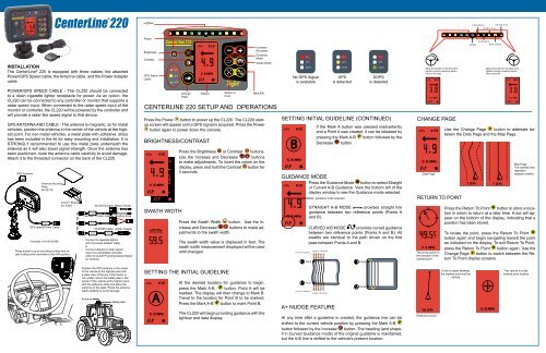
INSTALLATION<br />
The CenterLine ® <strong>220</strong> is equipped with three cables: the attached<br />
Power/GPS Speed cable, the Antenna cable, and the Power Adapter<br />
cable.<br />
Power<br />
Brightness<br />
Contrast<br />
GPS Status<br />
Lights<br />
GPS<br />
GPS<br />
DGPS<br />
10<br />
4.9<br />
5.8 MPH<br />
Increase/<br />
Decrease<br />
Guidance<br />
Mode<br />
Swath Width<br />
GPS<br />
GPS<br />
DGPS<br />
GPS<br />
GPS<br />
DGPS<br />
GPS<br />
GPS<br />
DGPS<br />
lights illuminated on the left of the<br />
lightbar require a steering adjustment<br />
to the right<br />
Center<br />
3.0 ft (.9 m)<br />
6.0 ft (1.8 m)<br />
lights illuminated on the right of the<br />
lightbar require a steering adjustment<br />
to the left<br />
Power/GPS Speed Cable - The CL<strong>220</strong> should be connected<br />
to a clean cigarette lighter receptacle for power. As an option, the<br />
CL<strong>220</strong> can be connected to any controller or monitor that supports a<br />
radar speed input. When connected to the radar speed input of the<br />
monitor or controller, the CL<strong>220</strong> will be powered by the controller and<br />
will provide a radar-like speed signal to that device.<br />
GPS Antenna and Cable - The antenna is magnetic, so for metal<br />
vehicles, position the antenna in the center of the vehicle at the highest<br />
point. For non-metal vehicles, a metal plate with adhesive strips<br />
has been included in the kit for easy mounting and installation. It is<br />
STRONGLY recommended to use this metal plate underneath the<br />
antenna as it will also boost signal strength. Once the antenna has<br />
been positioned, route the antenna cable carefully to avoid damage.<br />
Attach it to the threaded connector on the back of the CL<strong>220</strong>.<br />
GPS Antenna<br />
Antenna Mounting<br />
Plate<br />
65-05179<br />
Speed/Power<br />
Cable<br />
GPS Speed/Power Cable<br />
*included in kit 90-02399<br />
Vecro TM Strips<br />
60-10081<br />
Press suction cup to mounting surface and rotate<br />
locking arms clockwise to the ON position.<br />
Power Cable<br />
45-05478<br />
POWERCABLE<br />
45-054 71<br />
DC: XXXX<br />
Power Cable<br />
45-05458<br />
DC:xx/xx/xx<br />
45-05478 Cable, Battery Power<br />
Connect to<br />
+12v Only<br />
+12v Only<br />
45-05471 Cable, Adapter Weather-Pack<br />
*45-05458 Cable, Lighter Adapter<br />
- Connect to cigarette lighter<br />
with the power adapter cable.<br />
or<br />
- Connect directly to radar speed<br />
input of a compatible controller<br />
(refer to CL<strong>220</strong> Providing Speed Signal<br />
on reverse)<br />
Press the Power button to power up the CL<strong>220</strong>. The CL<strong>220</strong> startup<br />
screen will appear until a GPS signal is acquired. Press the Power<br />
button again to power down the console.<br />
BRIGHTNESS/CONTRAST<br />
SWATH WIDTH<br />
Change<br />
Page<br />
Display<br />
Return to<br />
Point<br />
Mark A/B<br />
CenterLine <strong>220</strong> Setup and Operations<br />
Press the Brightness or Contrast buttons.<br />
Use the Increase and Decrease buttons<br />
to make adjustments. To invert the colors on the<br />
display, press and hold the Contrast button for<br />
3 seconds.<br />
Press the Swath Width button. Use the Increase<br />
and Decrease buttons to make adjustments<br />
to the swath width.<br />
The swath width value is displayed in feet. The<br />
swath width measurement displayed will be used<br />
until changed.<br />
SETTING INITIAL GUIDELINE (CONTINUED)<br />
B<br />
GUIDANCE MODE<br />
Curved A-B Guidance<br />
B Point<br />
If the Mark A button was pressed inadvertently<br />
and a Point A was created, it can be released by<br />
pressing the Mark A-B button followed by the<br />
Decrease button.<br />
Press the Guidance Mode button to select Straight<br />
or Curved A-B Guidance. View the bottom left of the<br />
display window to see the Guidance mode selected.<br />
guidance mode selected<br />
Straight A-B Mode provides straight line<br />
guidance between two reference points (Points A<br />
and B).<br />
CURVED A/B MODE provides curved guidance<br />
between two reference points (Points A and B). All<br />
swaths are identical to the path driven on the first<br />
pass between Points A and B.<br />
Straight A-B Guidance<br />
B Point<br />
CHANGE PAGE<br />
Data Page<br />
RETURN TO POINT<br />
The arrow points in<br />
the direction of the<br />
marked point<br />
Use the Change Page button to alternate between<br />
the Data Page and the Map Page.<br />
Map Page<br />
The dashed lines<br />
represent<br />
adjacent swaths<br />
Press the Return To Point button to store a location<br />
in which to return at a later time. A dot will appear<br />
on the bottom of the display, indicating that a<br />
position has been stored.<br />
To locate the point, press the Return To Point<br />
button again and begin navigating toward the point<br />
as indicated on the display. To exit Return To Point,<br />
press the Return To Point button again. Use the<br />
Change Page button to switch between the Return<br />
To Point display screens.<br />
Position the GPS antenna in the center<br />
of the vehicle at the highest point with<br />
a clear view of the sky. If the tractor is<br />
non-metal, mount the metal plate in the<br />
center of the vehicle at the highest point<br />
with the adhesive strips and place the<br />
antenna on the plate. Route the antenna<br />
cable carefully to avoid damage.<br />
Antenna<br />
Metal plate<br />
SETTING THE INITIAL GUIDELINE<br />
A<br />
At the desired location for guidance to begin,<br />
press the Mark A-B button. Point A will be<br />
marked. The display will then change to Mark B.<br />
Travel to the location for Point B to be marked.<br />
Press the Mark A-B button to mark Point B.<br />
The CL<strong>220</strong> will begin providing guidance with the<br />
lightbar and data display.<br />
A Point<br />
Curved A-B Guidance<br />
Straight A-B Guidance<br />
A+ NUDGE FEATURE<br />
A Point<br />
At any time after a guideline is created, the guidance line can be<br />
shifted to the current vehicle position by pressing the Mark A-B<br />
button followed by the Increase button. The heading (and shape,<br />
if in Curved Guidance mode) of the original guideline is maintained,<br />
but the A-B line is shifted to the vehicle’s present location.<br />
Distance to point<br />
A line is drawn between<br />
the marked point and the<br />
vehicle<br />
The vehicle is at the<br />
marked point location
Curved A-B Mode Detailed Description<br />
Curved A-B mode provides curved guidance between two reference<br />
points - Points A and B. All swaths are identical to the path<br />
driven on the first pass between the initial Points A and B. Guidance<br />
beyond Points A and B will result in Straight Line Guidance.<br />
To optimize curved guidance performance, begin product application<br />
on the longest side of the field and work toward the shorter<br />
side. The following example illustrates the areas that will NOT be<br />
covered by curved guidance when starting on the short side.<br />
CenterLine <strong>220</strong> Providing Speed Signal<br />
The CL<strong>220</strong> can be connected to any controller or monitor that supports<br />
radar speed input. When connected to the radar speed input of<br />
the monitor or controller, the CL<strong>220</strong> may be powered by the controller<br />
and will provide a radar-like speed signal to that device.<br />
Straight A-B Guidance<br />
Curved A-B Guidance<br />
no curved guidance<br />
Mark A<br />
Speed adapter cable required: P/N 45-20042<br />
Radar Speed Calibration # for <strong>TeeJet</strong> Controls: 914<br />
Mark B<br />
Curved A-B Guidance<br />
Straight A-B Guidance<br />
no curved guidance<br />
No adapter required.<br />
Radar Speed Calibration # for Mid-Tech Controls: 1000<br />
Technical Specifications<br />
Electrical:<br />
- Operating temperature -4 o F to +158 o F/-20 o C to +70 o C<br />
- Operating voltage +9VDC to +16VDC<br />
- Operating current < 500mA<br />
Dimensions:<br />
- Enclosure W: 7.125” H: 5.125” D: 1.875”<br />
w: 180.9 mm H: 130.1mm D: 47.6mm<br />
- Display W: 1.42” H: 2.70:<br />
w: 36.0 mm H: 68.5 mm<br />
Speed adapter cable required: P/N 45-20042<br />
Radar Speed Calibration # for 70 Series monitors: 9140<br />
1801 Business Park Drive<br />
Springfield, Illinois 62704 USA<br />
Tel (217) 753-8424<br />
Fax (217) 753-8426<br />
www.teejet.com<br />
Speed adapter cable required: P/N 45-05508<br />
Radar Speed Calibration # for Raven Controls: 730<br />
98-01162 R4