

ULTRA Plus+ 1500 Airless Paint Sprayer - Graco Inc.
ULTRA Plus+ 1500 Airless Paint Sprayer - Graco Inc.
ULTRA Plus+ 1500 Airless Paint Sprayer - Graco Inc.

Create successful ePaper yourself
Turn your PDF publications into a flip-book with our unique Google optimized e-Paper software.
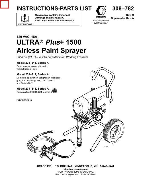
INSTRUCTIONS-PARTS LIST<br />
308–782<br />
INSTRUCTIONS<br />
This manual contains important<br />
warnings and information.<br />
READ AND KEEP FOR REFERENCE.<br />
First choice when<br />
quality counts.<br />
Rev. B<br />
Supercedes Rev. A<br />
120 VAC, 18A<br />
<strong>ULTRA</strong> <strong>Plus+</strong> <strong>1500</strong><br />
<strong>Airless</strong> <strong>Paint</strong> <strong>Sprayer</strong><br />
3000 psi (21.0 MPa, 210 bar) Maximum Working Pressure<br />
Model 231–811, Series A<br />
Basic sprayer on upright cart<br />
without hose or gun<br />
Model 231–812, Series A<br />
Complete sprayer on upright cart with hose,<br />
gun, RAC IV DripLess Tip Guard<br />
and SwitchTip<br />
Model 231–813, Series A<br />
Same as Model 231–811, except<br />
Patents Pending<br />
<br />
GRACO INC. P.O. BOX 1441 MINNEAPOLIS, MN 55440–1441<br />
http://www.graco.com<br />
COPYRIGHT 1996, GRACO INC.<br />
<strong>Graco</strong> <strong>Inc</strong>. is registered to I.S. EN ISO 9001
Warnings . . . . . . . . . . . . . . . . . . . . . . . . . . . . . . . . . . . . . . 2<br />
Setup . . . . . . . . . . . . . . . . . . . . . . . . . . . . . . . . . . . . . . . . . 6<br />
Operation . . . . . . . . . . . . . . . . . . . . . . . . . . . . . . . . . . . . . 7<br />
Flushing . . . . . . . . . . . . . . . . . . . . . . . . . . . . . . . . . . . . . 10<br />
Troubleshooting . . . . . . . . . . . . . . . . . . . . . . . . . . . . . . . 11<br />
Motor Brush Replacement . . . . . . . . . . . . . . . . . . . . . . 13<br />
Removing and Installing Pump . . . . . . . . . . . . . . . . . . 15<br />
Pressure Control . . . . . . . . . . . . . . . . . . . . . . . . . . . . . . 16<br />
Pressure Control Repair . . . . . . . . . . . . . . . . . . . . . . . . 17<br />
Motor . . . . . . . . . . . . . . . . . . . . . . . . . . . . . . . . . . . . . . . . 20<br />
Warning Symbol<br />
WARNING<br />
This symbol alerts you to the possibility of serious<br />
injury or death if you do not follow the instructions.<br />
Table of Contents<br />
Symbols<br />
Bearing Housing & Connecting Rod . . . . . . . . . . . . . 22<br />
Drive Housing Replacement . . . . . . . . . . . . . . . . . . . . 23<br />
<strong>Sprayer</strong> Parts Drawing . . . . . . . . . . . . . . . . . . . . . . . . . 24<br />
<strong>Sprayer</strong> Parts List . . . . . . . . . . . . . . . . . . . . . . . . . . . . . 25<br />
Hose and Gun Parts Drawing and List . . . . . . . . . . . 26<br />
Accessories . . . . . . . . . . . . . . . . . . . . . . . . . . . . . . . . . . 30<br />
Technical Data . . . . . . . . . . . . . . . . . . . . . . . . . . . . . . . . 31<br />
Dimensions . . . . . . . . . . . . . . . . . . . . . . . . . . . . . . . . . . . 31<br />
<strong>Graco</strong> Warranty . . . . . . . . . . . . . . . . . . . . . . . . . . . . . . . 32<br />
<strong>Graco</strong> Phone Number . . . . . . . . . . . . . . . . . . . . . . . . . . 32<br />
Caution Symbol<br />
CAUTION<br />
This symbol alerts you to the possibility of damage to<br />
or destruction of equipment if you do not follow the<br />
instructions.<br />
EQUIPMENT MISUSE HAZARD<br />
WARNING<br />
INSTRUCTIONS<br />
Equipment misuse can cause the equipment to rupture or malfunction and result in serious injury.<br />
<br />
This equipment is for professional use only.<br />
<br />
<br />
<br />
<br />
<br />
<br />
<br />
<br />
<br />
<br />
Read all instruction manuals, tags, and labels before operating the equipment.<br />
Use the equipment only for its intended purpose. If you are uncertain about usage, call your<br />
<strong>Graco</strong> distributor.<br />
Do not alter or modify this equipment. Use only genuine <strong>Graco</strong> parts and accessories.<br />
Check equipment daily. Repair or replace worn or damaged parts immediately.<br />
Do not exceed the maximum working pressure of the lowest rated system component. Refer to<br />
the Technical Data on page 31 for the maximum working pressure of this equipment.<br />
Use fluids and solvents which are compatible with the equipment wetted parts. Refer to the<br />
Technical Data section of all equipment manuals. Read the fluid and solvent manufacturer’s<br />
warnings.<br />
Do not use hoses to pull equipment.<br />
Route hoses away from traffic areas, sharp edges, moving parts, and hot surfaces. Do not expose<br />
<strong>Graco</strong> hoses to temperatures above 180F (82C) or below –40F (–40C).<br />
Do not lift pressurized equipment.<br />
Comply with all applicable local, state, and national fire, electrical, and safety regulations.
WARNING<br />
INJECTION HAZARD<br />
Spray from the gun, leaks or ruptured components can inject fluid into your body and cause extremely<br />
serious injury, including the need for amputation. Fluid splashed in the eyes or on the skin<br />
can also cause serious injury.<br />
<br />
<br />
<br />
<br />
<br />
<br />
<br />
<br />
<br />
<br />
<br />
<br />
<br />
Fluid injected into the skin is a serious injury. The injury may look like just a cut, but it is a serious<br />
injury. Get immediate medical attention.<br />
Do not point the gun at anyone or at any part of the body.<br />
Do not put your hand or fingers over the spray tip.<br />
Do not stop or deflect leaks with your hand, body, glove or rag.<br />
Do not “blow back” fluid; this is not an air spray system.<br />
Always have the tip guard and the trigger guard on the gun when spraying.<br />
Check the gun diffuser operation weekly. Refer to the gun manual.<br />
Be sure the gun trigger safety operates before spraying.<br />
Lock the gun trigger safety when you stop spraying.<br />
Follow the Pressure Relief Procedure on page 7 if the spray tip clogs and before cleaning,<br />
checking or servicing the equipment.<br />
Tighten all fluid connections before operating the equipment.<br />
Check the hoses, tubes, and couplings daily. Replace worn or damaged parts immediately. Do<br />
not repair high pressure couplings; you must replace the entire hose.<br />
Fluid hoses must have spring guards on both ends, to help protect them from rupture caused by<br />
kinks or bends near the couplings.<br />
TOXIC FLUID HAZARD<br />
Hazardous fluid or toxic fumes can cause serious injury or death if splashed in the eyes or on the<br />
skin, inhaled, or swallowed.<br />
<br />
<br />
<br />
Know the specific hazards of the fluid you are using.<br />
Store hazardous fluid in an approved container. Dispose of hazardous fluid according to all local,<br />
state and national guidelines.<br />
Always wear protective eyewear, gloves, clothing and respirator as recommended by the fluid<br />
and solvent manufacturer.
FIRE AND EXPLOSION HAZARD<br />
WARNING<br />
Improper grounding, poor ventilation, open flames or sparks can cause a hazardous condition and<br />
result in a fire or explosion and serious injury.<br />
<br />
<br />
<br />
<br />
<br />
<br />
<br />
<br />
If there is any static sparking or you feel an electric shock while using this equipment, stop<br />
spraying immediately. Do not use the equipment until you identify and correct the problem.<br />
Provide fresh air ventilation to avoid the buildup of flammable fumes from solvents or the fluid<br />
being sprayed.<br />
Keep the spray area free of debris, including solvent, rags, and gasoline.<br />
Electrically disconnect all equipment in the spray area.<br />
Extinguish all open flames or pilot lights in the spray area.<br />
Do not smoke in the spray area.<br />
Do not turn on or off any light switch in the spray area while operating or if fumes are present.<br />
Do not operate a gasoline engine in the spray area.<br />
MOVING PARTS HAZARD<br />
Moving parts can pinch or amputate your fingers.<br />
<br />
<br />
Keep clear of all moving parts when starting or operating the pump.<br />
Before servicing the equipment, follow the Pressure Relief Procedure on page 7 to prevent the<br />
equipment from starting unexpectedly.<br />
NOTE: This is an example of the DANGER label on your sprayer.<br />
This label is available in other languages, free of charge. See page 30 to order.<br />
FIRE AND<br />
EXPLOSION HAZARD<br />
Spray painting, flushing or cleaning equipment with flammable<br />
liquids in confined areas can result in fire or explosion.<br />
Use outdoors or in extremely well ventilated areas. Ground equipment,<br />
hoses, containers and objects being sprayed.<br />
Avoid all ignition sources such as static electricity from plastic drop<br />
cloths, open flames such as pilot lights, hot objects such as cigarettes,<br />
arcs from connecting or disconnecting power cords or turning light<br />
switches on and off.<br />
Failure to follow this warning can result in death or serious injury.<br />
SKIN INJECTION<br />
HAZARD<br />
Liquids can be injected into the body by high pressure airless spray or<br />
leaks – especially hose leaks.<br />
Keep body clear of the nozzle. Never stop leaks with any part of the<br />
body. Drain all pressure before removing parts.Avoid accidental triggering<br />
of gun by always setting safety latch when not spraying.<br />
Never spray without a tip guard.<br />
In case of accidental skin injection, seek immediate<br />
“Surgical Treatment”.<br />
Failure to follow this warning can result in amputation or serious<br />
injury.<br />
READ AND UNDERSTAND ALL LABELS AND INSTRUCTION MANUALS BEFORE USE
Major Components<br />
S<br />
A<br />
K<br />
<br />
M<br />
E<br />
D<br />
F<br />
T<br />
G<br />
U<br />
J<br />
H<br />
P<br />
B<br />
<br />
C<br />
L<br />
R<br />
N<br />
<br />
Fig. 1<br />
A Motor (Under shield shown) DC motor, 120 Vac, 60 Hz, 18A, 1 phase<br />
B Pressure Adjusting Knob Controls fluid outlet pressure<br />
C ON/OFF Switch Power switch that controls 120 Vac power to sprayer<br />
D Drive Assembly Transfers power from DC motor to the displacement pump<br />
E Fluid Filter Filter of fluid between source and spray gun<br />
F Secondary Fluid Outlet Second spray gun operation is connected here<br />
G Pail Hanger Container for fluid to be sprayed may be hung here<br />
H Displacement Pump Pressures fluid to be sprayed through spray gun<br />
J 50 ft. (15 m) Main Hose 1/4 in. ID, grounded, nylon hose with spring guards on both ends<br />
K RAC IV Tip Guard Reverse-A-Clean (RAC) tip guard reduces the risk of fluid injection injury<br />
L Contractor Gun High pressure spray gun with gun safety latch<br />
M RAC IV SwitchTip RAC SwitchTip atomizes fluid and removes clogs from spray tip without<br />
removing tip from spray gun<br />
N 3 ft. (0.9 m) Hose 3/16 in. ID, grounded, nylon hose used between 50 ft. hose and spray gun<br />
to allow more flexibility when spraying<br />
P Pressure Drain Valve Relieves fluid pressure when open<br />
R Pressure Control Controls motor speed to maintain fluid pressure. Works with pressure adjusting<br />
knob.<br />
S Spray Gun Safety Latch Inhibits accidental triggering of spray gun<br />
T Primary Fluid Outlet Hose and spray gun is connected here<br />
U 15/20 Amp Switch Allows sprayer to operate on 15A service with reduced performance
Setup<br />
WARNING<br />
FIRE AND EXPLOSION HAZARD<br />
Proper electrical grounding is essential<br />
to reduce the risk of fire or explosion<br />
which can result in serious injury and<br />
property damage. Also read FIRE OR<br />
EXPLOSION HAZARD on page 4.<br />
1. Connect gun, 3 ft. hose (78) and 50 ft. hose (79).<br />
Don’t install spray tip yet.<br />
2. Two gun hookup. Remove cap (12) from 1/4<br />
npsm(m) secondary hose outlet and attach minimum<br />
50 ft. long hose. For more flexible gun movement,<br />
install 3/16 in. ID, 3 ft. whip hose between<br />
main hose and gun.<br />
WARNING<br />
If you supply your own hoses and spray gun, be<br />
sure the hoses are electrically conductive, that<br />
the gun has a tip guard, and that each part is<br />
rated for at least 3000 psi (21.0 MPa, 210 bar )<br />
Working Pressure. This is to reduce the risk of<br />
serious injury caused by static sparking, fluid<br />
injection or over-pressurization and rupture of<br />
the hose or gun.<br />
CAUTION<br />
To avoid damaging the pressure control, which may<br />
result in poor equipment performance and component<br />
damage, follow these precautions:<br />
1. Always use a nylon spray hose at least 50 ft.<br />
(15 m) long.<br />
2. Never use a wire braid hose as it is too rigid to<br />
act as a pulsation dampener.<br />
3. Never install any shutoff device between the<br />
sprayer outlet (D) and the hose. See Fig. 2.<br />
3. Fill packing nut/wet–cup (E)1/3 full with <strong>Graco</strong><br />
Throat Seal Liquid (TSL), supplied.<br />
4. Check electrical service. Be sure electrical service<br />
is 120 Vac, 60 Hz, 20 A. Use properly grounded<br />
outlet. Do not remove grounding prong of power<br />
supply cord or of any extension cords used. Do not<br />
use an adapter. Extension cords must have 3<br />
wires of minimum 12 gauge size. Long extension<br />
cords reduce sprayer performance. If 20 amp<br />
service is not available, set 15/20 amp switch (C)<br />
to 15 amp to avoid nuisance tripping of circuit<br />
breakers.<br />
5. With ON/OFF switch (A) set to OFF, plug cord into<br />
a grounded electrical outlet located at least 20 ft.<br />
(6 m) away from spray area. See Fig. 2<br />
6. Flush pump to remove lightweight oil which was<br />
left in to protect pump parts after factory testing.<br />
See page 10.<br />
12<br />
C<br />
78<br />
<br />
E<br />
79<br />
<br />
D<br />
<br />
B<br />
55<br />
A<br />
<br />
Do not install any shutoff device here<br />
Fill packing nut 1/3 full with TSL<br />
118<br />
<br />
<br />
Fig. 2
Operation<br />
Pressure Relief Procedure<br />
WARNING<br />
PRESSURIZED EQUIPMENT HAZARD<br />
The system pressure must be manually<br />
relieved to prevent the system from<br />
starting or spraying accidentally. To<br />
reduce the risk of an injury from accidental spray<br />
from the gun, splashing fluid, or moving parts,<br />
follow the Pressure Relief Procedure whenever<br />
you:<br />
are instructed to relieve the pressure,<br />
stop spraying,<br />
check or service any of the system equipment,<br />
or install or clean the spray nozzle.<br />
1. Engage gun safety latch.<br />
2. Turn ON/OFF switch to OFF.<br />
Startup<br />
WARNING<br />
INJECTION HAZARD<br />
To reduce the risk of serious injury,<br />
whenever you are instructed to relieve<br />
pressure, follow the Pressure Relief<br />
Procedure above.<br />
Always use this procedure to help ensure sprayer is<br />
ready to operate and that you start it safely. See<br />
Fig. 2<br />
1. For a first time startup, flush sprayer. See page 10.<br />
2. Close pressure drain valve (118).<br />
3. Don’t install spray tip until pump is primed!<br />
4. Put suction tube into paint container.<br />
5. Lower pressure setting by turning pressure adjusting<br />
knob (B) all the way counterclockwise.<br />
3. Unplug power cord.<br />
4. Disengage gun safety latch. Hold metal part of gun<br />
against grounded metal pail and trigger gun into<br />
pail to relieve pressure.<br />
6. Disengage gun safety latch. See Fig. 3.<br />
<br />
<br />
Gun safety latch<br />
shown engaged<br />
Gun safety latch<br />
shown disengaged<br />
<br />
<br />
5. Engage gun safety latch.<br />
6. Open any fluid drain valves in system. Leave drain<br />
valve open until ready to dispense again.<br />
Fig. 3
Operation<br />
7. To prime pump, hold a metal part of gun firmly<br />
against into a metal waste container. See Fig. 4.<br />
Squeeze trigger and hold it open, turn ON/OFF<br />
switch to ON, and slowly increase pressure setting<br />
until sprayer starts. Keep gun triggered until all air<br />
is forced out of system and paint flows freely from<br />
gun. Release trigger and engage gun safety latch.<br />
CAUTION<br />
Do not run the sprayer dry for more than 30 seconds<br />
to avoid damaging the pump packings.<br />
8. Check all fluid connections for leaks. If any leaks<br />
are found, relieve pressure before tightening<br />
connections.<br />
11. Adjust pressure.<br />
a. Turn pressure adjusting knob clockwise until<br />
spray from gun is just completely atomized. To<br />
avoid excessive overspray and fogging, and to<br />
decrease tip wear and extend life of sprayer,<br />
always use lowest possible pressure needed<br />
to get desired results.<br />
b. If more coverage is needed, use larger tip<br />
rather than increasing pressure.<br />
c. Test spray pattern. To adjust direction of spray<br />
pattern: engage gun safety latch, loosen<br />
retaining nut, position tip guard horizontally for<br />
horizontal pattern or vertically for vertical<br />
pattern then tighten retaining nut.<br />
WARNING<br />
FIRE AND EXPLOSION HAZARD<br />
To reduce the risk of fluids entering<br />
control box, check weep hole (Fig.16, C)<br />
regularly. Replace o–ring when any<br />
leakage is seen. Also read FIRE OR<br />
EXPLOSION HAZARD on page 4.<br />
9. Check weep hole (Fig. 16, C) of pressure control<br />
for leakage at start up and during operation. If<br />
leakage, replace o–ring as instructed in Pressure<br />
Control Transducer and O–Ring Replacement on<br />
page 17.<br />
<br />
Maintain firm metal–to–metal<br />
contact between gun and<br />
grounded pail when flushing<br />
10. Engage gun safety latch. Install spray tip. If you<br />
are using RAC IV tip guard, refer to manual<br />
308–644 for installation instructions.<br />
Fig. 4
Operation<br />
Cleaning a Clogged Tip<br />
WARNING<br />
INJECTION HAZARD<br />
To reduce the risk of serious injury,<br />
whenever you are instructed to relieve<br />
pressure, follow the Pressure Relief<br />
Procedure on page 7.<br />
1. If spray tip clogs, release gun trigger, engage gun<br />
safety latch, and rotate RAC IV handle 180. See<br />
Fig. 5.<br />
2. Disengage gun safety latch and trigger gun into<br />
waste container. Engage gun safety latch again.<br />
3. Return handle to original position. Disengage gun<br />
safety latch and resume spraying.<br />
Shutdown and Care<br />
1. Check packing nut/wet–cup daily. Relieve pressure.<br />
Keep packing nut/wet–cup (A) 1/3 full with<br />
TSL at all times to help prevent fluid buildup on<br />
piston rod and premature wear of packings. Tighten<br />
packing nut just enough to stop leakage. Overtightening<br />
may cause binding and excessive<br />
packing wear. Use screwdriver and light hammer<br />
to adjust nut. See Fig. 6.<br />
2. Clean fluid filter often and whenever sprayer is<br />
stored. First relieve pressure. See manual<br />
307–273 for cleaning procedure.<br />
3. Fill connecting rod cavity with motor oil every 100<br />
hours of operation. Relieve pressure. Remove<br />
front cover. See Fig. 6.<br />
<br />
Fill connecting rod cavity with motor oil after<br />
every 100 hours of operation<br />
<br />
4. If tip is still clogged, engage gun safety latch, shut<br />
off and unplug sprayer, and open pressure drain<br />
valve to relieve pressure. Clean spray tip as shown<br />
in manual 308–644, supplied with RAC IV.<br />
A<br />
<br />
<br />
Tip handle shown in spraying position;<br />
turn handle 180, disengage safety<br />
latch and trigger gun to clear clog.<br />
Trigger safety latch shown engaged.<br />
<br />
<br />
<br />
Fig. 6<br />
Fig. 5<br />
<br />
4. For very short shutoff periods, leave suction tube<br />
in paint, relieve pressure, and clean spray tip.<br />
5. Coil hose and hang it on hose rack when storing,<br />
even overnight, to help protect hose from kinking,<br />
abrasion, coupling damage, etc.
Flushing<br />
When to Flush<br />
1. New <strong>Sprayer</strong>. The sprayer is factory tested with<br />
lightweight oil which is left to protect pump parts.<br />
A<br />
C<br />
Before using water–base paint, flush with mineral<br />
spirits, then warm, soapy water, and then clean<br />
water.<br />
B<br />
<br />
Before using oil–base paint, flush with mineral spirits.<br />
D<br />
2. Changing Colors. Flush with compatible solvent.<br />
3. Changing from water–base to oil–base paint. Flush<br />
with warm, soapy water, then mineral spirits.<br />
4. Changing from oil–base to water–base paint. Flush<br />
with mineral spirits, then warm, soapy water, and<br />
then clean water.<br />
E<br />
Fig. 7<br />
<br />
F<br />
5. Storage. Flush as indicated below, shut off sprayer,<br />
open pressure drain valve to relieve pressure<br />
and leave open.<br />
Water–base paint: flush with water, then mineral<br />
spirits. Leave system filled with mineral spirits.<br />
Oil–base paint: flush with mineral spirits.<br />
CAUTION<br />
Never allow water to freeze in the pressure control.<br />
Doing so prevents the sprayer from being started<br />
and causes serious damage to the pressure control.<br />
Push the water out with mineral spirits.<br />
6. Startup after storage. Before using water–base<br />
paint, flush out mineral spirits with soapy water and<br />
then clean water. When using oil–base paint, flush<br />
out mineral spirits with the paint to be sprayed.<br />
How to Flush<br />
1. Relieve pressure.<br />
2. Remove filter bowl (C) and screen (D). Install<br />
bowl (C) and filter support (E) without screen (D)<br />
to flush. See Fig. 7.<br />
3. Close pressure drain valve (F).<br />
4. Pour 1/2 gallon of compatible solvent into grounded<br />
metal pail. Put suction tube in pail.<br />
5. Remove spray tip from gun.<br />
<br />
6. Turn pressure adjusting knob (A) completely<br />
counterclockwise to lowest pressure setting.<br />
WARNING<br />
FIRE AND EXPLOSION HAZARD<br />
To reduce static sparking and splashing,<br />
always remove the spray tip from<br />
the gun, and hold a metal part of the<br />
gun firmly to the side of a grounded metal pail<br />
when flushing.<br />
7. Hold metal part of gun firmly against metal waste<br />
container. See Fig. 4. Trigger gun, turn sprayer<br />
switch (B) on, and slowly increase pressure until<br />
sprayer just starts. Keep gun triggered until all air<br />
is forced out of system and solvent flows freely<br />
from gun. Release trigger and engage gun safety<br />
latch.<br />
NOTE: If the pump is hard to prime, open the drain<br />
valve. When fluid comes from the valve, close it.<br />
Proceed as in Step 7.<br />
8. Remove suction tube from pail. Disengage gun<br />
safety latch and trigger gun to force solvent from<br />
hose. Do not run pump dry for more than 30<br />
seconds to avoid damaging pump packings!<br />
Relieve pressure.<br />
9. Leave pressure drain valve (F) open until sprayer<br />
is used again.<br />
10. Clean filter screen (D) and reinstall. Reinstall<br />
bowl (C), hand tight only.<br />
11. If pump is flushed with mineral spirits and is to be<br />
used with water–base paint, flush with soapy water<br />
and then clean water. Relieve pressure.
Troubleshooting<br />
WARNING<br />
INJECTION HAZARD<br />
To reduce the risk of serious injury, whenever you are instructed to relieve pressure, follow the<br />
Pressure Relief Procedure on page 7.<br />
Check everything in the guide before disassembling the sprayer.<br />
TYPE OF PROBLEM<br />
Building circuit breaker opens<br />
<strong>Sprayer</strong> will not run<br />
WHAT TO CHECK<br />
If check is OK, go to next check<br />
Check all electrical wiring for damaged<br />
insulation.<br />
Check for other electrical appliances on<br />
circuit.<br />
Check position of 15–20 (Lo–High) amp<br />
switch.<br />
Check pressure control knob setting. Motor<br />
will not run if it is at minimum setting (fully<br />
counterclockwise).<br />
Check for a clogged spray tip. Refer to<br />
separate gun or tip instruction manual.<br />
Check extension cord for visible damage.<br />
Use a volt meter or test lamp at extension<br />
cord outlet to check.<br />
Check sprayer power supply cord for visible<br />
damage such as broken insulation or wires.<br />
Check electrical supply with volt meter. Meter<br />
should read 105–125 VAC.<br />
Check for motor damage. Remove drive<br />
housing assembly. See page 17. Try to rotate<br />
fan by hand.<br />
Check for locked motor rotor. Unplug cord<br />
and try to turn fan blades with a screwdriver.<br />
Check for shorted motor. Use ohmmeter to<br />
check for shorts between motor leads or<br />
between motor leads and motor frame.<br />
WHAT TO DO<br />
When check is not OK refer to this column<br />
Replace any damaged wiring.<br />
Shutdown other electrical appliances on<br />
circuit.<br />
Put switch in 15 amp (LO) position.<br />
Slowly increase pressure setting to see if<br />
motor starts.<br />
Relieve pressure. Refer to separate gun or<br />
tip instruction manual for tip cleaning.<br />
Replace extension cord.<br />
Replace power supply cord.<br />
Reset building circuit breaker; replace<br />
building fuse. Try another outlet.<br />
Replace motor (1) if fan won’t turn.<br />
Repair gear train or pump, if damaged. Thaw<br />
the sprayer, if frozen; See NOTE 1. Replace<br />
the pressure control, if damaged.<br />
Inspect for damage to motor brush leads.<br />
Replace motor, if necessary.<br />
Defective pressure control transducer.<br />
Replace pressure control transducer. See<br />
page 17.<br />
Poor spray pattern Check for worn spray tip. Relieve pressure and then replace the tip.<br />
See the separate gun or tip manual.
Troubleshooting<br />
TYPE OF PROBLEM<br />
Motor runs and pump strokes,<br />
but output is low or there is no<br />
output.<br />
WHAT TO CHECK<br />
If check is OK, go to next check<br />
WHAT TO DO<br />
When check is not OK refer to this column<br />
Check extension cord size and length. Replace cord with a larger size, grounding<br />
type extension cord.<br />
Motor runs but pump does not<br />
stroke.<br />
Motor is hot and runs<br />
intermittently.<br />
Check paint supply.<br />
Check for clogged intake strainer.<br />
Check for loose suction tube or loose fittings.<br />
Check for worn spray tip.<br />
Check motor brushes; check for loose leads<br />
and terminals, minimum 13 mm brush length,<br />
broken or misaligned springs, or brushes<br />
binding in holders. See page 13.<br />
Check motor armature for shorts by using an<br />
armature tester (growler).<br />
Check to see if pump continues to stroke<br />
when gun trigger is released. With pump on<br />
and primed, trigger gun momentarily, then<br />
release and engage safety latch. Relieve<br />
pressure, turn off and unplug sprayer.<br />
Check to see if intake valve ball and piston<br />
ball are seating properly.<br />
Check for leaking around throat packing nut<br />
which may indicated worn or damaged<br />
packings.<br />
Defective pressure control transducer.<br />
Check displacement pump connecting rod<br />
pin (20). See page 15.<br />
Check for frozen or hardened paint in the<br />
pump (39).<br />
Be sure crank in drive housing rotates; plug<br />
in sprayer and turn on briefly to check. Turn<br />
off and unplug sprayer.<br />
Determine if sprayer was operated at high<br />
pressure with small tips, which causes low<br />
motor RPM and excessive heat build up.<br />
Be sure ambient temperature where sprayer<br />
is located is no more than 90F and sprayer<br />
is not located in direct sun.<br />
Determine in sprayer was turned on,<br />
pressurized, but not operating for long<br />
periods of time.<br />
Refill and reprime pump.<br />
Remove and clean strainer and reinstall.<br />
Tighten; use thread sealant or sealing tape on<br />
threads, if necessary.<br />
Follow Pressure Relief Procedure<br />
Warning, then replace tip. See your<br />
separate gun or tip manual.<br />
Replace parts as needed. See page 13.<br />
Replace motor. See page 20.<br />
Service pump. See manual 307–806.<br />
Remove intake valve and clean. Check balls<br />
and seats for nicks; replace if necessary.<br />
See manual 307–806. Strain paint before<br />
using to remove particles that could clog the<br />
pump.<br />
Replace packings. See manual 307–806.<br />
Also check piston valve seat for hardened<br />
paint or nicks and replace if necessary.<br />
Tighten the packing nut/wetcup.<br />
Replace pressure control transducer. See<br />
page 17.<br />
Replace pin, if missing. Be sure retainer<br />
spring (35) is fully in groove all around<br />
connecting rod. See page 15.<br />
Thaw. See NOTE 1. Plug in sprayer and turn<br />
on. Slowly increase pressure setting to see if<br />
motor starts.<br />
Check drive housing assembly for damage<br />
and replace if necessary. See page 23.<br />
Decrease pressure setting or increase tip<br />
size.<br />
Move sprayer to shaded, cooler area, if<br />
possible.<br />
Turn off sprayer whenever you stop spraying<br />
for a while and relieve fluid pressure.<br />
NOTE 1: Thaw the sprayer if water or water–based paint has frozen in it, by placing it in a warm area. Do not try to<br />
start the sprayer until it has thawed completely. If paint hardened (dried) in the sprayer, replace the pump packings.<br />
See manual 307–806.
-Motor Brush Replacement<br />
ELECTRIC SHOCK HAZARD<br />
To reduce the risk of Electric Shock: wait<br />
5 minutes after turning sprayer off before<br />
servicing to allow stored current to discharge.<br />
WARNING<br />
NOTE: Replace the brushes when they have worn to<br />
less than 0.4 in. See Fig. 10. Always replace both<br />
brushes at the same time. A Brush Repair Kit, p/n<br />
220–853, and spring clip, p/n 110–816, are available.<br />
NOTE: To maximize replacement brush life, break in new<br />
brushes by operating the sprayer with no load for at least<br />
one hour. To operate with no load, remove the pump<br />
connecting rod pin.<br />
WARNING<br />
INJECTION HAZARD<br />
To reduce the risk of serious injury,<br />
whenever you are instructed to relieve<br />
pressure, follow the Pressure Relief<br />
Procedure on page 7.<br />
Fig. 8<br />
A<br />
14<br />
1. Remove motor cover (14) and both inspection<br />
covers (A). See Fig. 8.<br />
<br />
2. Push in spring clip (D) to unhook, and then pull<br />
out. See Fig. 9.<br />
3. Loosen terminal screw (F). Pull brush lead (E)<br />
away, leaving motor lead (G) in place. Remove<br />
brush (C) and spring (B). See Fig. 10.<br />
4. Inspect commutator for excessive pitting, burning<br />
or gouging. A black color on commutator is normal.<br />
Have commutator resurfaced by qualified motor<br />
repair shop if brushes seem to wear too fast.<br />
5. Install new brush (C) so lead is in long slot (H) of<br />
holder. See Fig. 11. Slide the terminal (E) under<br />
the terminal screw washer. Make sure motor<br />
lead (G) is still connected the at screw. Tighten<br />
screw (F). See Fig. 10.<br />
6. Place spring (B) on brush as shown in Fig. 11.<br />
Spring must coil as shown.<br />
7. Push in and hook spring clip (D). See Fig. 11.<br />
8. Repeat for other side.<br />
9. Test brushes. Remove connecting rod pin (20).<br />
See Fig. 13, page 15. With sprayer off, turn pressure<br />
control knob fully counterclockwise to minimum<br />
pressure. Plug in sprayer. Turn sprayer on.<br />
Slowly increase pressure until motor is at full<br />
speed. Inspect brush and commutator contact<br />
area for excessive arcing. Arcs should not “trail” or<br />
circle around commutator surface.<br />
CAUTION<br />
Do not touch the brushes, leads, springs or brush<br />
holders while the sprayer is plugged in, to reduce the<br />
risk of electric shock and serious bodily injury.<br />
10. Install brush inspection plates, gaskets, and covers.<br />
11. Break in brushes. Operate sprayer for at least one<br />
hour with no load. Then reinstall connecting rod<br />
pin (20).
-Motor Brush Replacement<br />
B<br />
<br />
H<br />
B<br />
<br />
C<br />
<br />
Order part no. 110–816<br />
C<br />
D<br />
Hook of spring clip<br />
Fig. 9<br />
D <br />
<br />
<br />
Spring must<br />
coil in this<br />
direction<br />
B<br />
D<br />
Fig. 11<br />
<br />
C<br />
<br />
<br />
Fig. 10<br />
0.4 in. minimum<br />
G<br />
E<br />
F
Removing and Installing Pump<br />
WARNING<br />
INJECTION HAZARD<br />
To reduce the risk of serious injury,<br />
whenever you are instructed to relieve<br />
pressure, follow the Pressure Relief<br />
Procedure on page 7.<br />
Removal See Fig. 12.<br />
1. Flush pump, if possible. Relieve pressure again.<br />
Stop pump with piston rod in lowest position, if<br />
possible.<br />
CAUTION<br />
If the locknut (38) loosens during operation, the<br />
threads of the bearing housing (27) will be damaged.<br />
Be sure to tighten the locknut firmly.<br />
3. Tighten packing nut/ wet-cup just enough to stop<br />
leakage, but no tighter. Fill wet–cup/packing nut<br />
1/3 full with <strong>Graco</strong> TSL.<br />
2. Disconnect drain tube (101) from pump (39) and<br />
suction tube (42).<br />
3. Remove suction tube (42); hold wrench on pump<br />
intake valve (223) to keep pump from loosening.<br />
4. Remove hose (47).<br />
5. Push retaining spring (35) up and push out<br />
pin (20).<br />
6. Loosen locknut (38) and unscrew pump from<br />
bearing housing (27).<br />
Installation See Fig. 12 and 13.<br />
1. Screw displacement pump into bearing<br />
housing (27) until pin hole in connecting rod assembly<br />
(29) and displacement rod (A) align. Install<br />
pin (20).<br />
27<br />
35<br />
A<br />
20<br />
38<br />
101<br />
Fig. 12<br />
<br />
47<br />
39<br />
223<br />
42<br />
2. Continue to screw pump into bearing housing until<br />
top threads of pump cylinder are flush with face of<br />
bearing housing and outlet nipple (75) is straight<br />
back. Push retaining spring (35) into groove<br />
around connecting rod. Tighten locknut (38) to 70<br />
ft-lb (95 N.m).<br />
<br />
<br />
Face of bearing housing<br />
Torque to 70 ft–lb (95 N.m)<br />
WARNING<br />
MOVING PARTS HAZARD<br />
Be sure the retaining spring (35) is firmly<br />
in the groove of the connecting rod, all<br />
the way around, to prevent it from working<br />
loose due to vibration.<br />
<br />
29<br />
35<br />
27<br />
20<br />
If the pin works loose, it or other parts could break<br />
off due to the force of the pumping action. These<br />
parts could be projected through the air and result<br />
in serious bodily injury or property damage, including<br />
damage to the pump, connecting rod or bearing<br />
housing.<br />
Fig. 13<br />
75<br />
38
Pressure Control<br />
CAUTION<br />
Do not install the pressure control until motor is<br />
checked. A defective motor may damage the pressure<br />
control. Make sure to test the motor prior to<br />
pressure control installation.<br />
ELECTRIC SHOCK HAZARD<br />
To reduce the risk of Electric Shock: wait<br />
5 minutes after turning sprayer off before<br />
servicing to allow stored current to discharge.<br />
Motor Test<br />
WARNING<br />
With motor shield off and four motor leads disconnected:<br />
<br />
Check continuity with multimeter from each black<br />
motor lead to ground (one at a time). Any reading<br />
less than infinite resistance – even very high resistance<br />
– means motor is shorted to ground. Replace<br />
motor.<br />
CAUTION<br />
A motor that is shorted to ground will damage the<br />
pressure control.<br />
2. Remove fan cover from motor.<br />
3. Remove pump pin ( See page 15 for instructions to<br />
remove pin).<br />
4. With black motor leads not connected, use motor<br />
fan to spin motor quickly. Motor should spin freely<br />
in both directions. If not, replace motor.<br />
5. Connect black motor leads together.<br />
8. Install pump pin and fan cover.<br />
WARNING<br />
INJECTION HAZARD<br />
To reduce the risk of serious injury,<br />
whenever you are instructed to relieve<br />
pressure, follow the Pressure Relief<br />
Procedure on page 7.<br />
1. Relieve pressure.<br />
2. Remove ten screws (64) and motor shield (14).<br />
See Fig. 15 and parts list, except as noted.<br />
3. Loosen outlet cover on pressure control wiring<br />
box. Disconnect motor leads. See Fig 14.<br />
4. Loosen black conduit (22) from pressure control<br />
fitting and pull out wires<br />
5. Remove hose (47) from rear of pressure control<br />
(116).<br />
6. Remove hose (121) and 45 swivel union (119)<br />
from front of pressure control (116).<br />
7. Support pressure control (116) and carefully remove<br />
motor mount screws (37). Remove pressure<br />
control.<br />
8. Install new pressure control (116) with screws (37).<br />
9. Continue to assemble sprayer.<br />
Black/White<br />
Black/<br />
White<br />
6. Use motor fan to turn motor. It should be much<br />
harder to turn than in step 4. If there is uneven or<br />
no resistance to turning, check brushes and replace<br />
if necessary.<br />
7. If there is still uneven or no resistance to turning,<br />
replace motor.<br />
Fig 14<br />
Red<br />
Yellow
Pressure Control<br />
14<br />
64<br />
37<br />
<br />
22,93<br />
116<br />
47<br />
120<br />
<br />
Seals (93) located inside conduit (22)<br />
121<br />
119<br />
47<br />
<br />
Fig 15<br />
Pressure Control Repair<br />
General Repair and Replacement<br />
WARNING<br />
INJECTION HAZARD<br />
To reduce the risk of serious injury,<br />
whenever you are instructed to relieve<br />
pressure, follow the Pressure Relief<br />
Procedure on page 7.<br />
1. Relieve pressure.<br />
2. Remove power cord (23) and plug retainer (23a)<br />
by removing screws (230) and washers (229).<br />
3. Remove screws (213) and lockwashers (214).<br />
Carefully remove control housing (202) from<br />
control motor board (201) so internal wiring is not<br />
damaged. Lay housing on side next to control<br />
motor board. See Fig. 16 and parts list.<br />
4. Remove and replace only those components and<br />
wires necessary for repair. Make a diagram showing<br />
wire hook–ups for items removed to insure<br />
correct wiring when reinstalling. See Fig 17 for<br />
wiring information.<br />
5. Install control housing (202) to motor control<br />
board (201) using screws (213) and<br />
lockwashers (214).<br />
Pressure Control Transducer and O–Ring<br />
Replacement<br />
WARNING<br />
FIRE AND EXPLOSION HAZARD<br />
Proper O–ring replacement is essential<br />
to reduce the risk of fire or explosion<br />
which can result in serious injury and<br />
property damage. Also read FIRE OR<br />
EXPLOSION HAZARD on page 4.<br />
NOTE: Do not replace o–ring unless damaged or if<br />
leakage is seen around weep hole, o–ring or<br />
transducer.<br />
1. See Fig. 16 and pressure control part list. Disassemble<br />
pressure control as in steps 1 through 4 on<br />
page 17 and remove old transducer (219) and, if<br />
necessary, old o–ring (220).
Pressure Control Repair<br />
229<br />
230<br />
23<br />
23a<br />
202<br />
214<br />
213 <br />
216<br />
215<br />
217<br />
218<br />
219<br />
A<br />
220<br />
B<br />
213<br />
214<br />
C<br />
<br />
201<br />
<br />
Torque to 150 in. lbs (17 N–m)<br />
Fig 16<br />
2. Carefully slide new o–ring (220) down bore (A) of<br />
motor control (201) into o–ring groove (B). Make<br />
sure o–ring is in groove around its entire circumference.<br />
NOTE: O–ring (220) is made of<br />
PTFE which is more<br />
difficult to work with.<br />
3. Carefully slide new transducer and plastic<br />
spacer (217) down bore. Loosely attach<br />
bracket (218), screws (213), and washers (214).<br />
4. Seat transducer into o–ring by drawing down<br />
screws and washers until bracket is flush with<br />
motor control surface.<br />
<br />
5. Carefully remove transducer and verify that o–ring<br />
is seated correctly and not pushed out of groove. If<br />
not seated correctly use new o–ring and repeat<br />
steps 2 through 5.<br />
6. When o–ring is correctly installed, reinstall transducer<br />
and tighten screws to 150 in. lbs (17 N–m).<br />
Install spacer (216) and C–clip (215). Re–connect<br />
electrical lead and re–assemble sprayer.<br />
7. Follow Operation Startup procedures for sprayer<br />
on page 7 using compatible fluid.<br />
8. Inspect weep hole (C) for any leakage.<br />
9. If any leakage is present, replace o–ring repeating<br />
steps 1 through 9.
Pressure Control Wiring<br />
GRN/YEL wire, E to housing ground<br />
Twisted pair<br />
Housing ground<br />
4 5 6<br />
E<br />
L<br />
N<br />
BLACK wire, L to on/off sw–1<br />
WHITE wire, N to on/off sw–4<br />
On/off sw<br />
WHITE<br />
wire on/off<br />
SW–5 to<br />
to L2 on<br />
board<br />
1 2<br />
3<br />
Red wires to I1<br />
and I2 on board<br />
Twisted pair<br />
<br />
BLACK<br />
wire on/off<br />
SW–2 to<br />
to L1 on<br />
board<br />
To J3<br />
Twisted pair<br />
From control housing,<br />
one red wire to I1<br />
From control<br />
housing, WHITE<br />
wire to L2<br />
From control housing,<br />
one red wire to I2<br />
I1<br />
L2<br />
L1<br />
From control<br />
housing, BLACK<br />
wire to L1<br />
Connector from<br />
potentiometer to J3<br />
I2<br />
J3<br />
J7<br />
Twisted pair<br />
J5 J4<br />
J6<br />
GND<br />
<br />
<br />
Ground wire to<br />
housing ground<br />
Wires J4/J5 to<br />
15/20 switch<br />
Connector from pressure<br />
transducer to J6<br />
Fig 17
Motor<br />
WARNING<br />
INJECTION HAZARD<br />
To reduce the risk of serious injury,<br />
whenever you are instructed to relieve<br />
pressure, follow the Pressure Relief<br />
Procedure on page 7.<br />
ELECTRIC SHOCK HAZARD<br />
To reduce the risk of Electric Shock: wait<br />
5 minutes after turning sprayer off before<br />
servicing to allow stored current to discharge.<br />
WARNING<br />
NOTE: Refer to Fig. 18 and parts list, except as<br />
noted.<br />
1. Relieve pressure.<br />
2. Remove motor shield (14). Remove front cover<br />
(31). Disconnect hose (47) at pump. Disconnect<br />
drain hose (101) from pump (39).<br />
3. Remove outlet cover on pressure control wiring<br />
box. Disconnect four motor leads. See Fig 14.<br />
4. Unscrew conduit connector (125) from motor and<br />
pull motor leads from conduit (22).<br />
5. Remove screws (51) from recess of drive housing.<br />
6. Remove screws (21 and 30) from motor bell (F).<br />
7. Use a plastic mallet to tap displacement pump (39)<br />
from rear to loosen drive housing (18) from motor<br />
bell (F). Pull off drive housing.<br />
NOTE: To avoid damage to the drive housing: Do not<br />
drop the gear cluster (9), which may stay engaged in the<br />
motor bell or in the drive housing. Do not lose the thrust<br />
balls (10) or drop them between gears. The balls usually<br />
stay in the shaft recesses, but could be dislodged. If the<br />
balls are not in place, the bearings wear prematurely.<br />
8. Lower pressure control (116) by unscrewing motor<br />
mounting screws (37).<br />
9. Lift off motor (1).<br />
10. Mount and center new motor on frame and attach<br />
pressure control (116) with motor mounting<br />
screws (37).<br />
11. Insert motor leads through connector (125) and<br />
conduit (22) to pressure control. Screw connector<br />
(125) two or three threads into motor. Tighten<br />
locknut up to motor. Connect four motor leads.<br />
See Fig. 14.<br />
12. Liberally grease gear cluster (9) and pinion gear<br />
(G) and pack all bearings in motor bell. Be sure<br />
thrust balls (10) are in place. (One ball is included<br />
with a replacement drive housing.)<br />
13. Place bronze–colored washer (18b) and then<br />
silver–colored washer (18a) on shaft protruding<br />
from big gear in drive housing (18).<br />
14. Align gears and push drive housing (18) straight<br />
onto motor bell (F) and locating pins.<br />
15. Continue to reassemble sprayer.
Seals (93) located inside conduit (22)<br />
Bronze colored washer<br />
Apply 6 ounces bearing grease<br />
Silver colored washer<br />
<br />
G<br />
F<br />
1<br />
21<br />
37<br />
14<br />
<br />
18<br />
18b 9<br />
18a 10<br />
10<br />
125<br />
31<br />
22<br />
<br />
101<br />
Fig. 18<br />
39<br />
51<br />
47<br />
30
Bearing Housing and Connecting Rod<br />
WARNING<br />
INJECTION HAZARD<br />
To reduce the risk of serious injury,<br />
whenever you are instructed to relieve<br />
pressure, follow the Pressure Relief<br />
Procedure on page 7.<br />
NOTE: Stop the sprayer at the bottom of its stroke to<br />
get the crank (H) in its lowest position.To lower the<br />
crank manually, rotate the blades of the motor fan with<br />
a screwdriver.<br />
1. Remove pump. See page 15.<br />
2. Remove front cover (31). Remove bearing housing<br />
screws (33).<br />
<br />
31<br />
Torque to<br />
300 in–lb<br />
(34 N.m)<br />
<br />
33<br />
29<br />
K<br />
J<br />
H<br />
18<br />
3. Tap lower rear of bearing housing (27) with a<br />
plastic mallet to loosen it from drive housing (18).<br />
Pull bearing housing and connecting rod (29)<br />
straight off drive housing.<br />
4. Remove pail bracket assembly (L) and reinstall it<br />
on new bearing housing.<br />
5. Inspect crank (H) for excessive wear and replace<br />
parts as needed.<br />
27<br />
6. Evenly lubricate inside of bronze bearing (K) with<br />
motor oil. Liberally pack roller bearing (J) with<br />
bearing grease.<br />
7. Assemble connecting rod (29) and bearing housing<br />
(27).<br />
8. Clean mating surfaces of bearing and drive housings.<br />
<br />
9. Align connecting rod with crank (H) and align<br />
locating pins in drive housing with holes in bearing<br />
housing (27). Push bearing housing onto drive<br />
housing or tap it into place with a plastic mallet.<br />
Fig. 19<br />
10. Install bearing housing screws (33). Torque evenly<br />
to 300 in–lb (34 N.m).<br />
11. Reinstall all parts. See page 15 to install pump.
Drive Housing Replacement<br />
WARNING<br />
INJECTION HAZARD<br />
To reduce the risk of serious injury,<br />
whenever you are instructed to relieve<br />
pressure, follow the Pressure Relief<br />
Procedure on page 7.<br />
NOTE: Stop the sprayer at the bottom of its stroke to<br />
get the crank (H) in its lowest position. To lower it<br />
manually, carefully rotate the blades of the fan with a<br />
screwdriver.<br />
1. Remove front cover (31). Remove motor shield<br />
(14).<br />
2. Disconnect pump outlet hose (47).<br />
3. Remove screws (33) from bearing housing.<br />
4. Lightly tap lower rear of bearing housing (27) with a<br />
plastic mallet to loosen it from drive housing (18). Pull<br />
bearing housing and connecting rod assembly<br />
straight off drive housing.<br />
5. Remove screws (51) from recess of drive housing.<br />
6. Remove screws (30 and 21) from motor bell (F).<br />
7. Tap drive housing (18) with a plastic mallet to loosen<br />
from motor bell, then pull straight off.<br />
NOTE: To avoid damage to the drive housing:<br />
Do not drop the gear cluster (9), which may stay<br />
engaged in the motor bell or in the drive housing.<br />
Do not lose the thrust balls (10) or drop them between<br />
gears. The balls usually stay in the shaft recesses, but<br />
could be dislodged. If the balls are not in place, the<br />
bearings will wear prematurely.<br />
8. Use approximately 6 oz. of bearing grease<br />
supplied with drive housing replacement kit to<br />
grease gear cluster (9). Check to be sure thrust<br />
balls (10) are in place.<br />
9. Place bronze–colored washer (18b) and then silver–<br />
colored washer (18a) on shaft protruding from big<br />
gear in drive housing (18).<br />
10. Align gears and push new drive housing straight<br />
onto motor bell and locating pins.<br />
11. Continue to reassemble sprayer. Torque screws<br />
(33) to 300 in–lb (34 N.m).<br />
14<br />
<br />
Torque to 300 in–lb (34 N.m)<br />
21<br />
<br />
Bronze color<br />
F<br />
<br />
Apply 6 ounces bearing grease to this gear<br />
<br />
18a<br />
<br />
Silver color<br />
<br />
9<br />
H<br />
18 18b<br />
<br />
27<br />
31<br />
<br />
33<br />
10<br />
30<br />
51<br />
47<br />
Fig. 20
<strong>Sprayer</strong> Parts Drawing<br />
18<br />
18b 9 18a<br />
10<br />
10<br />
61<br />
3,98 <br />
134 <br />
(both sides)<br />
29<br />
2<br />
<br />
32<br />
<br />
4<br />
31<br />
19<br />
49<br />
33<br />
38<br />
20<br />
39<br />
27<br />
35<br />
69<br />
51<br />
119<br />
75<br />
47<br />
<br />
1 64<br />
21<br />
63<br />
63<br />
22<br />
30<br />
63<br />
97<br />
14<br />
37<br />
64<br />
81<br />
82<br />
64<br />
91<br />
Ref<br />
61<br />
62<br />
17<br />
83<br />
52<br />
80<br />
Ref 6<br />
100<br />
121<br />
37<br />
<br />
<br />
102<br />
Safety label<br />
Identification label<br />
42<br />
119<br />
116<br />
134<br />
<br />
6<br />
60<br />
<br />
<br />
Information label<br />
Caution label<br />
7<br />
85<br />
125<br />
23a<br />
23<br />
Ref<br />
47<br />
120 101<br />
54<br />
22,93<br />
53<br />
121<br />
48<br />
122<br />
26<br />
34<br />
46<br />
46<br />
118 12<br />
126<br />
95<br />
<br />
37<br />
58<br />
11
Models 231–811, Series A; 231–812, Series A; and<br />
231–813, Series A (items 1–134)<br />
NOTE: Models 231–811 and 231–813 do not include:<br />
Items 25, 55, 78, and 79 shown on page 26.<br />
<strong>Sprayer</strong> Parts List<br />
Ref<br />
No. Part No. Description Qty<br />
1 220–854 MOTOR KIT 1<br />
2 290–058 LABEL, identification, motor cover 1<br />
3 290–059 LABEL, identification, motor cover 1<br />
4 290–057 LABEL, identification, front cover 1<br />
6 220–636 CART 1<br />
7 181–072 STRAINER 1<br />
9 220–637 GEAR REDUCER 1<br />
10 100–069 BALL, steel; 1/4” dia. 1<br />
11 104–811 HUBCAP 2<br />
12 220–285 CAP 1<br />
14 223–153 MOTOR SHIELD KIT 1<br />
17 111–590 BUTTON, snap 2<br />
18 220–879 DRIVE HOUSING KIT<br />
<strong>Inc</strong>ludes items 18 a and 18b,<br />
and one of item 10 1<br />
18a 183–209 .BEARING, thrust 1<br />
18b 106–227 .SPACER 1<br />
19 189–918 HANGER, pail 1<br />
20 183–210 PIN, straight, 3/8 x 1–1/8” 1<br />
21 100–644 SCREW, soc head, no. 1/4–20 x 3/4” 2<br />
22 065–312 CONDUIT, electrical<br />
specify length when ordering: 5.5 in.<br />
23 239–749 CORD, power (for models 231–811 1<br />
and 231–812<br />
239–771 CORD, power (for model 231–813) 1<br />
23a 192–149 PLUG, Retainer (part of 23) 1<br />
24 107–264 TERMINAL, female (not shown) 2<br />
26 154–636 WASHER 2<br />
27 220–639 BEARING HOUSING KIT 1<br />
29 220–640 CONNECTING ROD KIT 1<br />
30 100–643 SCREW, socket head, no. 1/4–20 x 1” 2<br />
31 183–168 COVER, housing 1<br />
32 108–850 SCREW, mach, filh; no. 8–32 x 1–1/4” 4<br />
33 110–141 CAPSCREW, sch; 3/8–16 x 1–1/5” 4<br />
34 100–840 ELBOW 1<br />
35 183–169 SPRING, retaining 1<br />
37 110–963 CAPSCREW, flange head,<br />
5/16–18 x 3/4” 6<br />
38 189–969 NUT, HEX, 1 13/16 unc–2b 1<br />
39 220–872 DISPLACEMENT PUMP<br />
see manual 307–806 1<br />
42 183–423 TUBE, INTAKE 1<br />
46 162–453 NIPPLE, hex; 1/4 npsm x 1/4 npt,<br />
1–3/16” long 2<br />
47 235–542 HOSE, 3/8 npsm(f) x 14–1/2” 1<br />
Ref.<br />
No. Part No. Description Qty.<br />
48 214–570 FLUID FILTER<br />
see manual 307–273 for parts<br />
includes one of items 46 and 85 1<br />
49 106–115 LOCKWASHER, spring; 3/8” 4<br />
51 108–849 CAPSCREW, sch; 1/4–20 x 3” 2<br />
52 110–243 RING, retaining 2<br />
53 108–691 PLUG, tubing 2<br />
54 108–460 CONNECTOR 1<br />
57 178–034 TAG, WARNING (not shown) 1<br />
58 101–242 RING, retaining 2<br />
59 206–994 THROAT SEAL LIQUID, 0.27 liter 1<br />
60 179–811 WHEEL 2<br />
61 220–633 HANDLE, cart 1<br />
62 192–027 SLEEVE, cart handle 2<br />
63 105–510 LOCKWASHER, spring, 1/4” 6<br />
64 108–865 SCREW, mach, pnh; 8–32 x 3/8” 10<br />
69 112–746 NUT, retainer 2<br />
75 183–461 ADAPTER; 3/8 npsm x 1/4 npt 1<br />
80 109–032 SCREW, mach, pnh; 10–24 x 1/4” 4<br />
81 185–384 BRACKET 2<br />
82 110–240 NUT 2<br />
83 183–350 WASHER, flat; 7/8” ID 2<br />
85 100–040 PLUG 1<br />
91 100–020 LOCKWASHER, .194” ID 2<br />
93 107–447 SEAL 2<br />
95 183–466 LABEL, Caution 1<br />
97 185–951 LABEL, WARNING 1<br />
98 185–952 LABEL, WARNING 1<br />
100 186–490 CLIP, spring 1<br />
101 190–339 TUBE, drain 1<br />
102 181–102 CLIP, spring 1<br />
116 239–750 PRESSURE CONTROL KIT 1<br />
See Parts List on page 29<br />
118 239–279 PRESSURE DRAIN VALVE 1<br />
119 161–889 UNION, swivel 2<br />
120 156–849 NIPPLE, pipe 1<br />
121 239–278 HOSE, high pressure, 12 in. 1<br />
122 192–135 BRACKET, filter 1<br />
124 111–040 LOCKNUT, nylon, 5/16–18 2<br />
125 110–138 CONNECTOR, conduit 1<br />
126 110–997 CAPSCREW, flange hd 2<br />
133 107–266 TERMINAL, male (not shown) 2<br />
134 290–447 LABEL, Warning 3<br />
Replacement Danger and Warning labels, tags and cards<br />
are available at no cost.
Hose and Gun Parts Drawing and List<br />
Ref<br />
No. Part No. Description Qty<br />
25 220–955 SPRAY GUN<br />
see manual 307–614 for parts 1<br />
55 237–859 TIP GUARD, RAC IV (included with 1<br />
220–955) see manual 308–644<br />
78 238–358 HOSE, grounded, nylon; 3/16” ID;<br />
cpld 1/4 npsm(f); 3 ft. (9 m);<br />
spring guards both ends 1<br />
79 238–361 HOSE, grounded, nylon; 1/4” ID; 1<br />
cpld 1/4 npsm(f); 50 ft (15 m);<br />
spring guards both ends<br />
55<br />
79<br />
25<br />
78<br />
0160
Notes
Pressure Control Parts List<br />
229<br />
230<br />
205<br />
207<br />
228<br />
23<br />
204<br />
23a<br />
209<br />
208<br />
202<br />
211<br />
234 <br />
210<br />
203<br />
212<br />
206<br />
214<br />
213<br />
<br />
218<br />
217<br />
215<br />
216<br />
219<br />
220 <br />
201<br />
225<br />
224<br />
236<br />
235<br />
214<br />
213<br />
232<br />
233<br />
<br />
227<br />
226<br />
221<br />
231<br />
54<br />
Torque to 150 in. lbs (17 N–m)<br />
222<br />
To housing ground, Fig. 17.<br />
Located this point, inside housing<br />
142<br />
WARNING! See Pressure Control Transducer and O–Ring Replacement on page 17 for correct replacement procedure.<br />
Fig 21
Part Number 239–750<br />
Pressure Control<br />
<strong>Inc</strong>ludes items 201 – 327<br />
Pressure Control Parts List<br />
Ref<br />
No. Part No. Description Qty<br />
Ref<br />
No. Part No. Description Qty<br />
239–750 PRESSURE CONTROL 1<br />
See Ref. No. 116 on page 25 for<br />
location on <strong>Sprayer</strong><br />
201 239–751 MOTOR CONTROL BOARD 1<br />
202 239–752 CONTROL HOUSING 1<br />
For complete assembly, order part<br />
number 239–442.<br />
203 111–930 . SWITCH, toggle (15/20) 1<br />
204 105–658 . RING, locking 1<br />
205 105–659 . BOOT, toggle 1<br />
206 111–961 . SWITCH, rocker (on/off) 1<br />
207 236–352 . POTENTIOMETER (pressure adjust) 1<br />
208 112–382 . NUT, shaft sealing 1<br />
209 112–373 . KNOB, control 1<br />
210 290–147 . LABEL, control knob 1<br />
211 192–226 . SPACER, switch 1<br />
212 112–788 . SCREW, cap hd 2<br />
213 100–644 SCREW, cap 5<br />
214 100–016 WASHER, lock 5<br />
215 114–031 CLIP, cee 1<br />
216 192–223 SPACER, transducer 1<br />
217 192–144 SPACER, transducer 1<br />
218 192–145 BRACKET, transducer 1<br />
219 236–364 TRANSDUCER, pressure control 1<br />
Replacement Danger and Warning labels, tags and cards are available at no cost.<br />
220 104–319 PACKING, o–ring WARNING! See 1<br />
Pressure Control Transducer and O–Ring<br />
Replacement on page 17 for correct<br />
replacement procedure.<br />
221 239–428 ELECTRICAL ENCLOSURE KIT 1<br />
222 M71–503 SCREW 2<br />
224 192–142 PLUG 1<br />
225 104–836 SCREW 4<br />
226 110–637 SCREW 2<br />
227 192–155 COVER 1<br />
228 113–799 INLET, ac power 1<br />
229 114–027 WASHER, flat 2<br />
230 112–546 SCREW, machine, phillips, pan hd 2<br />
231 189–930 LABEL, caution 1<br />
232 157–021 WASHER, lock, internal 1<br />
233 111–593 SCREW, grounding 1<br />
234 186–620 LABEL, ground 1<br />
235 111–710 O–RING 1<br />
236 111–711 RING, backup 1<br />
323* 235–009 SWITCH TRANSDUCER (not shown) 1<br />
324* 192–150 BLOCK, transducer (not shown) 1<br />
325* 108–850 SCREW, machine, fil hd (not shown) 4<br />
326* 111–704 SCREW, machine, fil hd (not shown) 2<br />
327* 239–530 SWITCH (not shown) 1<br />
These parts are included on all sprayers as shipped, but not on replacement pressure control 239–750.<br />
* These parts are included with replacement pressure control 239–750, but are not on all sprayers as shipped.
Accessories<br />
Use Only Genuine <strong>Graco</strong> Parts and Accessories<br />
DANGER LABELS<br />
The English language DANGER label shown on<br />
page 1 is also on your sprayer. If you have painters<br />
who do not read English, order one of the<br />
following labels to apply to your sprayer. The<br />
drawing below shows the best placement of these<br />
labels for good visibility.<br />
Order the labels directly from your <strong>Graco</strong><br />
distributor. Apply other<br />
language here<br />
French 185–955<br />
Spanish 185–962<br />
German 186–042<br />
Greek 186–046<br />
Korean 186–050<br />
Motor Brush Kit 220–853<br />
<br />
Displacement Pump Packing Kit 220–877<br />
See contents on page 20. Repair instructions are<br />
provided in this manual and are also supplied with the kit.<br />
Sleeve Removal Tool 224–788<br />
Required to remove a pump sleeve.<br />
5 170–957 TUBE, suction 1<br />
6 181–072 STRAINER 1<br />
1<br />
5<br />
6<br />
1<br />
3<br />
2 0161<br />
55 Gallon (200 Liter) Suction Tube Kit 208–259<br />
<strong>Inc</strong>ludes:<br />
Ref<br />
No. Part No. Description Qty<br />
1 156–589 UNION, 90 ADAPTER, 3/4 npt(f) x<br />
3/4 npsm(f) swivel 1<br />
2 214–961 HOSE, coupled 3/4 npt(mbe)<br />
3/4” ID; nylon, 6 ft (1.8 m);<br />
spring guard one end 1<br />
3 156–591 ELBOW, 90; 3/4 npt x 1–1/2 – 24 NS 1<br />
4 156–593 PACKING, o–ring, nitrile rubber 1<br />
5 100–220 THUMBSCREW, 5/16–18 x 1” 1<br />
6 176–684 ADAPTER, bung 1<br />
7 156–592 TUBE, riser 1<br />
8 159–100 RETAINER, screen 1<br />
9 161–377 SCREEN, filter 1<br />
10 159–101 NUT, screen retainer 1<br />
2<br />
3<br />
4<br />
6<br />
4<br />
5 Gallon (19 Liter) Suction Tube Kit 208–920<br />
<strong>Inc</strong>ludes:<br />
Ref<br />
No. Part No. Description Qty<br />
1 101–818 CLAMP, hose 2<br />
2 160–327 UNION, 90 swivel; 3/4 npt(m x f) 1<br />
3 170–705 ADAPTER, intake 1<br />
4 170–706 HOSE, 1” ID x 48”; nylon 1<br />
7<br />
8<br />
9<br />
10<br />
1<br />
Ä<br />
0162<br />
5
Technical Data<br />
Power Requirements (full output) . . . . . . . . . . . . . . . . . . . . . . . . . . . . . . . . . . . . . . . . . . . . . . . . . . . . . . . . . . . 120 Vac, 60Hz,<br />
1 phase, 18 Amp minimum<br />
Working Pressure Range . . . . . . . . . . . . . . . . . . . . . . . . . . . . . . . . . . . . . . . . . . . . . . . 0–3000 psi (0–21.0 MPa, 0–210 bar)<br />
Cycles/Gallon (Liter) . . . . . . . . . . . . . . . . . . . . . . . . . . . . . . . . . . . . . . . . . . . . . . . . . . . . . . . . . . . . . . . . . . . . . . . . . . 104 (27.5)<br />
Power Cord . . . . . . . . . . . . . . . . . . . . . . . . . . . . . . . . . . . . . . . . . . . . . . . . . . . . . . . . . . . . . . No. 12 AWG, 3 wire, 10 ft. (3 m)<br />
Inlet <strong>Paint</strong> Strainer . . . . . . . . . . . . . . . . . . . . . . . . . . . . . . . . . . . . . . . . . . . . . . . . . . . . . . . . . . . . . . . . . 16 mesh (1190 micron)<br />
Stainless Steel Screen, reusable<br />
Outlet <strong>Paint</strong> Filter . . . . . . . . . . . . . . . . . . . . . . . . . . . . . . . . . . . . . . . . . . . . . . . . . . . . . . . . . . . . . . . . . . . 60 mesh (250 micron)<br />
Stainless Steel Screen, reusable<br />
Pump Inlet Size . . . . . . . . . . . . . . . . . . . . . . . . . . . . . . . . . . . . . . . . . . . . . . . . . . . . . . . . . . . . . . . . . . . . . . . . . . . . . . 3/4 npt(m)<br />
Fluid Outlet Size . . . . . . . . . . . . . . . . . . . . . . . . . . . . . . . . . . . . . . . . . . . . . . . . . . . . . . . . . . . . . . . . . 1/4 npsm from fluid filter<br />
Sound Data<br />
Sound pressure level at one meter . . . . . . . . . . . . . . . . . . . . . . . . . . . . . . . . . . . . . . . . . . . . . . . . . . . . . . . . . . . . 85.3 db(A)<br />
Sound power level . . . . . . . . . . . . . . . . . . . . . . . . . . . . . . . . . . . . . . . . . . . . . . . . . . . . . . . . . . . . . . . . . . . . . . . . . . 95.2 db(A)<br />
Measured under maximum operating conditions per ISO–3744<br />
Wetted Parts:<br />
Displacement Pump . . . . . . . . . . . . . . . . . . . . . . . . . . . . . . . . . . . . . . . . . . . . . . . . . . . . . . . . . Carbon steel, Polyurethane,<br />
Polyethylene,<br />
PTFE Delrin, Leather<br />
Filter . . . . . . . . . . . . . . . . . . . . . . . . . . . . . . . . . . . . . . . . . . . . . . . . . . . . . . . . . . . Aluminum, Carbon steel, Stainless Steel,<br />
NOTE:<br />
PTFE<br />
and Delrin are a registered trademarks of the DuPont Company.<br />
Dimensions<br />
Weight (w/o packaging, hose or gun) . . . . . . . . . . . . . . . . . . . . . . . . . . . . . . . . . . . . . . . . . . . . . . . . . . . . . . . . . 122 lb (55.5 kg)<br />
Height . . . . . . . . . . . . . . . . . . . . . . . . . . . . . . . . . . . . . . . . . . . . . . . . . . . . . . . . . . . . . . . . . . . . . . . . . . . . . . . . . 32 in. (813 mm)<br />
Length . . . . . . . . . . . . . . . . . . . . . . . . . . . . . . . . . . . . . . . . . . . . . . . . . . . . . . . . . . . . . . . . . . . . . . . . . . . . . . . 24.25 in. (616 mm)<br />
Width . . . . . . . . . . . . . . . . . . . . . . . . . . . . . . . . . . . . . . . . . . . . . . . . . . . . . . . . . . . . . . . . . . . . . . . . . . . . . . . . . 22.5 in. (572 mm)
<strong>Graco</strong> Warranty<br />
<strong>Graco</strong> warrants all equipment listed in this manual which is manufactured by <strong>Graco</strong> and bearing its name to be free from defects in<br />
material and workmanship on the date of sale by an authorized <strong>Graco</strong> distributor to the original purchaser for use. With the exception of<br />
any special extended or limited warranty published by <strong>Graco</strong>, <strong>Graco</strong> will, for a period of twelve months from the date of sale, repair or<br />
replace any part of the equipment determined by <strong>Graco</strong> to be defective. This warranty applies only when the equipment is installed,<br />
operated and maintained in accordance with <strong>Graco</strong>’s written recommendations.<br />
This warranty does not cover, and <strong>Graco</strong> shall not be liable for general wear and tear, or any malfunction, damage or wear caused by<br />
faulty installation, misapplication, abrasion, corrosion, inadequate or improper maintenance, negligence, accident, tampering, or<br />
substitution of non-<strong>Graco</strong> component parts. Nor shall <strong>Graco</strong> be liable for malfunction, damage or wear caused by the incompatibility of<br />
<strong>Graco</strong> equipment with structures, accessories, equipment or materials not supplied by <strong>Graco</strong>, or the improper design, manufacture,<br />
installation, operation or maintenance or structures, accessories, equipment or materials not supplied by <strong>Graco</strong>.<br />
This warranty is conditioned upon the prepaid return of the equipment claimed to be defective to an authorized <strong>Graco</strong> distributor for<br />
verification of the claimed defect. If the claimed defect is verified, <strong>Graco</strong> will repair or replace free of charge any defective parts. The<br />
equipment will be returned to the original purchaser transportation prepaid. If inspection of the equipment does not disclose any defect<br />
in material or workmanship, repairs will be made at a reasonable charge, which charges may include the costs of parts, labor, and<br />
transportation.<br />
<strong>Graco</strong>’s sole obligation and buyer’s sole remedy for any breach of warranty shall be as set forth above. The buyer agrees that no other<br />
remedy (including, but not limited to, incidental or consequential damages for lost profits, lost sales, injury to person or property, or any<br />
other incidental or consequential loss) shall be available. Any action for breach of warranty must be brought within two (2) years of the<br />
date of sale.<br />
GRACO MAKES NO WARRANTY, AND DISCLAIMS ALL IMPLIED WARRANTIES OF MERCHANTABILITY AND FITNESS FOR<br />
A PARTICULAR PURPOSE IN CONNECTION WITH ACCESSORIES, EQUIPMENT, MATERIALS OR COMPONENTS SOLD BUT<br />
NOT MANUFACTURED BY GRACO. These items sold, but not manufactured by <strong>Graco</strong> (such as electric motors, gas engines,<br />
switches, hose, etc.), are subject to the warranty, if any, of their manufacturer. <strong>Graco</strong> will provide purchaser with reasonable assistance<br />
in making any claim for breach of these warranties.<br />
LIMITATION OF LIABILITY<br />
In no event will <strong>Graco</strong> be liable for indirect, incidental, special or consequential damages resulting from <strong>Graco</strong> supplying equipment<br />
hereunder, or the furnishing, performance, or use of any products or other goods sold hereto, whether due to a breach of contract,<br />
breach of warranty, the negligence of <strong>Graco</strong>, or otherwise.<br />
ADDITIONAL WARRANTY COVERAGE<br />
<strong>Graco</strong> does provide extended warranty and wear warranty for products described in the “<strong>Graco</strong> Contractor Equipment W arranty<br />
Program”.<br />
<strong>Graco</strong> Phone Number<br />
TO PLACE AN ORDER, contact your <strong>Graco</strong> distributor, or call this number to identify the distributor closest to you:<br />
1–800–367–4023 Toll Free<br />
All written and visual data contained in this document reflects the latest product information available at the time of publication.<br />
<strong>Graco</strong> reserves the right to make changes at any time without notice.<br />
<br />
Sales Offices: Atlanta, Chicago, Detroit, Los Angeles<br />
Foreign Offices: Belgium, Canada, England, Korea, Switzerland, France, Germany, Hong Kong, Japan<br />
GRACO INC. P.O. BOX 1441 MINNEAPOLIS, MN 55440–1441<br />
http://www.graco.com<br />
PRINTED IN U.S.A. 308–782 April 1997, Revised September 1997


