ULTRA Plus+ 1500 Airless Paint Sprayer - Graco Inc.
ULTRA Plus+ 1500 Airless Paint Sprayer - Graco Inc.
ULTRA Plus+ 1500 Airless Paint Sprayer - Graco Inc.
Create successful ePaper yourself
Turn your PDF publications into a flip-book with our unique Google optimized e-Paper software.
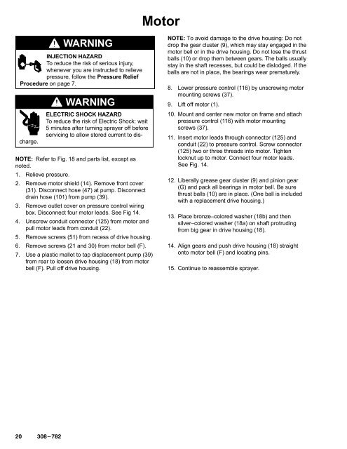
Motor<br />
WARNING<br />
INJECTION HAZARD<br />
To reduce the risk of serious injury,<br />
whenever you are instructed to relieve<br />
pressure, follow the Pressure Relief<br />
Procedure on page 7.<br />
ELECTRIC SHOCK HAZARD<br />
To reduce the risk of Electric Shock: wait<br />
5 minutes after turning sprayer off before<br />
servicing to allow stored current to discharge.<br />
WARNING<br />
NOTE: Refer to Fig. 18 and parts list, except as<br />
noted.<br />
1. Relieve pressure.<br />
2. Remove motor shield (14). Remove front cover<br />
(31). Disconnect hose (47) at pump. Disconnect<br />
drain hose (101) from pump (39).<br />
3. Remove outlet cover on pressure control wiring<br />
box. Disconnect four motor leads. See Fig 14.<br />
4. Unscrew conduit connector (125) from motor and<br />
pull motor leads from conduit (22).<br />
5. Remove screws (51) from recess of drive housing.<br />
6. Remove screws (21 and 30) from motor bell (F).<br />
7. Use a plastic mallet to tap displacement pump (39)<br />
from rear to loosen drive housing (18) from motor<br />
bell (F). Pull off drive housing.<br />
NOTE: To avoid damage to the drive housing: Do not<br />
drop the gear cluster (9), which may stay engaged in the<br />
motor bell or in the drive housing. Do not lose the thrust<br />
balls (10) or drop them between gears. The balls usually<br />
stay in the shaft recesses, but could be dislodged. If the<br />
balls are not in place, the bearings wear prematurely.<br />
8. Lower pressure control (116) by unscrewing motor<br />
mounting screws (37).<br />
9. Lift off motor (1).<br />
10. Mount and center new motor on frame and attach<br />
pressure control (116) with motor mounting<br />
screws (37).<br />
11. Insert motor leads through connector (125) and<br />
conduit (22) to pressure control. Screw connector<br />
(125) two or three threads into motor. Tighten<br />
locknut up to motor. Connect four motor leads.<br />
See Fig. 14.<br />
12. Liberally grease gear cluster (9) and pinion gear<br />
(G) and pack all bearings in motor bell. Be sure<br />
thrust balls (10) are in place. (One ball is included<br />
with a replacement drive housing.)<br />
13. Place bronze–colored washer (18b) and then<br />
silver–colored washer (18a) on shaft protruding<br />
from big gear in drive housing (18).<br />
14. Align gears and push drive housing (18) straight<br />
onto motor bell (F) and locating pins.<br />
15. Continue to reassemble sprayer.


