R8C/13 Group APPLICATION NOTE Flash Rewrite Using EW1 Mode
R8C/13 Group APPLICATION NOTE Flash Rewrite Using EW1 Mode
R8C/13 Group APPLICATION NOTE Flash Rewrite Using EW1 Mode

Create successful ePaper yourself
Turn your PDF publications into a flip-book with our unique Google optimized e-Paper software.
<strong>R8C</strong>/<strong>13</strong> <strong>Group</strong><br />
<strong>Flash</strong> <strong>Rewrite</strong> <strong>Using</strong> <strong>EW1</strong> <strong>Mode</strong> (Data "FFh" Search)<br />
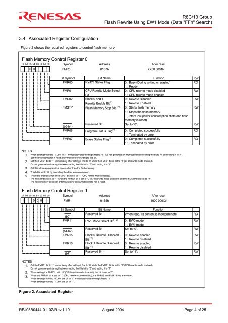
3.4 Associated Register Configuration<br />
Figure 2 shows the required registers to control flash memory<br />
<strong>Flash</strong> Memory Control Register 0<br />
b7 b6 b5 b4 b3 b2 b1 b0<br />
<strong>NOTE</strong>S :<br />
1.<br />
2.<br />
3.<br />
4.<br />
5.<br />
<strong>Flash</strong> Memory Control Register 1<br />
1 0<br />
<strong>NOTE</strong>S :<br />
1.<br />
2.<br />
3.<br />
0 0<br />
Symbol Address After reset<br />
FMR0 01B7h XX00 0001b<br />
Bit Symbol<br />
Bit Name<br />
Function<br />
RW<br />
FMR00 RY/BY Status Flag 0 : Busy (During writing or erasing) RO<br />
1 : Ready<br />
FMR01 CPU <strong>Rewrite</strong> <strong>Mode</strong> Select 0 : CPU rewrite mode disabled RW<br />
Bit (1)<br />
1 : CPU rewrite mode enabled<br />
FMR02 Block 0 and 1<br />
0 : <strong>Rewrite</strong> Disabled RW<br />
<strong>Rewrite</strong> Enable Bit (2) 1 : <strong>Rewrite</strong> Enabled<br />
FMSTP <strong>Flash</strong> Memory Stop Bit (3,5) 0 : Starts flash memory RW<br />
1 : Stops the flash memory<br />
(Enters low-power consumption state and flash<br />
memory is reset)<br />
(b5-b4)<br />
Reserved Bit<br />
Set to “0”.<br />
RW<br />
FMR06 Program Status Flag (4) 0 : Completed successfully RO<br />
1 : Teminated by error<br />
FMR07 Erase Status Flag (4) 0 : Completed successfully RO<br />
1 : Teminated by error<br />
When setting this bit to “1”, set to “1” immediately after setting it first to “0”. Do not generate an interrupt between setting the bit to “0” and setting it to “1”.<br />
Set the microcomputer in read array mode before writing to this bit.<br />
Set the FMR01 bit to “1” immediately after setting it first to “0” while the FMR01 bit is set to “1” (CPU rewrite mode enabled).<br />
Do not generate an interrupt between setting the this bit to “0” and setting it to “1”.<br />
Set this bit by a program in a space other than the flash memory.<br />
This bit is set to “0” by executing the clear status command.<br />
This bit is enabled when the FMR01 bit is set to “1” (CPU rewrite mode enabled).<br />
The FMSTP bit is set to “1” when the FMR01 bit is set to “0” (CPU rewrite mode disabled) and the FMSTP bit is set to “1”.<br />
The flash memory does not enter low-power consumption state nor is reset.<br />
b7 b6 b5 b4 b3 b2 b1 b0<br />
0 0<br />
Symbol Address After reset<br />
FMR1 01B5h 1000 000Xb<br />
Bit Symbol<br />
Bit Name<br />
Function<br />
(b0)<br />
Reserved Bit<br />
When read, its content is indeterminate.<br />
RO<br />
FMR11 <strong>EW1</strong> <strong>Mode</strong> Select Bit (1,2) 0 : EW0 mode RW<br />
(b4-b2)<br />
Reserved Bit<br />
1 : <strong>EW1</strong> mode<br />
Set to “0”.<br />
RW<br />
FMR15 Block 0 <strong>Rewrite</strong> Disabled 0 : <strong>Rewrite</strong> enabled RW<br />
Bit (2,3)<br />
1 : <strong>Rewrite</strong> disabled<br />
FMR16 Block 1 <strong>Rewrite</strong> Disabled 0 : <strong>Rewrite</strong> enabled RW<br />
(b7)<br />
Bit (2,3)<br />
Reserved Bit<br />
1 : <strong>Rewrite</strong> disabled<br />
Set to “1”.<br />
RW<br />
Set the FMR01 bit to “1” immediately after setting it first to “0” while the FMR01 bit is set to “1” (CPU rewrite mode enabled).<br />
Do not generate an interrupt between setting the this bit to “0” and setting it to “1”.<br />
When setting the FMR01 bit to “0” (CPU rewrite mode disabled), this bit is set to “0”.<br />
When the FMR01 bit is set to “1” (CPU rewrite mode enabled), the FMR15 and FMR16 bits are written.<br />
When setting this bit to “0”, set this bit to “0” immediately after setting it first to “1”.<br />
When setting this bit to “1”, set this bit to “1”.<br />
Figure 2. Associated Register<br />
REJ05B0444-0110Z/Rev.1.10 August 2004 Page 4 of 25