MAN-C3E-0004 - Güralp Systems Limited
MAN-C3E-0004 - Güralp Systems Limited
MAN-C3E-0004 - Güralp Systems Limited

Create successful ePaper yourself
Turn your PDF publications into a flip-book with our unique Google optimized e-Paper software.
CMG-3EX-EAM<br />
Digital Broadband Seismometer<br />
Operator's Guide<br />
Part No. <strong>MAN</strong>-<strong>C3E</strong>-<strong>0004</strong><br />
Designed and manufactured by<br />
<strong>Güralp</strong> <strong>Systems</strong> <strong>Limited</strong><br />
3 Midas House, Calleva Park<br />
Aldermaston RG7 8EA<br />
England<br />
Proprietary Notice: The information in this manual is<br />
proprietary to <strong>Güralp</strong> <strong>Systems</strong> <strong>Limited</strong> and may not be<br />
copied or distributed outside the approved recipient's<br />
organisation without the approval of <strong>Güralp</strong> <strong>Systems</strong><br />
<strong>Limited</strong>. <strong>Güralp</strong> <strong>Systems</strong> <strong>Limited</strong> shall not be liable for<br />
technical or editorial errors or omissions made herein,<br />
nor for incidental or consequential damages resulting<br />
from the furnishing, performance, or usage of this<br />
material.<br />
Issue A 2010-05-18
CMG-3EX-EAM Digital Broadband Seismometer<br />
Table of Contents<br />
1 Introduction..............................................................................................................3<br />
2 Internal Modules......................................................................................................4<br />
3 External Connectors and Controls..........................................................................5<br />
3.1 Mass Control......................................................................................................6<br />
3.1.1 Unlock........................................................................................................7<br />
3.1.2 Centre..........................................................................................................7<br />
3.1.3 Lock.............................................................................................................7<br />
3.1.4 Auto Lock....................................................................................................7<br />
3.1.5 Auto Centre.................................................................................................8<br />
3.2 Busy LEDs..........................................................................................................8<br />
4 Data flush control...................................................................................................10<br />
5 USB Operations......................................................................................................11<br />
5.1 USB device mode.............................................................................................11<br />
5.2 USB host mode................................................................................................11<br />
6 What to read next...................................................................................................12<br />
7 Revision history......................................................................................................13<br />
2 Issue A
1 Introduction<br />
Operator's Guide<br />
The CMG-3ESPCD is a full-featured three-axis digital seismometer<br />
consisting of three sensors in a lightweight case, which can measure<br />
the North/South, East/West and vertical components of ground motion<br />
simultaneously, a built-in CMG-CD24 digitizer and a built-in CMG-<br />
EAM embedded acquisition module.<br />
Each sensor is sensitive to ground vibrations in the frequency range<br />
120 seconds to 50 Hz, a broadband frequency response made possible<br />
by advanced force-balance feedback electronics. Because of this wide<br />
response range, the 3ESPCD can replace many of the instruments<br />
conventionally used in a seismic observatory; it also produces true<br />
pulse-shape records suitable for modern earthquake mechanism<br />
analysis. Its small size and low weight make it an ideal choice for<br />
rapid deployment of low-noise installations.<br />
The seismometer unit is selfcontained<br />
apart from its 12 V power<br />
supply. Once levelled and centred,<br />
it will begin operating<br />
automatically. Its output is<br />
digitized within the sensor by the<br />
internal CD24 digitizer, which<br />
provides data streams to the<br />
embedded acquisition module. The<br />
instrument can be connected to a<br />
PC over a serial port or Ethernet<br />
network. The text- or web-based<br />
configuration interface provides<br />
complete control over the storage<br />
and transmission of data, as well as<br />
the instrument's centring and mass<br />
locking processes. Data stored in<br />
the internal memory can be written<br />
to an external USB drive at the<br />
touch of a button.<br />
Each seismometer is delivered with a detailed calibration sheet<br />
showing its serial number, measured frequency response in both the<br />
long period and the short period sections of the seismic spectrum,<br />
sensor DC calibration levels, and the transfer function in poles/zeros<br />
notation.<br />
May 2010 3
CMG-3EX-EAM Digital Broadband Seismometer<br />
2 Internal Modules<br />
The CMG-3EX-EAM is composed of three internal modules:<br />
• The triaxial sensor assembly;<br />
• The analogue-to-digital converter (digitiser); and<br />
• The embedded acquisition module.<br />
Each of these modules is described in detail in a separate manual. The<br />
sensor itself is described in <strong>MAN</strong>-<strong>C3E</strong>-0001, the analogue-to-digital<br />
converter module is described in <strong>MAN</strong>-C24-0001 and the embedded<br />
acquisition module is described in <strong>MAN</strong>-EAM-0001. If you wish to<br />
transmit data in CD1.1 format, you will also need <strong>MAN</strong>-EAM-1100.<br />
Many common tasks can be performed in more than one way. For<br />
example, mass locking and unlocking can be initiated from the<br />
digitiser's command line, from the web interface of the embedded<br />
acquisition module, using a copy of Scream! software or by using the<br />
push-button controls on the top of the instrument.<br />
This document provides additional information specific to the CMG-<br />
3EX-EAM and refers the reader, where necessary, to the manuals<br />
mentioned above for operational details which are not peculiar to this<br />
instrument.<br />
4 Issue A
3 External Connectors and Controls.<br />
Operator's Guide<br />
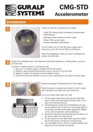
On the top of the instrument, you will find:<br />
• An Ethernet connector, labelled NET;<br />
• A general purpose input/output connector, labelled GPIO;<br />
• A universal serial bus connector, labelled USB;<br />
• The handle, with an arrow indicating “North”;<br />
• A bubble-level;<br />
• A “breather” screw, to allow the instrument to be assembled<br />
without a build-up of pressure internally.<br />
May 2010 5
CMG-3EX-EAM Digital Broadband Seismometer<br />
• A power and data connector, labelled DATA;<br />
• A GPS receiver connector, labelled GPS;<br />
• Five coloured push-buttons (described below);<br />
• A red LED (next to the yellow push-button) to indicate when<br />
data is being flushed to storage (described below); and<br />
• Two LEDs, one red, one green, next to the black push-button,<br />
to indicate the progress of locking, unlocking and centring<br />
operations.<br />
The five connectors, NET, GPIO, USB, DATA and GPS, are connected<br />
internally to the embedded acquisition module and are described in<br />
<strong>MAN</strong>-EAM-0001.<br />
The use of the “North” indication and the bubble level are described in<br />
<strong>MAN</strong>-<strong>C3E</strong>-0001.<br />
The use of the push-buttons and LEDs are described in the following<br />
section.<br />
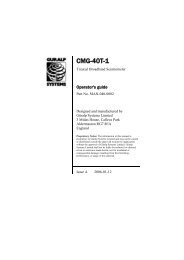
3.1 Mass Control<br />
The sensors' masses can be locked, unlocked and centred using the<br />
digitiser's command line, the embedded acquisition module's text or<br />
web interface, Scream! software or the push-buttons on the top of the<br />
instrument. This section describes how to use the push buttons.<br />
6 Issue A
Operator's Guide<br />
The two LED's, on the right in the illustration above, provide an<br />
indication of the instruments status.<br />
3.1.1 Unlock<br />
To initiate the unlock function hold down the green unlock button,<br />
then press the black enable button and release both after<br />
approximately 10 seconds. The internal processor will now perform<br />
the task of unlocking the sensor. There are several stages to this and<br />
the green LED shows the progress. If an error is encountered during<br />
the unlock process, the red LED will flash at the end of the operation.<br />
The precise pattern of flashing indicates the fault encountered. Details<br />
of LED states can be found in section 3.2 on page 8.<br />
3.1.2 Centre<br />
To initiate the centre function hold down the blue centre button, then<br />
press the black enable button and release both after approximately 10<br />
seconds. The internal processor will now perform the task of centring<br />
the sensor. The green LED flashes during the centre process and then<br />
stays on once the centre is successful. If an error is encountered during<br />
the centring process, the red LED will illuminate at the end of the<br />
operation. The precise pattern of flashing indicates the fault<br />
encountered. Details of LED states can be found in section 3.2 on page<br />
8.<br />
3.1.3 Lock<br />
To initiate the lock function hold down the red lock button, then press<br />
the black enable button and release both after approximately 10<br />
seconds. The internal processor will now perform the task of locking<br />
the sensor. There are several stages to this and the green LED shows<br />
the progress. If an error is encountered during the locking process, the<br />
red LED will illuminate at the end of the operation. The precise<br />
pattern of flashing indicates the fault encountered. Details of LED<br />
states can be found in section 3.2 on page 8.<br />
3.1.4 Auto Lock<br />
The sensor has an automatic lock feature to ensure that the sensor is<br />
always locked when transported. If power is removed from the sensor<br />
for more than thirty seconds, an internal NiMH battery provides<br />
enough energy to initiate an automatic locking sequence.<br />
Note: If the sensor has been left standing powered off for expended<br />
periods of time (>3months) the sensor should be left powered for at<br />
least 48 hours before deployment to ensure that the internal battery is<br />
May 2010 7
CMG-3EX-EAM Digital Broadband Seismometer<br />
charged. Failure to do this may result in the auto lock function failing<br />
and damage to the sensor.<br />
The auto-lock feature is enabled at the factory but can be disabled if<br />
desired.<br />
To disable or re-enable the auto lock function hold down both the blue<br />
centre and green unlock button, then press the black enable button<br />
until the red LED illuminates continuously. This sequence toggles the<br />
sensor between auto-lock enabled and disabled. Both busy LEDs blink<br />
together continuously to indicated the sensors' mode. The sensor<br />
should not be in a fault state prior to enabling this function. Details of<br />
LED states can be found in section 3.2 on page 8.<br />
3.1.5 Auto Centre<br />
The instrument has an automatic centre function that will centre the<br />
sensor massse if their position exceeds a set threshold.<br />
To enable and disable the auto centre function hold down both the<br />
blue centre and the red lock buttons, then press the black enable<br />
button until the red LED illuminates continuously. This sequence<br />
toggles the sensor between auto-centre enabled and disabled. Both<br />
busy LED's blink together continuously to indicated the sensors' mode.<br />
The sensor should not be in a fault state prior to enabling this<br />
function. Details of LED states can be found in section 3.2 on page 8.<br />
When Auto centre is enabled the sensor will initiate a centre operation<br />
if the mass position of any component exceeds the threshold<br />
continuously, for a set Delay period.<br />
The default threshold is set to +/-1000 counts which is +/-50% full<br />
scale. The delay period is set to 10 which equates to around 10<br />
minutes.<br />
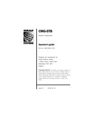
3.2 Busy LEDs<br />
The busy LEDs show the various states of the instrument. To do this<br />
they illuminate and flash in different sequences. The status LED<br />
sequence is based on 8 time segments that are repeated Either LED<br />
can be on or off during each time segment. The table below explains<br />
the LED states. A series of symbols are used to show when the LED is<br />
on or off.<br />
Here the symbol will indicate the led is off during a time segment<br />
and the symbol or will indicate that the red or green LED is on.<br />
8 Issue A
Operator's Guide<br />
So the sequence of symbols indicates the the green<br />
LED is off for a long period of time (5 segments) then flashes twice.<br />
LED sequence<br />
Red: <br />
Green: <br />
Red: <br />
Green: <br />
Red: <br />
Green: <br />
Red: <br />
Green: <br />
Red: <br />
Green: <br />
Red: <br />
Green: <br />
Red: <br />
Green: <br />
Red: <br />
Green: <br />
Red: <br />
Green: <br />
Red: <br />
Green: <br />
Red: <br />
Green: <br />
Red: <br />
Green: <br />
Red: <br />
Green: <br />
Red: <br />
Green: <br />
Red: <br />
Green: <br />
Red: <br />
Green: <br />
Description of status<br />
Sensor is locked or powered off and no<br />
automatic functions are selected.<br />
Only auto-centre is enabled.<br />
Only auto-lock is enabled.<br />
Both auto-lock and auto-centre are enabled.<br />
Sensor is centred: auto-lock and auto-centre<br />
are both disabled.<br />
Sensor is centred and only auto-centre is<br />
enabled.<br />
Sensor is centred and only auto-lock is<br />
enabled.<br />
Sensor is centred and both auto-lock and<br />
auto-centre are enabled.<br />
Sensor is locking.<br />
Sensor is unlocking<br />
Sensor is centring<br />
Power failure waiting for auto-lock delay to<br />
time out (alternating red/green flashes).<br />
Catastrophic failure the sensor has a fault<br />
that has made it impossible to complete the<br />
last operation.<br />
Locking system limit switch fault.<br />
Horizontal tilt base limit. This could be a<br />
result of a poorly levelled sensor.<br />
The current operation timed out. This could<br />
indicate a fault or, in the case of centring, the<br />
sensor may need to be re-centred.<br />
May 2010 9
CMG-3EX-EAM Digital Broadband Seismometer<br />
4 Data flush control<br />
The CMG-3EX-EAM has an internal ring-buffer for storing seismic<br />
data. If an external storage device is connected and configured for<br />
data storage, the CMG-3EX-EAM will leave it powered down for most<br />
of the time, in order to conserve energy. Periodically, the CMG-3EX-<br />
EAM will power up the external storage device and flush the data from<br />
the ring buffer to it. (To configure an external storage device for use in<br />
this way, see Section 10.2 of <strong>MAN</strong>-EAM-0001.)<br />
When data need to be retrieved, e.g. at a site visit or at the end of a<br />
deployment, a manual flush to stoarge should be initiaited in order to<br />
ensure that the most recent data are written to the external device.<br />
This process can be initiated using the yellow “flush” button on the<br />
instrument's lid<br />
To start a flush, hold down the yellow flush button then press the<br />
black enable button for approximately 10 seconds. The flush LED<br />
should now illuminate to indicate that the transfer is in progress.<br />
If the LED remains illuminated for only a few seconds, the flush has<br />
failed; the EAM module will retry after 60 seconds (and will retry up to<br />
three times before aborting).<br />
When the flush is complete, the LED will extinguish. It is now safe to<br />
remove the external storage device.<br />
Flushing data using the lid controls it identical to the web 'flush'<br />
command and transfers from flash to external storage all data that have<br />
been recorded since the last transfer was carried out.<br />
10 Issue A
5 USB Operations<br />
Operator's Guide<br />
The CMG-3EX-EAM can function as both a storage device, available<br />
for access from a USB connected PC, and as a USB host, writing to<br />
external USB storage devices such as memory sticks and USB disks.<br />
When used as a USB storage device, the GPIO connector is employed.<br />
When acting as a host, the USB connector is used. The pin-outs of<br />
both these connectors are given in the appendices of <strong>MAN</strong>-EAM-0001.<br />
5.1 USB device mode<br />
The CMG-3EX-EAM is fitted with an internal Flash memory device<br />
which is accessible via USB. It can be written to by selecting “Internal<br />
USB storage” from the “Recording destination” drop-down menu on<br />
the “Disk recording” menu (see section 10.2 of <strong>MAN</strong>-EAM-0001).<br />
When a USB host, such as a laptop or PC, is connected to the GPIO<br />
port internal circuitry detects the USB power and automatically<br />
connects the Flash memory to the USB socket, causing it to behave<br />
identically to a standard USB memory stick.<br />
When no power is detected at the USB port, the Flash memory is<br />
available to the system as if it were a standard removable disk. All of<br />
the disk recording options described in section 10.2 of <strong>MAN</strong>-EAM-<br />
0001 will apply to this device.<br />
5.2 USB host mode<br />
If a USB storage device is connected to the USB port, it will be<br />
mounted under /media. It can be used to store seismic data by<br />
selecting “External USB drive on mil-spec connector” from the<br />
“Recording destination” drop-down menu on the “Disk recording”<br />
menu, described in section 10.2 of <strong>MAN</strong>-EAM-0001.<br />
May 2010 11
CMG-3EX-EAM Digital Broadband Seismometer<br />
6 What to read next...<br />
• To connect to your instrument over a serial or Ethernet link, see<br />
Sections 2 and 6 of <strong>MAN</strong>-EAM-0001.<br />
• To prepare a site and install your instrument, see Section 2 of <strong>MAN</strong>-<br />
<strong>C3E</strong>-0001.<br />
• To calibrate your instrument, see Section 3 of <strong>MAN</strong>-<strong>C3E</strong>-0001.<br />
• To configure sample rates and triggering, see Section 7 of <strong>MAN</strong>-<br />
EAM-0001.<br />
• To record and retrieve data, see Section 10 of <strong>MAN</strong>-EAM-0001.<br />
• For connector pin-out details, see Section 14.3 of <strong>MAN</strong>-EAM-0001.<br />
12 Issue A
Operator's Guide<br />
7 Revision history<br />
2010-03-26 A New document<br />
May 2010 13