Download
Download
Download

Create successful ePaper yourself
Turn your PDF publications into a flip-book with our unique Google optimized e-Paper software.
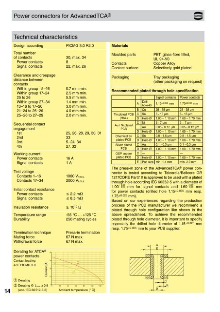
Power connectors for AdvancedTCA ®<br />
Technical characteristics<br />
Design according PICMG 3.0 R2.0<br />
Total number<br />
of contacts 30, max. 34<br />
Power contacts 8<br />
Signal contacts 22, max. 26<br />
Clearance and creepage<br />
distance between<br />
contacts<br />
Within group 5–16 0.7 mm min.<br />
Within group 17–24 2.5 mm min.<br />
25 to 26 5.5 mm min.<br />
Within group 27–34 1.4 mm min.<br />
13–16 to 17–20 3.0 mm min.<br />
21–24 to 25–26 4.0 mm min.<br />
25–26 to 27–29 2.0 mm min.<br />
Sequential contact<br />
engagement<br />
1st 25, 26, 28, 29, 30, 31<br />
2nd 33<br />
3rd 5–24, 34<br />
4th 27, 32<br />
Working current<br />
Power contacts<br />
Signal contacts<br />
Test voltage<br />
Contacts 1–16<br />
Contacts 17–34<br />
Initial contact resistance<br />
Power contacts<br />
Signal contacts<br />
Insulation resistance<br />
16 A<br />
1 A<br />
1000 V r.m.s.<br />
2000 V r.m.s.<br />
£ 2.2 mW<br />
£ 8.5 mW<br />
³ 10 10 W<br />
Temperature range -55 °C … +125 °C<br />
Durability<br />
250 mating cycles<br />
Termination technique<br />
Mating force<br />
Withdrawal force<br />
Press-in termination<br />
67 N max.<br />
67 N max.<br />
Materials<br />
Moulded parts<br />
Contacts<br />
Contact surface<br />
Packaging<br />
PBT, glass-fibre filled,<br />
UL 94-V0<br />
Copper Alloy<br />
Selectively gold plated<br />
Tray packaging<br />
(other packaging on request)<br />
Recommended plated through hole specification<br />
Tin plated PCB<br />
(HAL)<br />
Au / Ni plated<br />
PCB<br />
Chemical tin<br />
plated PCB<br />
Silver plated<br />
PCB<br />
OSP copper<br />
plated PCB<br />
Signal contacts Power contacts<br />
A<br />
Drill<br />
hole-Ø 1.15±0.025 mm 1.75 ±0.025 mm<br />
B Cu 25 - 35 µm 25 - 35 µm<br />
C Sn 5 - 15 µm 5 - 15 µm<br />
D Hole-Ø 1.00 – 1.10 mm 1.60 – 1.70 mm<br />
C Ni 3 - 7 µm 3 – 7 µm<br />
Au 0.05 - 0.12 µm 0.05 - 0.12 µm<br />
D Hole-Ø 1.00 – 1.10 mm 1.60 – 1.70 mm<br />
C Sn 0.8 - 1.5 µm 0.8 - 1.5 µm<br />
D Hole-Ø 1.00 – 1.10 mm 1.60 – 1.70 mm<br />
C Ag 0.1 - 0.3 µm 0.1 - 0.3 µm<br />
D Hole-Ø 1.00 – 1.10 mm 1.60 – 1.70 mm<br />
C --- --- ---<br />
D Hole-Ø 1.00 – 1.10 mm 1.60 – 1.70 mm<br />
E Pad size min. 1.4 mm min. 2.0 mm<br />
The press-in zone of the AdvancedTCA ® power connector<br />
is tested according to Telcordia/Bellcore GR<br />
1217CORE Part7. It is approved to be used with a plated<br />
through hole according IEC 60352-5 with a diameter of<br />
1.00 + 0.09<br />
– 0.06 mm for signal contacts and 1.60 + 0.09<br />
– 0.06 mm<br />
for power contacts (drilled hole 1.15 ±0.025 mm resp.<br />
1.75 ±0.025 mm).<br />
Based on our experiences regarding the production<br />
process of the PCB manufacturer we recommend a<br />
plated through hole configuration like shown in the<br />
above spreadsheet. To achieve the recommended<br />
plated through hole diameter, it is important to specify<br />
especially the drilled hole diameter of 1.15 ±0.025 mm<br />
resp. 1.75 ±0.025 mm to your PCB supplier.<br />
14<br />
Derating for ATCA ®<br />
power contacts<br />
Contact loading<br />
acc. PICMG 3.0<br />
Current [A]<br />
À Derating<br />
Á Derating @ I max. x 0.8<br />
(acc. IEC 60 512-5-2) Ambient temperature [° C]