Download
Download
Download

Create successful ePaper yourself
Turn your PDF publications into a flip-book with our unique Google optimized e-Paper software.
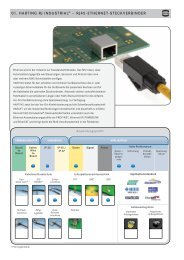
General information about Plug Connectors<br />
The PICMG specification AMC.0 defined a card<br />
edge with gold pads as the mating interface for the<br />
AdvancedMC module.<br />
As already explained in<br />
the chapter “con:card+”,<br />
it is very difficult for a PCB<br />
manufacturer to produce<br />
the tight tolerances required<br />
for the AdvancedMC<br />
module card edge in<br />
a consistent process.<br />
Furthermore, the quality<br />
of the gold pads is only<br />
specified in general terms.<br />
Replacing the PCB gold pads with a connector<br />
eliminates certain drawbacks of the card edge<br />
connection. The HARTING Plug Connector offers the<br />
following advantages:<br />
• Controlled quality of both mating sides<br />
• Small dimensional tolerances<br />
• Defined hard gold surface<br />
• Reduced mating forces<br />
• Allows use of thicker PCBs<br />
• Standard reflow solder process<br />
• Cost savings are possible<br />
the moulding process has a dimensional tolerance<br />
less than 0.03 mm. The lead-in chamfer is milled for<br />
the PCB but is realized in the connector as a smooth<br />
moulded plastic chamfer. Compared with the rough<br />
surface of a PCB chamfer with exposed glass fibre, the<br />
smooth Plug chamfer avoids abrasion of the backplane<br />
connector contact surface.<br />
Defined hard gold surface<br />
The AMC.0 specification defines hard gold to be on the<br />
PCB pads. However a common and unique definition<br />
of hard gold does not exist today. Additionally, the<br />
interruptions of the gold pads (which are necessary<br />
for the hot-swap ability) require a selective hard gold<br />
process. This is a complex process which is relatively<br />
expensive, so commonly just chemical gold with<br />
insufficient surface thickness is used. As a result, there<br />
are significant differences in the durability of the gold<br />
and the surface structure on the modules which are<br />
currently available.<br />
The contacts of the HARTING AdvancedMC Plug<br />
Connector are plated all-around and are manufactured<br />
in a defined band plating process with controlled<br />
quality. There are different performance levels possible<br />
as the noble finish thickness can be adapted easily to<br />
meet customer demands.<br />
Reduced mating forces<br />
For the module card edge, the prepads of lagging<br />
contacts are required by the Telcordia/Bellcore<br />
specification to avoid stress of the connector contact<br />
when sliding on the FR4 base material. The Plug<br />
Connector does not need prepads. The four mating<br />
steps are realized with true lagging contacts. The<br />
sophisticated design of the insulator reduces the<br />
mating forces of the module significantly.<br />
Controlled quality of both mating sides<br />
The major advantage is that a solid contact with<br />
a band plated surface mates with the backplane<br />
connector. The connection is no longer made directly<br />
from the card edge to the backplane connector but<br />
instead indirectly via a module connector approved<br />
from one source. The AdvancedMC module with a<br />
Plug Connector is still within the dimensional range<br />
of the PICMG AMC.0 specification and is fully mating<br />
compatible with AdvancedMC card edge connectors.<br />
Consequently the Plug Connector can be used in both<br />
MicroTCA and ATCA ® environments.<br />
Small dimensional tolerances<br />
The injection moulding process is much more precise<br />
than the PCB production process. While the AMC.0<br />
specification defines a PCB width tolerance of 0.1 mm,<br />
Allows use of thicker PCBs<br />
By using a HARTING AdvancedMC Plug Connector,<br />
the mating interface of the module is defined by the<br />
connector instead of the PCB. This fact leads to clear<br />
advantages and provides a wider scope for the module<br />
development. The restriction of the PCB thickness of<br />
1.6 mm +/-10% is no longer a limiting factor. A PCB<br />
21