Download
Download
Download

Create successful ePaper yourself
Turn your PDF publications into a flip-book with our unique Google optimized e-Paper software.
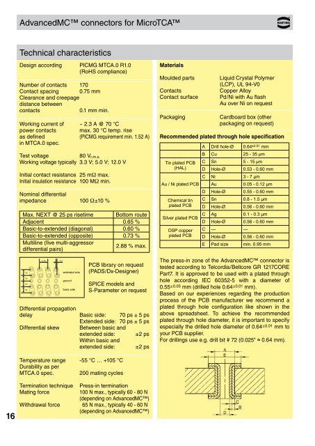
AdvancedMC connectors for MicroTCA<br />
Technical characteristics<br />
Design according PICMG MTCA.0 R1.0<br />
(RoHS compliance)<br />
Number of contacts 170<br />
Contact spacing 0.75 mm<br />
Clearance and creepage<br />
distance between<br />
contacts<br />
0.1 mm min.<br />
Working current of ~ 2.3 A @ 70 °C<br />
power contacts max. 30 °C temp. rise<br />
as defined (PICMG requirement min. 1.52 A)<br />
in MTCA.0 spec.<br />
Test voltage<br />
80 V r.m.s.<br />
Working voltage typically 3.3 V; 5.0 V; 12.0 V<br />
Initial contact resistance 25 mW max.<br />
Initial insulation resistance 100 MW min.<br />
Nominal differential<br />
impedance 100 W±10 %<br />
Max. NEXT @ 25 ps risetime Bottom route<br />
Adjacent 0.65 %<br />
Basic-to-extended (diagonal) 0.60 %<br />
Basic-to-extended (opposite) 0.73 %<br />
Multiline (five multi-aggressor<br />
differential pairs)<br />
2.88 % max.<br />
1.5<br />
1.5<br />
1.5<br />
1.5<br />
2.25 0.2<br />
extended side<br />
ground<br />
basic side<br />
Crosstalk_MicroTCA.indd 1 04.02.2008 13:23:08<br />
PCB library on request<br />
(PADS/Dx-Designer)<br />
SPICE models and<br />
S-Parameter on request<br />
Differential propagation<br />
delay Basic side: 70 ps ± 5 ps<br />
Extended side: 70 ps ± 5 ps<br />
Differential skew Between basic and<br />
extended side: ±2 ps<br />
Within basic and<br />
extended side: ±2 ps<br />
Materials<br />
Moulded parts<br />
Contacts<br />
Contact surface<br />
Packaging<br />
Liquid Crystal Polymer<br />
(LCP), UL 94-V0<br />
Copper Alloy<br />
Pd/Ni with Au flash<br />
Au over Ni on request<br />
Cardboard box (other<br />
packaging on request)<br />
Recommended plated through hole specification<br />
Tin plated PCB<br />
(HAL)<br />
Au / Ni plated PCB<br />
Chemical tin<br />
plated PCB<br />
Silver plated PCB<br />
OSP copper<br />
plated PCB<br />
A Drill hole-Ø 0.64 ±0.01 mm<br />
B Cu 25 - 35 µm<br />
C Sn 5 - 15 µm<br />
D Hole-Ø 0.53 - 0.60 mm<br />
C Ni 3 - 7 µm<br />
Au 0.05 - 0.12 µm<br />
D Hole-Ø 0.55 - 0.60 mm<br />
C Sn 0.8 - 1.5 µm<br />
D Hole-Ø 0.56 - 0.60 mm<br />
C Ag 0.1 - 0.3 µm<br />
D Hole-Ø 0.56 - 0.60 mm<br />
C --- ---<br />
D Hole-Ø 0.56 - 0.60 mm<br />
E Pad size min. 0.95 mm<br />
The press-in zone of the AdvancedMC connector is<br />
tested according to Telcordia/Bellcore GR 1217CORE<br />
Part7. It is approved to be used with a plated through<br />
hole according IEC 60352-5 with a diameter of<br />
0.55 ±0.05 mm (drilled hole 0.64 ±0.01 mm).<br />
Based on our experiences regarding the production<br />
process of the PCB manufacturer we recommend a<br />
plated through hole configuration like shown in the<br />
above spreadsheet. To achieve the recommended<br />
plated through hole diameter, it is important to specify<br />
especially the drilled hole diameter of 0.64 ±0.01 mm to<br />
your PCB supplier.<br />
For drillings use e.g. drill bit # 72 (0.025" ≈ 0.64 mm).<br />
Temperature range -55 °C … +105 °C<br />
Durability as per<br />
MTCA.0 spec. 200 mating cycles<br />
16<br />
Termination technique<br />
Mating force<br />
Withdrawal force<br />
Press-in termination<br />
100 N max., typically 60 - 80 N<br />
( depending on AdvancedMC)<br />
65 N max., typically 40 - 60 N<br />
( depending on AdvancedMC)