Download
Download
Download

You also want an ePaper? Increase the reach of your titles
YUMPU automatically turns print PDFs into web optimized ePapers that Google loves.
General information about Plug Connectors<br />
thickness of e.g. 2 mm can be used as this fits in the<br />
mechanical environment.<br />
Standard reflow solder process<br />
For backplanes press-fit termination is the first choice,<br />
however solder termination offers advantages for<br />
module cards. The Plug Connector is mounted to the<br />
PCB through “pin-inhole-reflow”<br />
solder<br />
technology (PIHR).<br />
It can be soldered in<br />
the same production<br />
process as the<br />
other semi finished<br />
components on the<br />
AdvancedMC<br />
module. Optionally,<br />
the Plug Connector<br />
can be delivered with a pick-and-place-pad for<br />
automatic assembly.<br />
Another advantage of this mechanically stable<br />
technology is, that the connector can be replaced. This<br />
can avoid the cost of scrapping a module if the mating<br />
interface is damaged during handling.<br />
Cost savings are possible<br />
By offering so many different advantages during the<br />
manufacturing process, the use of HARTING Plug<br />
Connectors also contributes to keeping costs down.<br />
Selective plating increases the cost of producing gold<br />
pads. Tight tolerance specifications also cause a large<br />
number of rejects. The beveled PCB edge is another<br />
critical area, because damage can occur to the contact<br />
pads.<br />
A simple board layout with through-holes is sufficient<br />
for the HARTING Plug, and these boards can be<br />
produced inexpensively and with excellent quality<br />
control, thus reducing the number of rejects.<br />
Furthermore the cost of a reject can be high if a<br />
defective PCB edge is not detected until the board is<br />
populated with expensive components. A HARTING<br />
Plug on a module can be replaced easily, reducing<br />
scrapping costs.<br />
Mounting direction<br />
The HARTING Plug Connector is available in two<br />
versions. The difference is the mounting direction, i. e.<br />
the side of the AdvancedMC module PCB on which<br />
the Plug Connector is assembled.<br />
22<br />
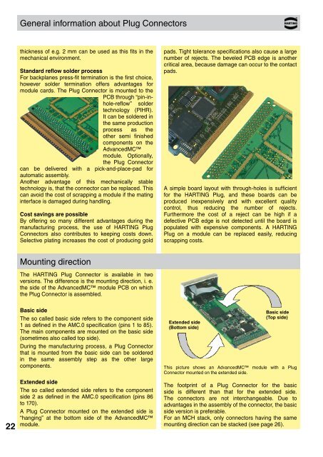
Basic side<br />
The so called basic side refers to the component side<br />
1 as defined in the AMC.0 specification (pins 1 to 85).<br />
The main components are mounted on the basic side<br />
(sometimes also called top side).<br />
During the manufacturing process, a Plug Connector<br />
that is mounted from the basic side can be soldered<br />
in the same assembly step as the other large<br />
components.<br />
Extended side<br />
The so called extended side refers to the component<br />
side 2 as defined in the AMC.0 specification (pins 86<br />
to 170).<br />
A Plug Connector mounted on the extended side is<br />
“hanging” at the bottom side of the AdvancedMC<br />
module.<br />
Extended side<br />
(Bottom side)<br />
Basic side<br />
(Top side)<br />
This picture shows an AdvancedMC module with a Plug<br />
Connector mounted on the extended side.<br />
The footprint of a Plug Connector for the basic<br />
side is different than that for the extended side.<br />
The connectors are not interchangeable. Due to<br />
advantages in the assembly of the connector, the basic<br />
side version is preferable.<br />
For an MCH stack, only connectors having the same<br />
mounting direction can be stacked (see page 26).