sound colour properties of wfs and stereo 0. perception mechanism ...
sound colour properties of wfs and stereo 0. perception mechanism ...
sound colour properties of wfs and stereo 0. perception mechanism ...

Create successful ePaper yourself
Turn your PDF publications into a flip-book with our unique Google optimized e-Paper software.
understood as the <strong>sound</strong> <strong>colour</strong> improvement when listening<br />
with two ears as compared to with one ear. Brüggen<br />
presumes that one internal spectrum is responsible for the<br />
timbre <strong>perception</strong> <strong>and</strong> that this spectrum is built by the<br />
mean <strong>of</strong> the two ear signals. The idea <strong>of</strong> an internal spectrum<br />
or “central spectrum” is utilised by Bilsen [7], Zurek<br />
[4], Kates [8], Raatgever <strong>and</strong> Bilsen [14] <strong>and</strong> others.<br />
The <strong>colour</strong>ation caused by spatial aliasing in WFS is not<br />
produced by discrete signals from different directions<br />
rather than from many signals merging to a dense signal.<br />
Hence, de<strong>colour</strong>ation consequently does not apply in the<br />
same manner to WFS as it could exist in <strong>stereo</strong>.<br />
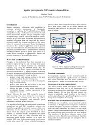
1. THE “OPSI” CONCEPT<br />
Single loudspeakers emanate the high frequency part <strong>of</strong> the<br />
WFS source, see Figure 1-1. The WFS array uses the lowpassed<br />
(f alias ) signals. These<br />
loudspeakers need to be spaced significantly wider than<br />
the loudspeakers <strong>of</strong> the WFS array <strong>and</strong> thus produce a<br />
<strong>stereo</strong>phonic image. The low <strong>and</strong> the high frequency<br />
source are expected to merge unless the difference in their<br />
incident angles is not too large. This technique is called<br />
“OPSI” = “Optimised Phantom Source Imaging <strong>of</strong> high<br />
frequency content wavefield synthesis”. Figure 1-2 illustrates<br />
the method <strong>of</strong> deriving an OPSI signal for the WFS<br />
array.<br />
Figure 1-1: Example <strong>of</strong> an OPSI system: Three loudspeakers<br />
replace the WFS array for reproducing the high frequency part<br />
The WFS virtual source <strong>and</strong> the phantom source are expected<br />
to merge <strong>and</strong> to be perceived as one auditory event.<br />
Their directions must not be too different, otherwise they<br />
would be separately perceived. This difference shall be<br />
called the OPSI localisation error. It should be smaller<br />
than a maximum allowed OPSI localisation error which<br />
was determined in a pilot experiment. A change in the perceived<br />
source direction does not exist in cases where the<br />
OPSI localisation error does not exceed 5°. The locatedness<br />
<strong>and</strong> the localisation focus <strong>of</strong> the OPSI source, however,<br />
was the subject <strong>of</strong> another experiment which is not<br />
described here [15]. The OPSI system turned out to be<br />
roughly similar to a conventional WFS system with the<br />
same WFS spacing regarding these attributes.<br />
Figure 1-2: Creation <strong>of</strong> OPSI signals: The WFS array is fed with<br />
the low-passed WFS signals only. The <strong>stereo</strong> loudspeakers are<br />
fed with the high-passed WFS signals after a level adjustment.<br />
The signals are split at the crossover frequency f cross .<br />
Simulations <strong>of</strong> the OPSI localisation error show that the<br />
error depends on the position <strong>of</strong> the virtual source. Also the<br />
size <strong>and</strong> position <strong>of</strong> the <strong>stereo</strong> loudspeaker setup influence<br />
the performance. In order to optimise for a minimum OPSI<br />
localisation error, the choice <strong>of</strong> the suitable <strong>stereo</strong> loudspeakers<br />
depends on the synthesised virtual source distance.<br />
In the case <strong>of</strong> plane waves or sources with larger<br />
distances, more than just a few <strong>stereo</strong> loudspeakers have to<br />
be used.<br />
2. EXPERIMENT: TIMBRAL<br />
FIDELITY<br />
2.1 EXPERIMENTAL SETUP<br />
The experiment aimed to compare the <strong>sound</strong> <strong>colour</strong> <strong>properties</strong><br />
<strong>of</strong> different WFS systems as well as OPSI <strong>and</strong> <strong>stereo</strong>.<br />
It was performed with a modified MUSHRA method<br />
after ITU-R BS.1534 which utilised fixed anchors exhibiting<br />
spectral alterations <strong>of</strong> different degrees. In pilot experiments<br />
a suitable anchor was found, being the reference<br />
signal, processed with sine-ripple spectra <strong>of</strong> different ripple<br />
depths (see [10]). The ripple depth (amplitude <strong>of</strong> the<br />
sine) is defined as the difference between the maximum <strong>of</strong><br />
the first half wave <strong>and</strong> zero. Five anchors were utilised; the<br />
ripple depth was 0, 1, 2, 3 <strong>and</strong> 4 dB. The utilised anchors<br />
are shown in Figure 2-1.<br />
It was decided to assess the system <strong>colour</strong>ation which was<br />
defined as an intra-system parameter. This means that in<br />
each trial only one system has to be assessed which makes<br />
the experiment design easier. In each trial 9 different signals<br />
were reproduced. These are:<br />
- the reference (direction -5°)<br />
- three stimuli in other directions than the reference (-<br />
10°, 3°, 15°). The directions were chosen such that the<br />
differences between reference <strong>and</strong> stimulus direction<br />
were unequal for all stimuli.