Proportional directional spool valve type PSLF, PSVF, and SLF ...
Proportional directional spool valve type PSLF, PSVF, and SLF ...
Proportional directional spool valve type PSLF, PSVF, and SLF ...

You also want an ePaper? Increase the reach of your titles
YUMPU automatically turns print PDFs into web optimized ePapers that Google loves.
D 7700 F page 14<br />
4. Characteristic data<br />
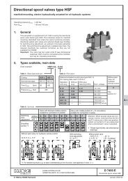
4.1 General <strong>and</strong> hydraulic<br />
Type coding<br />
Design<br />
Mounting<br />
Installation position<br />
Ports<br />
Port size<br />
Surface coating<br />
Mass (weight) approx. (kg)<br />
Temperature<br />
Rec. contamination class<br />
Operating pressure<br />
Control circuit<br />
Flow<br />
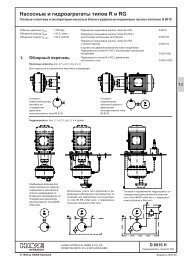
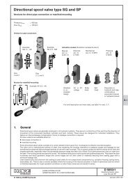
<strong>P<strong>SLF</strong></strong>, <strong>PSVF</strong> <strong>and</strong> <strong>SLF</strong><br />
Directional <strong>spool</strong> <strong>valve</strong> for manifold mounting, up to 12 <strong>spool</strong> <strong>valve</strong>s may be combined in a <strong>valve</strong><br />
bank by means of sub-plates, all-steel design<br />
Size 3 Size 5<br />
See dimensional drawings<br />
Indiv. section 4 x M8 4 x M10<br />
in sect. 5 ++<br />
Valve bank M8 M10<br />
Any<br />
P = Pressure inlet (pump)<br />
R = Return<br />
A ,B = Consumer ports<br />
U, W, X = Load-signal outlet at the indiv. <strong>spool</strong> <strong>valve</strong> section<br />
LS = Load-signal outlet e.g. connection of pump metering <strong>valve</strong> at <strong>PSVF</strong>.<br />
Attention: No pressure input!<br />
M = Pressure gauge connection (pump side)<br />
Z = Pilot pressure connection (20...40 bar inlet, 20 or 40 bar outlet)<br />
T = Control oil return port<br />
Y = Load-signal inlet port (end plate E 2 <strong>and</strong> E 5)<br />
P, R, A, B = Acc. to dimensional drawings (see sect. 5.10)<br />
M, LS, Z, T, Y = G 1/4 conform. ISO 228/1 (BSPP)<br />
U, W, X = Acc. to dimensional drawings (see sect. 5.9 <strong>and</strong> 5.10)<br />
Indiv. <strong>valve</strong> section <strong>and</strong> sub-plates: All surfaces corrosion-inhibiting, gas nitrided<br />
(Solenoid at actuation E... <strong>and</strong> additional functions F1...F 3, FP 1...FP 3, FPH 1...FPH 3 inc galvanized<br />
<strong>and</strong> olive-green anodized)<br />
Size 3 5<br />
Inlet section <strong>P<strong>SLF</strong></strong>, <strong>PSVF</strong>../.., <strong>PSVF</strong>..- 3.8 1 ) 3.3 1 )<br />
Valve section Actuation A, E, F, H, P 4.4 2 ) 6.6 2 )<br />
EA, PA 4.8 2 ) 7.0 2 )<br />
FA, HA 4.7 2 ) 6.6 2 )<br />
FEA, HEA 5.1 2 ) 7.1 2 )<br />
Blanking plate AX 0.9 ---<br />
Intermediate plate /Z AN..BN.. -- 3.1<br />
Sub-plates /3, /38, /4, /5, /53, /533, /534,<br />
/5 S, /3 X, /5 X, /6 2.2 4.3<br />
/3 AN... BN..., /3 A..B.. 2.5 ---<br />
/5 SAE, /5 SAE S, /5 SAE 8 -- 9.2<br />
/6 D SAE -- 17.0<br />
End plates E 1, E 2, E 4, E 5 0.8 1.8<br />
E 3 <strong>and</strong> E 6 2.1 3.1<br />
E 7, E 8, E 9, E 10 2.0 ---<br />
E 1 SAE ... E 5 SAE -- 2.9<br />
Adapter plate ZPL 53, ZPL 5 SAE 3 5.0<br />
1) + 0.6 kg<br />
at version with<br />
solenoid <strong>valve</strong><br />
WN1F(D), PA...PD<br />
acc. to table 8<br />
2) + 0.4 kg<br />
at version with<br />
functional cut-off<br />
(coding F.., FP.., FPH..<br />
acc. to table 16)<br />
Pressure fluid Hydraulic fluid (DIN 51524 table 1 to 3); ISO VG 10 to 68 (DIN 51519)<br />
Viscosity range: min. 4; max. 1500 mm 2 /sec; Optimal operation range: 10...500 mm 2 /sec<br />
Also suitable are biodegradable pressure fluids of the <strong>type</strong> HEPG (Polyalkylenglycol) <strong>and</strong> HEES<br />
(synth. Ester) at operation temperatures up to +70°C. HETG (e.g. rape seed oil) or water based fluids<br />
e.g. HFA or HFC must not be used!<br />
Ambient: approx. -40 ... +80°C; Fluid: -25 ... +80°C, pay attention to the viscosity range!<br />
Start temperature down to -40°C are allowable (Pay attention to the viscosity range during start!),<br />
as long as the operation temperature during consequent running is at least 20K (Kelvin) higher.<br />
Biodegradable pressure fluids: Pay attention to manufacturer's information. With regard to the compatibility<br />
with sealing materials do not exceed +70°C.<br />
Restriction for version with ex-proof solenoid:<br />
Ambient: -35 ... +40°C; Fluid: max. 70°C max. 70°C for version G 24 EX 70 Ambient: -35...+70°C,<br />
Fluid: max. 75°C<br />
ISO 4406 18/14<br />
p max = 400 bar; Ports P, P1, A, B, LS, M, Y<br />
The max. pressure achievable at the consumer side of the <strong>spool</strong> <strong>valve</strong>s is lowered by the amount<br />
equivalent to the internal control pressure drop at the 3-way flow regulator of the <strong>P<strong>SLF</strong></strong> (see curves)<br />
or at the pump flow regulator (<strong>PSVF</strong>)..<br />
Return port R(R1) ≤ 50 bar; port T pressure less with separate pipe (e.g. 6x1) to the tank. It is<br />
recommended to employ end plate E 1, E 2, E 3, etc. with an additional leakage port, in case higher<br />
return pressure is anticipated. Port Z approx. 20 or 40 bar (acc. to coding, see table 7) (outlet);<br />
≤ 40 bar (inlet)<br />
For control pressure, see Q-I-characteristics. The internal control oil circuit is sufficiently protected<br />
against malfunctions caused by contamination by means of a disk filter.<br />
Acc. to the specifications in table 14, in sect. 3.2.1