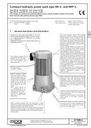
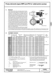
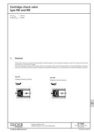
Proportional directional spool valve type PSLF, PSVF, and SLF ...
Proportional directional spool valve type PSLF, PSVF, and SLF ...
Proportional directional spool valve type PSLF, PSVF, and SLF ...

Create successful ePaper yourself
Turn your PDF publications into a flip-book with our unique Google optimized e-Paper software.
D 7700 F page 42<br />
c) Flow-pattern variations<br />
Flow pattern symbol J, B, R, O <strong>and</strong> I, Y, Z, V<br />
Oscillations may occur depending on application during start (e.g.<br />
winches) or during normal operation (e.g. crane booms). They can<br />
be caused by the natural frequency of the hydraulic motors or<br />
external load variations e.g. swinging load. The flow coding<br />
(table 15) of the respective <strong>spool</strong> should correspond to the cylinder<br />
ratio as far as possible.<br />
Symbols Description Application<br />
J, B, R, O Creation of a back<br />
pressure of approx. 20<br />
bar at 1/3 <strong>spool</strong> lift <strong>and</strong><br />
more.<br />
I, Y, Z, V<br />
Back pressure |p A(B)-R<br />
Creation of a back pressure<br />
of approx. 100 bar<br />
for up to 1/3 <strong>spool</strong> lift<br />
Symbols<br />
I, Y, Z, V<br />
Symbols<br />
J, B, R, O<br />
I Y Z V<br />
When combined with<br />
over-center <strong>valve</strong>s e.g.<br />
for boom controls<br />
Hydraulic motors (because<br />
of pressure rise<br />
due to area ratio 1:1),<br />
e.g. with cabin slewing<br />
Symbols<br />
L, M, F, H<br />
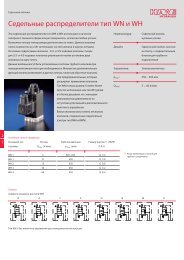
Flow pattern symbol W<br />
This 4/2-way <strong>directional</strong> <strong>spool</strong> <strong>valve</strong> is intended for applications<br />
where a constant velocity is required e.g. blower or generator<br />
drives. The ability of prop. speed control is restricted, but load<br />
independency is ensured via the inflow controller (table 13).<br />
Flow pattern symbol X<br />
This 2/2-way <strong>directional</strong> <strong>spool</strong> <strong>valve</strong> is intended for hydraulic<br />
motors (e.g. fan drives) <strong>and</strong> features maximum speed in idle<br />
position. The speed can be reduced proportionally down to<br />
dead-halt by energizing the side "b". The load-independence is<br />
provided when combined with an inflow controller (table 13).<br />
X<br />
Symbols<br />
W<br />
Available versions:<br />
SL 3-W 50/50<br />
SL 5-W 120/120<br />
Q max A, B (lpm)<br />
Coding acc.<br />
to table 13<br />
2<br />
(1)<br />
5<br />
SL 3-X 80<br />
Coding acc.<br />
to table 13<br />
2<br />
(1)<br />
5<br />
50 120<br />
(67) (150)<br />
67 150<br />
Q max A, B<br />
(lpm)<br />
80<br />
(107)<br />
107<br />
Flow pattern symbol P, A, T, Q, K (only size 3)<br />
These <strong>spool</strong>s show positive overlap. Type P overlaps in both switching<br />
directions, i.e. during elevation of the <strong>spool</strong> the connection<br />
P → A(B) is opened before of connection B(A) → R.<br />
This results in an undesired pressure intensification at cylinders<br />
(area ration . 1), therefore we recommend <strong>type</strong> A, T, Q or K as<br />
these have a one-sided overlapping only. They are intended for<br />
consumers such as hydro-motors / double acting cylinders (area<br />
ratio 1:1) with righting moments / -forces, as well as at cylinders<br />
with drawing loads (area ratio . 1). A short-term preloading<br />
prevents "lowering jolts" <strong>and</strong> "running empty". These <strong>valve</strong> <strong>spool</strong>s<br />
can substitute load-holding <strong>valve</strong>s to a limited extent. It should be<br />
taken into account, that a short-term working against the max.<br />
system pressure takes place.<br />
The flow coding for A should be selected higher than for B with<br />
<strong>spool</strong> codings A <strong>and</strong> T to prevent unintended pressure intensifications<br />
(for <strong>spool</strong> codings Q <strong>and</strong> K Q nom A < Q nom B )<br />
Symbols<br />
P<br />
A<br />
T<br />
Q<br />
K<br />
Available versions:<br />
SL 3 - I 6/6<br />
I 10/10<br />
I 16/16<br />
I 25/25<br />
I 30/30<br />
I 40/40<br />
I 63/63<br />
I 80/80<br />
SL 3 - Y 45/45<br />
Y 60/60<br />
SL 3 - Z 25/25<br />
Z 45/45<br />
Z 60/60<br />
SL 5 - I 25/25<br />
I 120/120<br />
I 140/140<br />
I 160/160<br />
SL 5 - Y 150/150<br />
SL 5 - Z 80/80<br />
Cylinder area ratio<br />
A piston /A rod<br />
= 1<br />
. 1<br />
Valve <strong>spool</strong> code letter<br />
Piston side<br />
connection A<br />
connection B<br />
P...<br />
A, T<br />
Q, K<br />
Example<br />
P 40/40<br />
T 25/16<br />
Q 40/63<br />
SL 3 - V 6/6<br />
V 10/10<br />
V 16/16<br />
V 25/25<br />
V 40/40<br />
V 63/63<br />
V 80/80<br />
SL 5 - V 25/25<br />
V 120/120<br />
V 140/140