Proportional directional spool valve type PSLF, PSVF, and SLF ...
Proportional directional spool valve type PSLF, PSVF, and SLF ...
Proportional directional spool valve type PSLF, PSVF, and SLF ...

You also want an ePaper? Increase the reach of your titles
YUMPU automatically turns print PDFs into web optimized ePapers that Google loves.
D 7700 F page 8<br />
3.2 Valve sections<br />
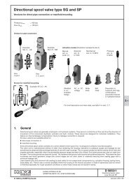
3.2.1 Directional <strong>spool</strong> <strong>valve</strong> (individual <strong>valve</strong>)<br />
Order examples: (<strong>valve</strong> bank) <strong>P<strong>SLF</strong></strong> A1 F/320/4 - 3 - A2 L 63/40 F1 /EA /3 AN320 BN320 - E1 - G 24<br />
(individual section) <strong>SLF</strong> 5 - A5 J 160/160 C250 /EA - G 24<br />
Note:<br />
Size specification is absolutely necessary!<br />
The <strong>valve</strong> <strong>spool</strong>s are subsequently interchangeable,<br />
e.g. if a different flow rating than initially<br />
planned becomes necessary (see sect. 6.3.4)<br />
Size<br />
Table 20<br />
Table 17<br />
Table 16<br />
Table 15<br />
Table 14<br />
Sect. 3.2.2<br />
Table 13:<br />
Coding<br />
A 2<br />
A 1<br />
A 5<br />
A 7<br />
A 26<br />
A 56<br />
A 8<br />
AR 2,<br />
AR 5,<br />
AR 7<br />
AX<br />
Spool <strong>valve</strong>, basic version<br />
Description<br />
St<strong>and</strong>ard, with inflow controller, for simultaneous load compensated moving of several consumers<br />
(3/3-, 4/3-way <strong>spool</strong> <strong>valve</strong>, st<strong>and</strong>ard <strong>type</strong>)<br />
Without inflow controller intended for singly / successively actuated functions. Additional functions on the consumer side<br />
are not possible. For the max. consumer flow of the individual consumer, see table 15 <strong>and</strong> sect. 6.1 b)<br />
With inflow controller (for symbol, see coding A2) but with reinforced spring at the 2-way flow controller (control pressure<br />
approx. 9 bar). Only usable in conjunction with connection block <strong>type</strong> <strong>P<strong>SLF</strong></strong> AH../...-3- or <strong>type</strong> <strong>PSVF</strong> with variable displacement<br />
pump / constant pressure system. Note see sect. 6.1 a <strong>and</strong> b.<br />
With inflow controller (like coding 2) but enforced 2-way controller spring (control pressure approx. 13 bar). Only available<br />
in combination with connection block <strong>type</strong> <strong>PSVF</strong> <strong>and</strong> variable displacement pump/constant pressure system, see<br />
note in sect. 6.1 b)<br />
Only size 3: With inflow controller coding 2 or 5, <strong>and</strong> additional rebound damping;<br />
Especially suited for oscillation inducing consumers (e.g. hydraulic motors with a low<br />
number of pistons)<br />
4/3-way <strong>directional</strong> <strong>spool</strong> <strong>valve</strong>, Makes only sense with flow pattern symbol L <strong>and</strong> H <strong>and</strong> maximum flow. Only usable in<br />
conjunction with connection block <strong>type</strong> <strong>P<strong>SLF</strong></strong>.H./... or <strong>type</strong> <strong>PSVF</strong> with variable displacement pump / constant pressure<br />
system.<br />
Like coding 2, 5, 7, but with additional check <strong>valve</strong> functionality (<strong>spool</strong> <strong>valve</strong> = slight<br />
leakage), see sect. 6.1 b<br />
Only usable in conjunction with connection block <strong>type</strong> <strong>P<strong>SLF</strong></strong>.H./... or <strong>type</strong> <strong>PSVF</strong> with<br />
variable displacement pump / constant pressure system.<br />
Blanking plate<br />
Table 14:<br />
Symbols<br />
L M F H J B R O G J, B, R, O, Valve <strong>spool</strong> with return throttling to assist<br />
I, Y, Z, V oscillation dampening, see sect. 6.1 c<br />
G<br />
W<br />
A, K, P, Q, T<br />
HW, OW<br />
X<br />
3/3-way <strong>spool</strong> <strong>valve</strong>, observe note in sect. 6.1 c<br />
4/2-way <strong>spool</strong> <strong>valve</strong>, observe note in sect. 6.1 c<br />
Valve <strong>spool</strong> with positive overlapping, see sect.<br />
6.1 c, only size 3<br />
Valve <strong>spool</strong> with wider fitting to prevent <strong>spool</strong><br />
sticking - intended for contamination prone<br />
systems<br />
2/2-way <strong>directional</strong> <strong>spool</strong> <strong>valve</strong> for hydraulic<br />
motors, see sect. 6.1 e, only size 3