Proportional directional spool valve type PSLF, PSVF, and SLF ...
Proportional directional spool valve type PSLF, PSVF, and SLF ...
Proportional directional spool valve type PSLF, PSVF, and SLF ...

Create successful ePaper yourself
Turn your PDF publications into a flip-book with our unique Google optimized e-Paper software.
D 7700 F page 4<br />
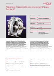
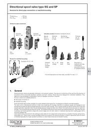
3. Available versions, main data<br />
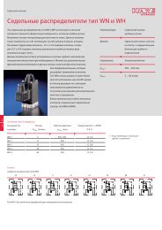
3.1 Inlet section (control section)<br />
There are two basic variations of connection blocks:<br />
' Connection blocks with integrated 3-way flow controller, suitable for a fixed pump system (open-center) -<strong>type</strong> <strong>P<strong>SLF</strong></strong> (see sect. 3.1.1)<br />
' Connection blocks suited for a variable displacement pump system (closed center), a constant pressure systems, or if a<br />
second or more separately located <strong>directional</strong> <strong>spool</strong> <strong>valve</strong> banks are fed in parallel - <strong>type</strong> <strong>PSVF</strong> (see sect. 3.1.2).<br />
Order coding for an inlet section as individual section (examples): <strong>P<strong>SLF</strong></strong> A1 F/250 - 3 - G 24<br />
(Attention: Size specification absolutely necessary - 3 or -5) <strong>PSVF</strong> A2/300 - 5<br />
3.1.1 Inlet sections for fixed pump systems (with integrated 3-way flow controller) <strong>type</strong> <strong>P<strong>SLF</strong></strong><br />
Order examples: <strong>P<strong>SLF</strong></strong> A 1F/300 /4 - 3 -...-E1 - G 24 (<strong>valve</strong> bank))<br />
<strong>P<strong>SLF</strong></strong> A H1F/300 - 3 - G 24 (individual section)<br />
Table 2<br />
Table 1<br />
Table 10<br />
Table 1: Basic <strong>type</strong> <strong>and</strong> size<br />
Coding <strong>and</strong><br />
size<br />
<strong>P<strong>SLF</strong></strong> A ..-3<br />
<strong>P<strong>SLF</strong></strong> A ..-5<br />
Description<br />
Individual<br />
section<br />
Max. pump delivery flow<br />
(lpm)<br />
approx. 100<br />
approx. 350<br />
Type <strong>P<strong>SLF</strong></strong>...-5 can be converted any time for use with<br />
variable displacement pumps (similar to <strong>type</strong> <strong>PSVF</strong><br />
AS..-5), see sect. 6.3.3.<br />
Table 3: Coding of the sub-plate for the inlet sections<br />
Coding<br />
/4<br />
/UNF 4<br />
/6<br />
/7 SAE<br />
Size<br />
3<br />
3<br />
5<br />
5<br />
Ports ISO 228/1 (BSPP)<br />
or SAE 514 J<br />
P <strong>and</strong> R LS, M, T <strong>and</strong> Z<br />
G 3/4 G 1/4<br />
1 1/16-12 UN-2B 7/16-20 UNF-2B<br />
G 1 1/4 G 1/4<br />
SAE 1 1/2” G 1/4<br />
(6000 psi)<br />
Table 2:<br />
Coding for additional elements for notes <strong>and</strong> descriptions,<br />
see sect. 6.1 a)<br />
Coding Description<br />
no coding St<strong>and</strong>ard Integrated combination of orifice, check<br />
<strong>valve</strong>, pre-load <strong>valve</strong> (pre-load pressure<br />
approx. 25 bar).<br />
W<br />
G<br />
H<br />
T<br />
Like st<strong>and</strong>ard, but with increased throttle effect<br />
Restrictor check <strong>valve</strong> (without sequence <strong>valve</strong>),<br />
increased throttling effect<br />
Coding for 3-way flow controller with increased circulation<br />
pressure (see sect. 4.2). Intended for <strong>valve</strong><br />
<strong>spool</strong>s with increased flow (coding 5 acc. to table 15),<br />
pre-selector <strong>spool</strong> <strong>valve</strong> (coding 8 table 13).<br />
Only available for <strong>type</strong> <strong>P<strong>SLF</strong></strong> A..-3<br />
Provision for locking the 3-way flow controller to<br />
enable use with variable pump systems.<br />
Note:<br />
Symbols<br />
Sub-plates with SAE-flange must not be combined<br />
with sub-plates featuring tapped ports<br />
(e.g. /5 S)<br />
Basic <strong>type</strong> <strong>and</strong> additional elements<br />
(see table 1 <strong>and</strong> 2)<br />
Sub-plates (see table 3)<br />
Additional elements<br />
These additional elements are<br />
illustrated in flow pattern<br />
symbols of size 3, they do<br />
apply to size 5 in the same way.<br />
<strong>P<strong>SLF</strong></strong> A../../4-3<br />
<strong>P<strong>SLF</strong></strong> A../../UNF 4-3<br />
<strong>P<strong>SLF</strong></strong> A../../6-5<br />
<strong>P<strong>SLF</strong></strong> A../../7 SAE-5<br />
<strong>P<strong>SLF</strong></strong> AG../..-3<br />
<strong>P<strong>SLF</strong></strong> AG../..-5<br />
<strong>P<strong>SLF</strong></strong> A(H)../..-3<br />
<strong>P<strong>SLF</strong></strong> A(H)W../..-3<br />
<strong>P<strong>SLF</strong></strong> A(H)../..-5<br />
<strong>P<strong>SLF</strong></strong> A(H)W../..-5